Analog output signal stops
Greetings,
I use a DAQ Assistant to output a 0 - 5V signal. I added a Triangle pattern at the entrance of the DAQ Assistant.
The point is that I do 0 - 5V and then back to 0V. But the problem is that the DAQ Assistant stops just to 1V.
P.s. I have the DAQ Assistant, in a loop For
Thanks in advance
Tags: NI Software
Similar Questions
-
Generating analog output signals 4 with different frequencies
Hi all
I was trying to say to generate 4 different signals at different frequencies
1. first waveform is a sine wave with 5000 Hz,
2. other with 8000Hz,
3. third, one is a square with 25 Hz waveform and
4. fourth one with triangular waveform 50 Hz
all waveforms must be generated simultanoeusly.
I tried to generate with the task unique analog output and sample clock (clock rate is 100000). Cross in scope that I see only 5000 and 8000 Hz we generated correctly and the rest two waveforms show the incorrect frequency.
I guess that's due to the frequency of high clock to sample for more low frequencies for ex 25 Hz and 50 Hz. If I reduce the clock rate to get the lower frequencies properly so I can't generate frequencies higher correctly. (there's a clsh between frequencies and the clock frequency)
Is it possible to use DAQ board master sample clock and its magnitude downward revision (everywhere where it is necessary for each waveform separately) to generate all the signals at different frequencies at the same time in a single task?
-
variable phase shift between two analog output signals
Hey! I would drive two different piezo elements with an sine - / square signals and have a phase shifted output signals. After some trail and error, I was able to get a second analog output on my card PCI-6221 (using LabView 8.2) also allowed me to have different amplitudes for both signals. However, I could not output signal having a frequency different and most importantly to my request to have one of the signals variably shifted phase.
Thanks for the very useful suggestion. I have attached the file .vi installation I've run so far.
Hello!
A way to generate waveforms is using the analog waveform Toolbox. I created an example VI that is attached and that shows you a way to use the base generating function VI. I saved for LabVIEW 8.2.
I hope this helps!
-
Develop the analog output signal
Let me start by saying that I am a new user of LabVIEW. My experience with LabVIEW is limited to a briefing in which we covered documents in the guide, «Introduction to LabVIEW and Computer-Based measurements» manual the customer Hands-on With regard to what I'm trying to accomplish:
I'm using LabVIEW 8.6, OR cDAQ-9172 and number of NI 9205 and NI 9264 module. I have a load cell that requires a constant supply of 10V to operate. I don't know how to generate this signal or the signal in mV, which is removed from the load to the cDAQ-9172 cell. I tried using DAQ-Express for entry and exit signals. Once I have created two assistants DAQ, I'm not sure what to do next. In addition, the load cell has four sons: green, white, red and black. Green = + GIS, red = + EXC, white = - GIS and black = - Exc. The Red wire is connected to ao0 and the black wire is connected to the COM of NI 9264. the Green wire is connected to ai18 and the white wire is connected to the NI 9205 module ai26.
Any help on this is greatly appreciated!
Yatsco
Hello Yatsco,
Fan of the crows is correct that you would be more successful using a NI 9219 instead of the combination of the PCI module, HAVE / AO. However, it might be possible to use the modules, you should use the load cell, that you try to use, but we need more information on the sensor to say with certainty. A link to form would be preferable.
Assuming that everything would work out with the sensor itself, I would do something like the following:
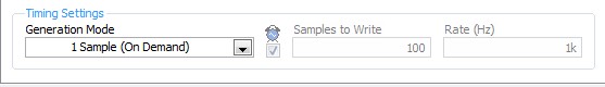
- Configure your analog output DAQ Assistant for output on the 9264 ao0, leave all default settings except for the generation Mode, you should change it to 1 sample (on request).
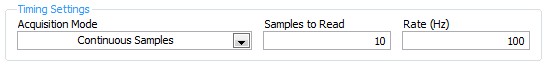
- Configure your analog input DAQ Assistant enter ai18, keep all the default settings again except for sync settings, which should resemble the following:
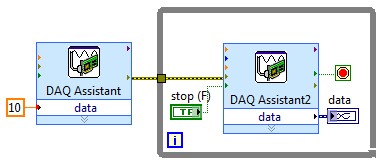
- Your drawing should look like this:
If you do this and you encounter problems with your sensor or its response after the datasheet (or at least the manufacturer and part number), and I'll look into it further.
- Configure your analog output DAQ Assistant for output on the 9264 ao0, leave all default settings except for the generation Mode, you should change it to 1 sample (on request).
-
Hello guys,.
I have a general question regarding the units of packaging such as the USB-9263 analog output signal. If I can use it instead of data acquisition to provide an analog voltage output?
Thank you
ELA
Yes, the 9263 can provide 4 output channels analog voltage (+/-10 v range) with up to 1mA of current drive. Looks like: it refers to the short circuit of conditioning of signals and some protection against overvoltage. Link below is the User Guide:
http://www.NI.com/PDF/manuals/372406b.PDF
-AK2DM
-
Several simultaneous analog output channels
I use DAQmx-NOR-USB.
I want to simultaneously generate two analog output signals, i.e. change the two outputs at the same time.
Simple example:
What is happening is that instead of two outputs simultaneous modification, there is 1mS delay:
I want to generate premium output, using two channels, but the delayed response is not acceptable.
Any suggestions?
Hi Seth B,.
Yes, it works!
A note: to make visible this property, I had to turn on "display all the attributes" in the menu "Select filter" (right click on the node property).
Thank you.
-
How do I get the analog input signal and send it to output analog (real time)
Hello world
I do a simple task in Visual C++ and I use PCI-6221(37 pin).
Basically, I want to send the same signal of "analog input" to the "analog output".
at the same time (or almost), to make real-time application.
Can someone provide me with sample program please.
I would be grateful if you could provide me with the great tutorial that explains
step by step everything about NOR-DAQmx for C/C++ programming.
Best regards
Khassan
This is my code in C++, you can optimize it if that seems too messy. This code reads the analog input signals and exports it through the analog outputs.
To make this code additional work of the directories include and library directories must be added to OR.
I hope it helps someone.
#include
#include
#include "NIDAQmx.h".
#include#define DAQmxErrChk (functionCall) {if (DAQmxFailed (error = (functionCall))) {goto error ;}}
int main (int argc, char * argv [])
{
Int32 error = 0;
TaskHandle taskHandleRead = 0, taskHandleWrite = 0;
Read Int32 = 0;
float64 context [1000];
char errBuffRead [2048] = {'\0'};
char errBuffWrite [2048] = {'\0'};
bool32 done = 0;
Int32 wrote;DAQmxErrChk (DAQmxCreateTask("",&taskHandleRead));
DAQmxErrChk (DAQmxCreateAIVoltageChan(taskHandleRead,"Dev1/ai0","",DAQmx_Val_Cfg_Default,-10.0,10.0,DAQmx_Val_Volts,NULL));
DAQmxErrChk (DAQmxCfgSampClkTiming(taskHandleRead,"",100.0,DAQmx_Val_Rising,DAQmx_Val_ContSamps,0));
DAQmxErrChk (DAQmxCreateTask("",&taskHandleWrite));
DAQmxErrChk (DAQmxCreateAOVoltageChan(taskHandleWrite,"Dev1/ao0","",-10.0,10.0,DAQmx_Val_Volts,NULL));
DAQmxErrChk (DAQmxCfgSampClkTiming(taskHandleWrite,"ai/SampleClock",100.0,DAQmx_Val_Rising,DAQmx_Val_ContSamps,1000));DAQmxErrChk (DAQmxStartTask (taskHandleRead));
DAQmxErrChk (DAQmxStartTask (taskHandleWrite));While (! fact &! _kbhit())
{
DAQmxErrChk (DAQmxReadAnalogF64(taskHandleRead,1,10,DAQmx_Val_GroupByScanNumber,dataRead,1000,&read,));
DAQmxErrChk (DAQmxWriteAnalogF64(taskHandleWrite,read,0,10.0,DAQmx_Val_GroupByChannel,dataRead,&written,));
}
_getch();Error:
If (DAQmxFailed (error)){
DAQmxGetExtendedErrorInfo (errBuffRead, 2048);
DAQmxGetExtendedErrorInfo (errBuffWrite, 2048);
}
If (taskHandleRead! = 0){
DAQmxStopTask (taskHandleRead);
DAQmxClearTask (taskHandleRead);
}
If (taskHandleWrite! = 0){
DAQmxStopTask (taskHandleWrite);
DAQmxClearTask (taskHandleWrite);
}
If {(DAQmxFailed (error))
printf ("error DAQmx: %s\n",errBuffRead); ")
printf ("error DAQmx: %s\n",errBuffWrite); ")
}
printf ("end of the program, press the Enter key to quit\n");
GetChar ();
return 0;
} -
Analog output of signal generation custom
Hello
I have a VI that generates a signal from the values in an excel worksheet. I'm trying this waveform through an acquisition of output data. I use a box NI USB-6211.
I copied the exit code for the acquisition of data from other VI that generates a sinusoidal signal coming from an excel worksheet. This program works very well. (attached for reference - Analog Output VI + sinusoidal waveform)
I have two problems at the moment. First of all, I get error-200560 about waiting until the function, attached.
Second output amounts only to about 5.5 v instead of 9V specified in the data.
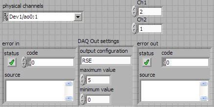
My VI generate several types of waveform according to selected tests, but I'm trying to get an output DAQ working with the first test, named "disconnection of the battery" work first before implementing it in the other tests so please ignore others for now. To run this battery select VI disconnect under tests select then direct to the attached excel (BD values under 10V) file.
I hope that I myself have pretty much explained, otherwise please ask for more! I'm new to LabVIEW so your help would be very appreciated.
Thank you very much
Parker
aeParker wrote:
I've made a few improvements to the VI but I always feel the DAQ 5 Cap output, 5V.
Dear Parker,
I guess that this statement is based on the values in the chart show, AO 0. However, this is not (necessarily) the voltage produced by AO 0, but rather the tension being sampled by AI0. If you look at the DAQmx create channel for the AI voltage channel, you will see that you have left entries Maximum and Minimum Value unwired, which means that they take their values default to + 5v and - 5v. This may explain the behavior of cutting that you observe. Try the + 10 and -10 wiring and see if that solves this problem.
Bob Schor
-
Analog output OR-6211 - tip of low voltage at the beginning/end of periodic signals
Hello
I use a data acquisition multifunction NOR-6211 at the exit of two analog voltage signals that are periodic. I read the values for the latter to a .txt file that is generated in Matlab. The two voltage signals are the same, however, one of them is 1/2 period out of phase from each other.
Here's my output information:
Frequency 100 Hz signal
Sampling rate of 200 k
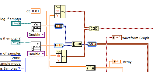
Number of samples 2 k
Text files have 2000 samples in them.
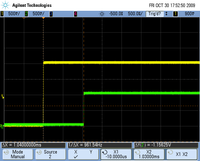
When I look at the output on the oscilloscope, the first signal looks great, but the second signal is a voltage surge at the beginning/end of the period. I checked the .txt files and the first starts at 0 and ends at just above zero. The second starts at approximately 288 mv and ends at just below 288 mv.
I have attached my .vi and a .jpg file showing the Spike. It stings to zero so I think it is a kind of buffer reset or something, but I can't understand this one... Any help would be much appreciated.
Thank you
Why are you converting complicated to and from DDT to get a picture of wave forms when you don't provide timetable information? Use Waveform build and build table as shown or just use the DAQmx Write DBL 2D value.
As Henrik, I fear that your data are not what you expect it to be. Put a graphical indicator or a table on the wires going to DAQmx writing to see what you have.
Lynn
-
To input analog shutdown when the analog output is completed and synchronization
Hello
I'm trying to get my LabVIEW program to send analog output to a computer and read acceleration using the cDAQ-9184. Chassis output that I use is the NI 9263 and the chassis of entry is the NI 9234. I generate a signal of white noise using LabVIEW Express signal generator.
The first problem I have is the synchronization. I had an old VI that has begun to measure the acceleration just about a second after the entry has been given to the machine. I used the LabVIEW tutorial on how to sync the analog input and output, only to discover that it does not work with two different hunts. Then I found another tutorial that shows how to synchronize different frames between them.
The second problem is the cessation of the LabVIEW program. What I want to do is to generate the signal and then simultaneously send and read the input and output analog, respectively. It is because I don't want a phase difference or any shorter signal for a direct comparison. But as soon as the signal is sent to the machine, I want the entry to stop analog playback and then then the LabVIEW program must stop. I want to be able to choose any length of signal to be generated and stop as soon as the entire duration of the signal has been sent to the machine.
I tried 'DAQmx stop', "DAQmx Timer" and 'DAQmx's task made?' and none of them have worked for me. It is also my first time on a forum posting, so I hope I gave enough information. I enclose my VI as well. The VI shows I read an entry for the analog input voltage, but I am only using this to try to get to the work programme.
I'd appreciate any help I could get.
Thanks in advance
Peter
Hi Peter,.
I have some recommendations for you that I think you will get closer to your solution. First of all, I assumed you meant that you had 1 chassis (cDAQ-9184) who had two modules in it (NOR-9263 and NOR-9234). My next steps are based on this assumption, so if it's wrong, please let me know.
For your first question about the synchronization, the code you provided is very close to what you need. You need to do, however, implement architecture master/slave for startup tasks DAQmx functions. To do this, you can add another frame to the flat sequence structure and put the master start task (input voltage) after the start slave (output voltage) task.
To manage your second question and that the program ends at the point where you, the first step is to get rid of all the logic that you use with the local variable of length of time. Rather than use this logic, just wire the node "task performed?" of "is task performed?" operate to stop the loop. This will cause your loop to stop as soon as the signal is sent to the machine.
I have some other recommendations for you that will increase the performance of your program:
(1) rather than writing on file inside the last loop, you can use the DAQmx Configure Logging (PDM) .vi. You will place this VI between DAQmx Timing.vi and DAQmx Start Task.vi to the task of the analog input voltage.
(2) after the last while loop, you want to stop the task and analog outputs as well with another DAQmx stop Task.vi.
(3) rather than using a local variable for the entrance of displacement and wiring it in the DAQmx Write.vi, you can wire directly from the output waveform of the wave to build function node.
That should help you get started in the synchronization of these tasks.
-Alex C.
Technical sales engineer
National Instruments
-
How to write constantly to analog output and read from analog inputs
Hi all -
I had a question about writing continuously to analog output reading simultaneously an analog input.
It's my first time to post a message to the community, so please let me know if I made mistakes.
I use Labview 2011 with a NEITHER-DAQ USB 6215.
I'm looking to generate a waveform and write it continuously in an analog output. It is then connected to an entry on the acquisition of data, where I am trying to sample the analog signal. (I realize, there is a system of trivial, but I'm hoping to build on it once I have run).
The task of reading from the analog input works fine, as I tested it in several other cases. I have a problem writing to the analog output.
For this task, I tried to follow the "Gen Cont Wfm Clck Int' VI to generate the wave form and start the task. I then try to write to the output of the analog timed loop. However, it does not seem to transmit a signal and doesn't give me any errors.
I have attached the VI but also a screenshot.
Please let me know if anyone has any ideas. I would really appreciate the help!
Thank you
Peter Borgstrom
We will review your tasks one at a time. First of all, the task of generation/Analog output Waveform. Generate you a waveform (I'm unsure of your VI if it is a fixed waveform or not) and send it to a defined output function to produce a waveform continuously, using N-channel and samples of N (where you set not these previously). You should not put this inside has timed loop, as the DAQ hardware has its own clock - if you simply put it in a while loop (with a stop to break out of the loop), the loop will call the function for the first points of N, wait until all N have been taken out, then call it again to another N points (up to what you press Stop).
Now, suppose that you have the output connected to a load voltage (say a decent resistance). You can wire the input terminals of your A/D converter through the same load and set up a similar analog input loop, running in parallel (i.e. in its own independent of the OD loop, while loop). You pourriez start together (with, say, a merged error since the initialization code line loops HAVE and AO become lines of error in "loops of sampling" described above), but you might want to delay loop (a little) the AI so that the OD has a chance to set the voltage before the bed.
I hope this helps.
BS
-
Analog output PCI-6251-DAQ-200016 memory overflow error
NI PCI - 6251 DAQmx, AIMD-752 motherboard, dual core processor, a lot of speed and the ram running WinXP Pro & LabWindows/CVI
get DAQ-200016 memory overflow error when I try to generate a signal of analog output with a rate higher than about 32 000 samples/second (?)
going on what? I have never seen it before. Is this a problem with the motherboard? "It's the same product on the CVI code example" \Cont Gen Volt Wfm - Int Clk\ContGen - IntClk.cws.
If someone has had this problem, and is there a solution?
Thank you
PS: full text of the message reads:
Measurements: On-board memory precision passing. Due to the limitations of system and/or the bandwidth of the bus, the driver could not write data to the device fast enough to track the rate of output of the device. Reduce your sampling rate, change the method of transfer of data (from interruptions on DMA), use a product with more on-board memory or reduce the number of programs that your computer runs simultaneously. Task name: _unnamedTask<1> Code of State:-200016
Well, I found my answer. For later use, Olivia NI Apps Engineering suggested I have change the mechanism of data transfer by this Knowledge Base document:
http://digital.NI.com/public.nsf/WebSearch/C326F7D33CA6DB0E86256DFE008043B7?OpenDocument
... so I inserted the line of code between the creation of the area of OCCUPANCY of the channels and set up the example of clock calendar.
DAQmxCreateAOVoltageChan( ...

DAQmxSetAODataXferMech(TaskHandle,chan,DAQmx_Val_Interrupts);

DAQmxCfgSampClkTiming(...
now, I am able to generate output to a 2.35 MS/sec... max sampling frequency not quite the 2.86MS / sec indicated in the specification 6251, but close enough that I'll stop complaining

-
Decent analog output of my Qosmio F20-154
I use my Qosmio as a Microsoft Media Center with my TV connected via VGA output. It gives me a pretty good image.
However, my TV does not support most of the modes of zoom for VGA; or it does for DVI or HDMI.
So I tried the image output via S-Video - which produces a shitty and unacceptable photo.
Unfortunately, Qosmio has no TV output, so I can't try it.
So, does anyone know of a piece of hardware that can be used to make the Qosmio to produce a decent analog output, such as TV-Out (antenna) or Composite?
Thanks in advance,
BrianAs far as I know you have only two options to send the video signal.
Qosmio F20 supports viga video and s-video ports.
So either you will use the video VGA (15-pin) port or output video super TV (S-Video) 4pol mini to connect the TV to the laptop...I have connected my laptop to the TV also using the s-video port and the photo quality is OK.
Please check you s-video cable and if possible test another in addition, I would recommend check some settings on the TV and s-video option
-
Simulate the analog output of arbitrary waveforms
Simulate it Arbitrary Waveform VI Express can be used to generate analog signals to the physical channels in analog output mode systems such as the NI 9263? I am trying to use the VI arbitrary signal generator to produce a signal used to excite the magnetic coils.
Why don't you just try and see what happens? As far as I know, it should work.
-
output signals of the rectangle a PEAK sine wave conversion
Hello
I have a question on the treatment of a PIC16F84 output signals. It seems that the simulation of Multisim does not work properly - but before I blame Multisim, I ask the community NOR or software engineers or a solution. Because I'm German, you are invited to continue this thread in German if it is allowed by the rules of the forum. If you need additional information to analyze my problem, I'll be happy to provide.
The circuit itself has to convert "composition by pulse" signals "tone" (DTMF tones). So you can get old, classic phones work on new devices that do not support the "composition of pulse" more.
The circuit is powered by the analog telephone line current loop line. The PIC is provided by a rudimentary voltage regulation and count pulse signals (voltage failures / power interruption on the telephone line). After that the captain means the series of impulses in their equal number (e.g. 3 pulses = number 3). The captain gives finally two signals with different frequencies to generate a DTMF tone (e.g. number 3 here is 697 and 1477Hz). As you can see in my PDF file attached, it works very well.
Now I have to convert the rectangle wave given by the captain to an at least similar to a sine wave form - otherwise the device that receives the DTMF tones won't understand them.
So I connected a low-pass filter at the output of the PIC. Now, expect the rectangle signal to be smooth in a way as the 'e-function' will (loading / discharging a capacitor through a resistor). But the results are very far from that - as you can see I have very strange curves.
When I implemented a frequency generator with the same output signal as the PEAK and the low pass filter even I get curves as expected.
So we can say that the output of the PIC works like a frequency generator in my circuit. But why does the filter not behave as it should?
I've tried a lot of different values for the parameters of my RC-filter and simulation - this does not solve the problem.
It would be nice if someone has any idea how to solve this problem.
Thank you.
The output impedance of the PEAK may be too high. May be that my car 50 output? Try scaling of impedance of the filter. Do the 10000 ohms resistance and capacitor 10 nF.
Lynn
Maybe you are looking for
-
I have a question for the SMU 4139. It is able to program the output resistance/impedance. Its output can be used to simulate a resistance? Floating? Or he is still stuck to the ground. THX.
-
Hello Sir Recently replaced the hard drive in my laptop, forcing me to re-install Windows 7 Ultimate edition. The laptop is a HP pavilion n011tu 15 Installation went well, now trying to download the drivers for the network card on another computer an
-
With microsoft Outlook express 6, I can't send emails
I clicked on HTTP messaging and the only was hotmail and I use it. But my problem is that I finished everything quickly, because the thing to fill the empty spaces. But when I sent the email, then I would say that it does not work. If the system has
-
AAA - ACS - users authenticate to different NDG
Hello... We have an ACS appliance integrated with MS AD and the users are authenticated successfully. Our requirement is that we have 3 departments with 20 switches each. I created 3 (NDG) network device groups for each Department in ACS with 20 swit
-
computer is going to connect on the screen and less thsn 2 minuets when idell
With the help of Windows 8 64-bit on Lenovo idea C440 I tried update my PC and get all the files. But I still get the log on screen that requires a password. Please help me some one Thjanks