Host DMA to the synchronization of the target
I use two hosts to target DMAs to generate two arbitrary waveforms to be taken out of the anAO module. I want these waveforms at the exit at the same time, but it seems as if the waveform leads the other by several micorseconds. The two waveforms are in two separate tables, passed to the DMA. It seems as if the shift is on the side of the host. I tried using the timing with the vi sync loop and the offset setting timed loops, but that seems to increase the interim more, or no effect. Is there a way to get these DMAs to start to pass the data at the same time?
Peter
What you can do is pack the two waveforms in a DMA and analysis, and then to the AO.
AO generally uses I16s to represent the waveform data and the bus DMA U32.
Use the number of join to combine both forms of wave, then DMA composite signal, then use AO divide numbers.
I used this successfully with good results.
Tags: NI Software
Similar Questions
-
I'm trying to transfer a picture of the LabVIEW host program to the target in real time on a cRIO.
I'll set up a controlled loop that transfer values one via shared Variables.
It works fine when I run running to highlight.
However, if I have both allow to run at full speed, something goes wrong
and the size of the array ends correctly on the target.
Is there some tricks on how to transfer tables down
host to the target, or all the other pitfalls I should be aware when
work on a real-time target?
And Yes, I never took the course of the RT, so there might be some vital info miss me.
Martin
Hi Martin,
Why don't you use a SharedVariable taking a picture? Why can you transfer data one by one?
-
Number of items in the target to host DMA FIFO
Hello world
I would like to transfer a set of datapoints of an FPGA to a RT-host controller using a fifo DMA. If I use the 'Get number of items to write' function on the FPGA target, can I get the total number of items in the two buffers, or just one on the FPGA target?
(see http://zone.ni.com/reference/en-XX/help/371599H-01/lvfpgaconcepts/fpga_dma_how_it_works/)
markus_a wrote:
If I use the 'Get number of items to write' function on the FPGA target, can I get the total number of items in the two buffers, or just one on the FPGA target?
The FPGA will have no idea how big the DMA is on the side of the host. He can't see his own DMA buffer.
Get the number of items to write just tells you how many items are not used by the DMA (ie the number of items that currently write to the DMA without waiting for items to be offered by the host reading).
-
How can I transfer more 64-bit data to the target host?
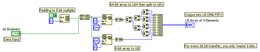
Hi all, I currently use fpga PCIe-7851r card to drive my camera. There were 64 lines to remotely control. So what I did generates the commands on the host pc and transfer it to the target via DMA FIFO. The data type of the FIFO is U64, i.e. each digit control 64 DIO lines. But the issue becomes complex when I transfer 66 command-line. I tried to create 2 FIFOs, but I can hardly do the 2 Sync FIFO.
I think I might be able to create 2 tables U64, one contains the original 64 line, s command and the other for the 2 line (a loss) information. And then I have them interleave in hospitality and decimate them in the target. There should be enough cycles to it. But I don't think it's a good solution. Is there a better method? Thank you.
LabVIEW 2009, Windows XP, PCIe-7851R
Kind regards
Bo
Using the techniques highlighted in this tutorial:
http://zone.NI.com/DevZone/CDA/tut/p/ID/4534
You can use code like this:
-
Hi all:
I was working normally with my NI9024 CRIO to my work. I went home and when I came back the other day. I tried to compile my application to work.
The surprise was that I got a strange message "access denied: the IP address of this computer host is not on the list of eligible access of the target." Now, I can not connect a CRIO device. I tried to reset all the IP addresses in the CRIO and my PC computer. What can I do?.
Yes. This is the solution. I had to uninstall the NOR-RIO software on the target. I have uninstall everything on the CRIO. Then I reinstall the software, but I had also to program the fpga, the host and target. And I also have my IP, on the measure and automatition software. I found a big bug I guess.
Thanks anyway. National Instrument of love. Hope to work there one day.
-
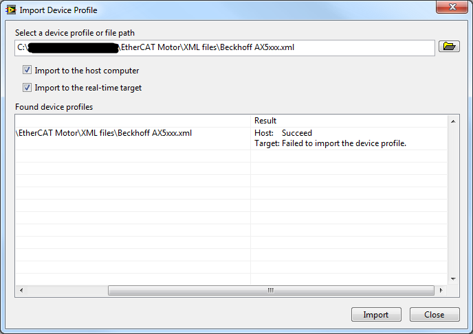
Part 3 EtherCAT Slave: importing XML Device Profile succeeds on host but fails on the target
Hello
I'm trying to control a 3rd party via EtherCAT servo drive:
- Master: NOR-cRIO 9024
- Slave: Beckhoff AX5203
I downloaded the files of unit on official website of Beckhoff Description: http://www.beckhoff.com.au/english.asp?download/elconfg.htm (Beckhoff_EtherCAT_XML.zip)
I followed the instructions to http://digital.ni.com/public.nsf/allkb/FDA1318A8909D02C862574510060DB62 to import the profile description of the device.
Curiously, the import was successful for the host (and I can now access this device in the LabVIEW LVPROJ file), but it failed for the target.
Why could this be? (There are no diagnostic messages)
Hi JKSH,
Looks like you are using NOR-Industrial Communications for EtherCAT 2.7 or later. What is you project connected to the target when you try to import the file? How are you connected to the target? What is your firewall block FTP transfers? Do you need the ability to programmatically discover slaves EtherCAT (such as DSM or using the VI of Modules Refresh)? If you just want to program the EtherCAT Slave in the LabVIEW project, import the device description files to the host is all that is needed.
Best regards
-
SIT error 14104, dll runs on the host, but not on the target
Hello
I have problems of deployment dll (compiled in 2007 with Microsoft Visual C++ .NET 2003) Simulink in LabVIEW (2009 SP1). My target system is a desktop PC with LabVIEW Real-time 9.0 installed.
I created a simple Simulink model which mulitplies an entry with a Gain and returns the result. I compiled using the nidll.tlc as a target file system.
Then, I created a LabVIEW RT application that uses this DLL. I created exactly the same application as the host VI and VI target. On the host VI everything works fine. On the target VI, I get error SIT 14104.
What I did to solve this problem? I followed the steps on http://digital.ni.com/public.nsf/allkb/C7FF960E0A6C219A8625729600104615 . I have manually deployed the dll on the target computer. I used the suggested compiler. There is a lot of memory on the computer (RAM and HDD) target. And I'm not using a CRio system.
Does anyone have an idea how to fix this error? I will attach the sample project labview and the MDL and DLL to this post. Don't forget to adapt the DLL-path if you test the program.
Kind regards
Thomas
Well I found a solution.
I had to deploy the DLL manually on the target, but not in
ftp://IP_Address/ni-rt/system/as the link above is said but rather inftp://IP_Address/.Problem solved.
Kind regards
Thomas
-
I moved a listener on a host in a House different oracle. The headset works fine, but EM 12 c shows that the listener is down with the following summary:The listener is down: even if a listener with the name "AUDITOR", is running on this host at the port: "1521", it has not started using "the target LISTENER. ORA file. CORRECTIVE ACTION: To monitor this "EM listener target" with its current configuration, you must stop the process of listening running and start it using the Listener parameter file: opt/oracle/product/12.1.0.2/network/admin/listener.ora. Alternatively, you can update "this target LISTENER. Location ORA setting"with the location of the listener running, which started using the: opt/oracle/product/11.2.0.3/network/admin/listener.ora.
EM 11 g, I simply changed the configuration of the listener for the different oracle home, argued the change and in a few minutes the listener would show that 'UP' with the oracle of new home. I upgraded to MS 12 c (12.1.0.4) and can't find how to do this. Can someone give me the procedure.
Thank you
Ron
Hi Ron,
Can you please do the following?
-Create a for the listener listener.ora file, stop and start the receiver using the listener.ora file. If the file is located in a default location, set the TNS_ADMIN environment variable to that location before you start the listener.
-Log on to the EM console, go to the homepage of the listener.
-In the Oracle Listener menu, select target Configuration > Configuration of the analysis.
-Ensure that the parameters, including the Listener.ora directory, are properly.
Kind regards
-Loc
-
After that host on vSHere 4.0 strightly connected to iSCSI (initiator) host cannot ping the server iSCSI (target), but target can. And iSCSI works well. I mean I can create and use the iSCSI disk, why? It makes me confused.
Thank you!
Geoarge,
iSCSI traffic uses a VMkernel port, instead of using the command 'ping', use 'vmkping '.
André
-
Target to host DMA FIFO not compensation when they are arrested
I use a PXI-7841R (Virtex5) and 32-bit data to the host via DMA FIFO transfer. When you read the FIFO on the host for the first time, the data are "stale" (which means that it is not what is currently coming in the FPGA, but what came in a few seconds ago stale). I tried both a stop and a configuration for clear memory FIFO before I use them. Documentation on one or both of these so-called clears the target and host the FIFOs. Does not help in both cases. With readings of the second and the following, FIFO has then 'valid' (same data as it appears on the FPGA entry node). What is curious is that each reading exactly the same thing:
- Stop the FIFO (must erase all data)
- Elements of reading 375 of the FIFO. (repeated playback of the FIFO)
Also interesting: FPGA FIFO is implemented for 255 elements. The first 255 items host-side contain the data "stale" on the first reading. It reminds me of the never erased FPGA FIFO.
Answered by support OR. The documentation for the FIFO, stop and configure FIFO is in error. Cars of documentation will be written against them.
Solution:
These methods remove only the FIFO on the side host. Data FPGA FIFO must be read following until no element.
-
How to debug the program Labview that runs in the target of the RT of a Compact RIO
I use CRIO-9073 for the acquisition of data from sensors. Program Labview is written in RT target and target FPGA. It is posssible to make step wise execution for the program written in the target RT and FPGA target the way purpose us for the debugging of the program in general OS.
MJM,
The only way to use the debugging on a VI wrote to FPGA tools is to simulate running on the host computer. You can then deploy the compiled FPGA code on the target and run your VI RT in debug mode if you use the communication of the façade with the host PC.
-
Cannot run Simulink DLLs at the same time that the execution of the target time real VI
Hello
What I try to do is run a dll created in the Simulink model to control some servo through a CompactRio 9014.
For the moment, I managed to create three screws
(1) in the FPGA target that performs the PWM channel desired
(2) which takes the value of a variable that contains the desired position and network that feeds to the 1st VI
(3) a VI that is running on the host computer that changes the value of the network variable to change the position
I can get these three work screw and the servo controlled, but when I try to update the value of the network variable using simulation, by deploying to the target of RT simulation and running, he said:
' Access denied: this objective is already used by another host or project. »
I guess that's because the project is already connected the cRio, so I unplug and am able to deploy the model files.
However, when I try to run one of the screws in the Targer RT as well as simulation I get the error:
"This VI is downloaded to the target, but is not present in the project you are trying to deploy. All the screws on the target will be closed unless you choose to add the missing project VI. »
With a large number of missing screws...
I'd do this wrong, i.e. is there a simpler way to control inputs FPGA using the simulation, or is there something I have missed?
Thank you
Geoff
Hi Geoff,
I think I understand what you're trying to do and what you've done so far.
If I'm not mistaken you have passed through the SIT connection manager, set your target RT (select DLL, mappings and hardware i/o) and this is his 'magic '. If this is the case of look for the project pilot LabVIEW which was created by the SIT connection manager. This should live in the same folder where is your DLL. Open the pilot project, search for VI driver and open it. Then go into the Sub - VI # 5 has with the name of the loop rate Base. It's the Subvi who reads/writes on the material and the reads/writes the data to the DLL/OUT model. If you want to read the output of your model and then manipulate the data that is where you need to add your code.
Inside of this Base rate loop VI there is a Subvi with number 4 and called SIT take model Timestep. This VI is the one who makes the call to the DLL model. The output of this VI is your data from the model. This data goes into slot - VI # 5, which is responsible for the drafting of these data to the material. Since you want to manipulate that data from the model, you need to recover data from the wire coming from the Subvi 4 (SIT take model Timestep) before it gets to the Subvi # 5.
In this VI of Base rate loop, you will see that there are a few empty block structures. These images are for you to put any code you want. The reason is that any changes you make to the driver VI and subVIs that aren't inside of these frame structure will be lost if you decide to go in the connection manager to sit DOWN again and make some changes. The VI pilot gets new script whenever you do something in the SIT connection manager. Whatever it is inside these frames will not be erased.
So, if you have a code you want to run in parallel to the simulation you just have to drop it inside this driver VI. Very probably within this Subvi 5 (Base rate loop). To add your code just drop the VI in one of these settings and make any changes that him so that he can read the data in the model. Furthermore, the model (Subvi 5) data in a table. For the index of each element in the array and its meaning look for a file in the same folder where the DLL is named
readme.txt ports. This file has a description of the inports and small ports and their indexes. This VI driver is called when run you the host VI so you won't have to run sepearately.
Kind regards
Ricardo
National Instruments
Systems engineering
-
Options of DMA with the NI PXI for the PCI 3 rd-party with no DMA controller device
Hello
I need to extract data my device PCI 3 rd-party at 22 MB/s. The fastest, that I was able to continue to use NI-VISA 5.4 in LabVIEW 2013 is 1.6 MB/s with the function move in 64. There is no DMA controller on the 3rd party device. I was hoping to use the DMA of the host controller and a VISA MEMACC object, but I fell on 3229I2RA knowledge base: How do NI PXI controllers support DMA (Direct Memory Access)? The KB has that "our PXI controllers support only the PCI specification and therefore do not a DMA controller on the motherboard." If there is no DMA controller on the PCI 3 rd-party device, is there no DMA option for my 3rd - party on NI PXI controllers device?
Thanks for your time and your thoughts,
Steve K
Currently, there is no controller PCI DMA accessible by the user on computers NI PXI.
-
Access denied error connecting to the target RT
Hello
I use LV2009 on a desktop host and RT 9 on a target PXI. I can connect to the target through the project with the original target embedded sw Explorer but cannot access the modules of IO MAX due to a driver version (DAQmx) inconsistancy between the host and the target. When I install the DAQmx 9.3 drivers on the two systems that I can connect and access as the target I/O via MAX modules but cannot connect to the target through the Project Explorer. I gives me an IP address in the host not to mistake of authorized access list, even if I've added to the list of users under properties of the target. Something in the DAQmx update is complete my ability to connect through the Project Explorer.
Any help would be appreciated,
Thank you
Dave
Hi DDockery,
Our objectives of RT keep record of system information in a file named nor - rt.ini
We do not suggest edit our files nor - rt.ini if you are not similar with them.
Important lines in the ni - rt.ini follow the lines:
Server.TCP.Access = "' + * '"
RTTarget.IPAccess = "' + * '"'+' * means that each IP address can access
If you have any more specific questions or unconfortable editing the .ini file please contact Supportm technique of NOR, create a Service request and an Applications engineer can help out you.
-
FPGA target host DMA FIFO multi-channel
Hi people,
I have a little trouble to collect my FPGA application data. The control of my FPGA application loop is running and read data from set point between a host and target FIFO to a period of 50 uSec. I run a separate loop to write data collected form two channels in a target of FIFO host over a period of 1000 uSec. I'm taking the data from both channels and its reading on the host in bundles of 500 data samples. The first problem I have is that my method of reading times unless I put my data acquisition loop to run at a much slower pace. My FIFO depth host side is 60000, almost as large as the total number of data samples that I expect to collect in total.
I have another problem when trying to write the data to a table. Even if my method of reading does not expire, I don't think that will record the first beam of data that are read. I've initialized an empty table outside my acquistion of the side loop host and used the table VI build to take the current data set and add it at the end of this table. I then store in a shift register and pass it in the next iteration where I try to join the new data set to the old and so on. I expected to get a table with all the data, but as I said I'm only collecting the first set of 500. I wonder if my program structure is correct. Any help anyone could offer would be greatly appreciated. I have attached a few pictures of my reference request. Thank you.
Hi Daniel,.
Thank you for your response. I think I found a solution to the problems that I had. Looks like it was a combination of a couple things. First, the data acquisition loop was running not until the movement was already over since I plugged the condition to stop the loop of writing deposit directly on the data read loop. This problem has been fixed by creating a shared variable for the stop condition and it wiring to two loops independently. This explains why I got only the first set of data, as it was stored in the FIFO until the end of the movement. However, the FIFO of feedback was still time. Before attaching the stop condition error, I placed a probe on the "items remaining" wire of the read method and concluded that there was only 1023 elements (the depth of the FIFO on the side FPGA) even if I set the FIFO depth host side to 60000. "» I realized it was originally due to the Read method not called for the first time until the end of the movement. Although the problem of break for most fixed condition this problem given that the Read method was now called during the movement, I decided to take a preventive measure and calling the 'Start' before the movement FIFO method is started just to make sure that the memory of PEP on the side host is available immediately.
So yes, it turns badly I put sync settings have been well after all. Good call on the reversal of the order on the Array function to build. Oh, and I also had to move the waveform diagram to until the table is built so that it is not Replot the old data on top of all the new data it receives. On the same note, I moved to the indicator in table at the end outside of the loop of reading. Thanks again for your help.
Kind regards
John has
Maybe you are looking for
-
prefixes and units of first hp
According to the manual, if you want to use a prefix with units, you select the prefix first. When I do this (after you put a value on the line of writing, of course), the prefix is indicated in brackets in the input line and the units menu disappear
-
Question I have another type of problem with Firefox Description Window "Ready to Install" Firefox "Software Update" appeared. The folder "C:\Program Files\Mozilla Firefox\updates\0" contained the files update.mar, update.status and update.version. E
-
Need driver for SD card on my satellite
Hello My SD card was working and now it isn't I am running Windows XP Home edition on my machine and would like to know what it works. Thank you
-
Cluster (buttons and the radio channel controls) - select the right file
I have a list of text files and I need to select and open an of based on radio button selection. How to sync the radio button with control of the chain so that I can get the name of the control of the chain and open the right file name? The attached
-
How can you identify entries available sound card?
The "Sound Input Configure.vi" requires a device identification number that seems arbitrary. The express VI for sound cards, 'Acquire Sound', pulls a description of each available on the PC input device somehow. Is it possible to programmatically d