Redeclenchables pulse using GPCTR0 on 6062E STC
I have the desire to have an external synchronization signal (too short a duration) detected by a jury of 6062E and output a pulse of longer duration as a timing signal that I would read on an analog channel as well as other sensors on other analog channels. I used the example program 2055.zip, STCgeneratesinglepulse, for LW/CVI as a starting point. I modified the sample program so that it is redeclenchables instead of just pulse. This code example uses GPCTR0. The program works but not as I expected. GPCTR0_OUT has the pulse output generated and programmable duration that I want. GPCTR0_GATE is the input trigger/sync signal. What I've found, is that the DOOR has a constant voltage of + 5V signal. The problem is that the only trigger that works is an intermittent grounding to the GPCTR0_GATE. I was keen to work with external synchronization signal (short signal down-up-down). I was using the DAQ card + PIN 5V power to mimic an external trigger. How can I use such a trigger signal to generate the impulse? I have included a stripped to the low, short version of the revised program sample below and also as an attachment.
#include "nidaqex.h".
/*********************************************************************
* Sample program: based on 2055.zip
* STCgenerateSingleTriggeredPulse.c //changed to redeclenchables
*
* Description:
* Generates a redeclenchables digital pulse 1ms LOW and 100 ms HIGH aid
* General counter 0 after tripping (for devices with the)
* Acquisition of data-STC counters/timers)
*
* Pins of connection information:
* Your digital output pulse will be on the GPCTR0_OUT pin (2 for 6062).
* Connect this output to an analog channel for time synchronization w / normal DAQ.
* Connect your trigger pulse for digital on PFI9/GPCTR0_GATE spindle (3 of 6062).
* Plug the Locator on the ground at the 'digital ground' PIN (4 / 18 of 6062).
*
* To trigger, connected to pin 3 on the ground. But this isn't what I want.
* Want relaxation to be a HIGH LEVEL of BASS. How?
*
* The presence or absence of next line had no effect.
* Secret = GPCTR_Change_Parameter (iDevice, ulGpctrNum, ND_GATE_POLARITY, ND_NEGATIVE);
*
*********************************************************************
* Used a second computer/data acquisition monitoring system.
Monitoring system connected to the DAQ computer
* ---------------------------------------------- -----------------------
* ACH0 (68) GPCTR0_OUT (2)
* Rider to DGND AIGND (67) (4) ACH8 (34)
*
* OR
*
* Use the counter on the second computer/data acquisition monitoring system.
Monitoring system connected to the DAQ computer
* -------------------------------- -----------------------
* GPCTR0_OUT PFI9/GPCTR0_GATE (3) (2)
* GND GND
*
*********************************************************************/
void main (void)
{
char c; for the test
I16 Secret = 0;
I16 iRetVal = 0;
I16 iDevice = 1;
ulGpctrNum u32 = ND_COUNTER_0;
u32 ulLOWcount = 100; 1ms
u32 ulHIGHcount = 10000; 100ms
u32 ulLOWcount = 2; 0.02ms
u32 ulHIGHcount = 10; varied 0.1ms for testing
Secret = GPCTR_Control (iDevice, ulGpctrNum, ND_RESET);
Secret = GPCTR_Set_Application (iDevice, ulGpctrNum, ND_RETRIG_PULSE_GNR);
Secret = GPCTR_Change_Parameter (iDevice, ulGpctrNum, ND_SOURCE, ND_INTERNAL_100_KHZ);
Secret = GPCTR_Change_Parameter (iDevice, ulGpctrNum, ND_GATE_POLARITY, ND_NEGATIVE);
Secret = GPCTR_Change_Parameter (iDevice, ulGpctrNum, ND_GATE, ND_PFI_9); Gate, apply trigger here
Secret = GPCTR_Change_Parameter (iDevice, ulGpctrNum, ND_COUNT_1, ulLOWcount);
Secret = GPCTR_Change_Parameter (iDevice, ulGpctrNum, ND_COUNT_2, ulHIGHcount);
/ * To print a counter pulse, you must call Select_Signal. */
Secret = Select_Signal (iDevice, ND_GPCTR0_OUTPUT, ND_GPCTR0_OUTPUT, ND_LOW_TO_HIGH);
Secret = GPCTR_Control (iDevice, ulGpctrNum, ND_PROGRAM);
printf ("apply your trigger pulse to PFI9 now. \nThe rising edge is armed and the second falling edge is in the value. \n") ;
c = GetChar (); This simulates normal DAQ.
Secret = GPCTR_Control (iDevice, ulGpctrNum, ND_RESET);
/ * Note that the following call to Select_Signal causes the
output high impedance that will probably bring the logic
HIGH level, if there is a pull-up on this PIN resistance. (Check your)
Manual of equipment.) If you do not want this behavior, comment
the next line. */
Secret = Select_Signal (iDevice, ND_GPCTR0_OUTPUT, ND_NONE, ND_DONT_CARE);
return;
}
S_Hong,
I solved my problem.
I had in my code
iStatus is GPCTR_Change_Parameter (iDevice, ulGpctrNum, ND_GATE, ND_PFI_9);.
and was my trigger for entry. This is false because PFI_9 is an echo out of everything my trigger is connected to.
I changed the statement to
iStatus is GPCTR_Change_Parameter (iDevice, ulGpctrNum, ND_GATE, ND_PFI_0);. for the source of the signal.
and now a trigger on the PIN PFI_0 generates the impulse.
Tags: NI Software
Similar Questions
-
Calendar synchronized with Diuble pulse using PCI-6601
Hello
I'm trying to run a PIV of Labview 8.5.1 system using a PCI-6601 map at the exit of the signals for the laser and the camera.
This requires a line for the camera, one for the FPS (first removal of pulse) and one for the Q-switch.
The difficulty is in the need of a double pulse on the Q-switch for mode double frame PIV.
The distribution box that I use is not one NOR one and I don't have access to 3 outputs four against, otherwise, quite simply, I would use a BNC t with two pulses slightly staggered junction.
I have access to a BNC-2110 timing box, but I think it is not compatible with the PCI-6601 and have no funds to buy a BNC-2121 right now.
I managed to create a double pulse by using one of the counters with a finite number of impulses set to 2 and then stop the task, then run this in a timed loop.
However, it is then based on the software, which is not precise enough for the application, and I can't figure out how to get the timed loop to run from the time of 20 MHz of 6601 map base.
I could be missing something obvious here, or perhaps is more annoying? I'm fairly new to DAQmx.
Thanks in advance
Joe
Dominic makes a good point about the operating system, but really the best solution is to use the hardware timing when possible.
I have set up an example that shows how you can implement different sets of impulses finished using the calendar of the Commission. It requires the use of two meters, but then again a generation of impulses finished the fact (on the 6601).
Communities: Generate several Cycles pulse finished using two countersAlternatively, if you have another signal that you want to use to trigger each set of pulses (rather than to specify a rate so that they occur as in the example above), counters on a 6601 are redeclenchables then you can use the external signal to trigger the generation over time and time again without having to stop the task in the software.
Best regards
John
-
How to set the output meter channel to generate a signal pulse using DAQ6008
Hello there I am generating a pulse signal of 100 Hz and a duty of 20% of the 6008 data acquisition cycle using visual studio 2013. I have code that needs to generate this but I'm not sure on how to set the channel output meter. When I run this NI MMAX and my vb error code indicates that the physical channel is not supported. I am a user of data acquisition were first and would appreciate any help offered.
If you look at the USB-6008/6009 User Guide and specifications, you will see that the counter in these devices cannot rely as edges of entry. It cannot generate a pulse.
Lynn
-
Generation of pulses using NOR-PXI-5421 FGen
Hello Sir/Madam,
Question:
We use the Funktiongenerator NOR-PXI-5421 and just want to generate a pulse, because it can be done in almost all cheap Funktiongenerator.
Unfortunately, I can't find a way to tell the Funktiongenerator to generate a pulse. I can generate Singals as I like, but don't know how to generate a single pulse.
Perhaps you have a program that gives me this opportunity.
Thank you for your support.
Hi Jens,
You can try to use the Council 5421 scripts. The following examples of LabVIEW: "Fgen Arb Script.vi" or 'Fgen switch between Waveforms.vi' use of script to generate signals, you can create a script that generates a single DC pulse of high level in the same way.
I hope this information helps you.
Best regards
Blase
-
Generation of pulses using PCI-1428 to CC1
My laboratory uses an external signal generator to generate a pulse to trigger a line scan camera and continuous acquisition of image acquisition card. The lab has just acquired a new camera and unfortunately I can not use the external trigger on the camera connection. I understand that PCI-1428 cannot external signal to a line of camera control. I tried to generate a pulse of MAX, but he won't let me have a pulse with less than 24 US pulse width.
So first, I was wondering if there is a way to generate a pulse with less than 24 US of MAX pulse width.
And if this is not possible, is there a way to generate a pulse of Labview similar to he'S generation.vi of pulse but he sent via the CC lines for the order? Also, how can I program it to make the generated pulse is sent as soon as the frame grabber receives / detects the start of the external signal?
Thanks for your help.

Don't know who did the file of the camera, but the 1428 can generate pulses with a period of 40ns on CC1 (a time base internal 50 MHz is used at the moment of high/low pulse). You can use NI Camera File Generator to modify existing camera files:
http://sine.NI.com/NIPs/CDs/view/p/lang/en/NID/14207
It has good documentation for how to configure the settings of the pulse. If you still have problems, you can view the camera file, let me know what you're trying to use the mode, and which calendar you want pulse and I was able to address the issue, but I recommend trying OR Camera File Generator first... make a backup of your file to camera to keep your original autour.
Hope that helps,
Brad
-
How to connect to the list of the pins for a redeclenchables pulse train
Hello
I'm relatively new toDAQmx, especially for the counters. I have problems to determine what pins to plug on the DAQ card. I would like to run the vi described here, but am not sure how to connect the card. I looked at the manual of the X series for the pinout descriptions, but I don't know how they apply to the program on this page. When I connect DOOR a meter, THE, A, B pins, etc.?
Any input on what to connect or pages that may make how to connect the counters would be very useful.
Thank you.
Your most recent post of links to an example more advanced sounding & I recommend that stick you with something simple to start.
Your first post links to such an an example where the signal of pulse train going out of Ctr0_Out. Ctr1 is used to make the trigger and the 'break' (enable / disable) Ctr0. However, much of this stuff is configured using some features of DAQmx such that you don't need to physically connect the pins between the two counters.
Only physical wiring that you need is to plug your physical digital trigger to the PFI1 signal and connect Ctr0_Out to some external thing must receive them. As long as your device is called "Dev1", I think this example to work.
I know there are some docs useful for more general info on the pins meter & behavior, but I don't remember quite so that I have not watched for them for many years. Meanwhile, here is a * little * bit General description I wrote myself once.
-Kevin P
-
HP/Agilent 33120 A pulse, use burst mode
Hello
I'm trying to trigger a pulse of demand on from a HP 33120 A function generator.
The pulse must be a 0 - 5V simple, with frequency/period adjustable ramp. I was able to get as much of the FG by use of burst mode and trigger manually on the front panel. Now, I would like to get the same functionality from a LabVIEW VI.
Although there is a driver for the device, the burst feature is, unfortunately, not applicable to the model that I use. I found a similar problem on the forums and follow the code of the SCPI provided in the answer with some of my own humidification (http://forums.ni.com/t5/LabVIEW/33120A-Pulse-Mode/td-p/1088106).
Unfortunately, my VI does not produce the same waveform as the manual release out of the front panel. It hovers at the offset value and gives me a few square wave to zero when I run the VI. Square waves are spaced oddly and I usually see 4-5, even though I specified 1 cycle in VI. The 33120A reading, I feel that this is of my do not turn off the previous signal but, if this is the case, I can't understand how I would do.
I start to move away from using only the drivers by changing the code of the SCPI, but I'm still pretty new to this. Would appreciate some advice on what could be the problem. I modified my original VI twice; Once configure only the FG burst wave parameters manually and one just put up the waveform with no shine. The first don't not gave me much better results and the works of the latter very well so I'm back to the question of thinking are in transition.
I enclose the original VI (b) with the two modifications to the case where (c and d).
Hope to hear from you,
Yusif Nurizade
Edit: Burst chain should say TRIG: SOUR BUS instead of EXT, although neither works.
Or you have the appropriate firmware in you function generator?
Have you checked this with Agilent? -
The cheapest way to produce a TTL pulse using a chassis SMU-1062 q
I have recently updated an installation of a PXI-6534 surfboard in a to a Council SMU-6537 PXI chassis in a chassis SMU-1062 q.
One of the things that I forgot I needed is a way to output a TTL for some devices that I control of LabVIEW even software that I use... I counsel 6052E in my PXI chassis, that I used with CA-1000 enclosure for this TTL, but I always use this card in my PXI chassis, so this isn't an option.
What is the easiest way to get a TTL pulse out of my system SMU (cheaper?)? I can't use the SMU-6537 jury as it is used for other tasks (fast) (I mean the connector is directly linked to a device to communicate with).
Thank you
X.
Howdy X!
The cheapest way I can think of to generate a TTL pulse would be to use the USB-6501. Note that it only supports only avoiding so the length of the pulse is not exact, but if this fits within the limits for you request it's the cheap solution. Otherwise, I would recommend a card PXI DAQ as the PXI-6220.
Concerning
-
How to count the pulses using RIO (FPGA)
Hello
I want to use RIO (FPGA) for counting the pulses produced by a sensor,
but I don't know how to program. can someone help me.
Thanks in advance
CAIX wrote:
Hello
I want to use RIO (FPGA) for counting the pulses produced by a sensor,
but I don't know how to program. can someone help me.
Thanks in advance
Search for example for 'Meter of RIO' finder. There are dozens of examples that should help you.
-
How to generate a single pulse using PXI-4461 in Labview
I need to generate a single positive pulse is 100ms using an OD on the PXI-4461 with DAQmx Labview
I have trouble getting the exact time of the pulse.
Help, please.
Thank you.
He works, see attached pattern obtained.
Thanks to NI Applications Engineer ally Finney for example.
-
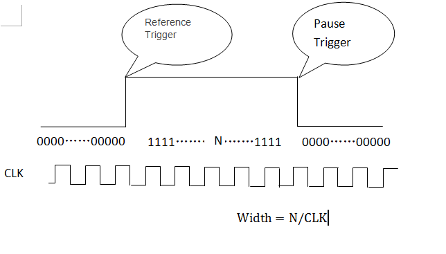
How to measure width of digital pulse using SMU-6548
Measure the digital signal of high level pulse width (a few seconds)
1US accuracy requirements
Thank you
Hello
You can configure the trigger of the reference and the break, and you will get a table as below. Calculate the number of 1,
The pulse width is N/clock. -
Encoder pulses using PCI4E reading us DIGITAL
Hi all
I'm new to this forum so I hope I post the question in the correct Council.
I have an encoder connected to the Board of PCI4e.
The problem is that when you try to measure the speed, I get different results using different methods:
So I want to measure the frequency of encoder impulses.
I'm trying to understand what function PCI4E gives me this information
If anyone knows please tell me.
Thank you
Gil,
Thank you very much!
-
Photon counting using Photon unique cash Module and PCI-6602
Hi all
I am currently working on program couting of photons using a single (Excelitas) and PCI-6602 photon counting module connected to the BNC-2121.
I took a glance at other positions, but I still couldn't solve my problem (or, again, I'm not sure if yes or no, the problem is the specification of the material).
In the program, I'm generates a trigger to 1 MHz pulse using a trigger in a separate loop.
Other than that, I have loops of the producer-consumer model to get data and do a simple subtraction to calculate the number of photons in 1 microsecond.
According to the values connected to 'Input.BufSize' of buffer DAQmx and "Samples per channel" DAQmx calendar, I could change the loop number that the program has done its job correctly.
With the values, the program acquires photon 1 MHz with signls for 139 times.
After that, the program stops and the loopback number increases very quickly.
When I forcifully took stop the program, while the loop number increases very quickly, the program appears "error-200141".»
The error that says "data has been replaced before it can be read by the system." Mechanism of data transfer is interrupted, try to use DMA or USB in bulk. Otherwise, divide the input signal before taking the action. "even if the meter explicitly works in DMA mode by using the sample clock.
I wonder there is nothing that can solve my problem or even the only solution will buy a better Board of counters/timers.
Thank you all for reading this.
I will be very happy with any index
Kind regards
Myeongsu
Yes, the same thing happens on my system.
It does not happen with PCIe-6612.
I found more strange things:
When I start to reduce the frequency at a time given (800kHz) can fill the buffer, it will not start since the beginning of the buffer. He can go to the beginning of the buffer only at 100 kHz for my PC.
Options to fix:
(1) PCIe-6612. Seems to work. I tried streaming at 10 MHz, 5 min - fine.
(2) reduce the frequency of the pulse. If your laser supports 100 kHz, you're fine.
(3) put in place additional synchronous counter at 100 kHz. Basically, it's material average number of photons by 10 pulses.
(4) read 2 adjacent pulses each 1/50 kHz - then your data transfer will be 100 kHz and you will get the number of photons of this impulse of the 20 - th.
Programming issues:
(1) remove the display of the received picture, make only the processing of data and show results if you really need it.
(2) clock.vi sample sets the buffer size, if you specify the size of the buffer, do this after this vi.
(3) I deleted unnecessary "loop generation." He is running on the hardware and stops when you stop it - after reading the loop ends.
-
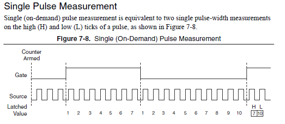
single pulse width measurement
Hello
I'm trying to measure the duration of a single pulse using ctr0 on an SMU-6361.
The signal in the attachment Capture7.jpg, goes PFI 9, ctr0 door.
The problem is that the counter see ' s the front up and stops. The pulse width is not given as can be seen in the output (Capture8.jpg).
I get the same results by using Meas_Pulse_Width.vi example.
Is something wrong with my SMU-6361?
Oh, I think I know what it is.
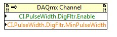
Change the task "pulse width" (a single pulse of height) instead of "Pulse" (the high and low time of a pulse repetition measures). Change the DAQmx Read to use Ctr > single sample > DBL (instead of pulse). Change the property filter node digital to use the corresponding properties of the "pulse width" (the filter is still necessary):
The task of the pulse was not period initially because you receive a series of noise pulse repetition (and so it was a very low period). With the filter, this time since the noise disappears now and the single pulse did not finish measuring the pulse (which requires a high and some time):
For the record, I agree that it is confusing that there is the "pulse" and "Pulse" measure and they do different things.
Best regards
-
I use LabVIEW2010 for the width of pulse measurements (duration of the pulse). using DAQ PCI-6052E. This is my program!
But my no good result! Help me!
My sensor is the SRF05 ultrasonic sensor
my result is not good, because I received the result but if large (very large) can be over 400 s
I don't know why?
Maybe you are looking for
-
my hp does not illuminate
-
My laptop Dell Inspiron 1525... When typing, the cursor jumps around & inserts as I type
When you use the keyboard, the cursor will jump to another place in what I typed & insert here where it shouldn't.
-
Software: Microsoft Word 2003, SP3 Hardware: Dell desktop Operating system: Win7 64 bit "of origin". Printer: all-in-one hp 4620 Note: 'print page' and other wireless diagnostic ePrint tool work very well. Problem: Unsable of printing from Microsoft
-
In Outlook 2003, I keep getting a popup asking the user ID and password.
In Outlook 2003, I keep getting a popup asking the user ID and password. This continues after I provide the information requested. How can I stop this?
-
AVCHD videos will play in Windows XP SP3? How
My video file output camera Sony's AVCHD. I have a hard time downloading it on my Windows XP SP3. AVCHD is playable in XP? My video software is Corel Videostudio Pro X 4 and the manufacturer says that works with Windows XP. I can't download my video