Error-1073807297 PXI-4071
Hello people,
I recently updated my CalExec 3.4 3.4.1. Desktop XP OS.
I can't calibrate the PXI-4071, I have not had any problems in the past.
MAX has no problem seein' and it makes even the inside however calibration option, with CalExec I get as much as
update from the slot, after that this error... Error-1073807297.
I have attached a hood perforated of all error... can you help out me.
I have a Chassis1042 w / counterpart 8330 PXI AND PCI and PXI-GPIB.
Thanks in advance.
Hey JSOTO,
You connect to any equipment calibration using VISA? If so, you can check that all these devices are rising and successfully through VISA? If one of the VISA alias is incorrect, then could you appears as this error.
My recommendation is to start Trace of e/s OR (formerly known as "NOR-SPY) (start" all programs"National Instruments" NI Trace of IO). Then try to calibrate the unit. I/o path will record all calls VISA and could lead us to the root cause. Once you have saved the data, you can export it and send it to us. If you are not comfortable posting all data on this forum, then you can post only the steps leading to the error or we can contact you by e-mail and continue troubleshooting it.
Tell us what you find.
Tags: NI Products
Similar Questions
-
Error-1074118625 with the PXI-4071 and PXI-2527
When you use the LabVIEW and PXI-4071 PXI-2527 IVI drivers, I get a 1074118625 error in TestStand. The sequence that initializes the MUX, init DMM, connects the MUX, expected debounce, and then to the DMM reading, I get this error.
Error: niDMM .viExplanation of waveform (waveform data) reading is not found for the requested status code.
Check that the required status code is correct.
[Error code: error code defined by the user of 1074118625.]
This sequence of events is used successfully several times elsewhere in the TestStand. This error does not appear in any section of the knowledge base, or any help. Any explanation would be greatly appreciated.
I found this with google that seems like it could apply:
http://digital.NI.com/public.nsf/allkb/A593DEBFD86A69C68625727900748EEC
-
Problem of reliability data acquisition PXI-4071
Hello
I'm having a problem of reliability using my 4071 Pxi digitizer mode.
I have a number of tests that use the SMU-6363 (usually configured for DC) analog output to provide a stimulus for our own device, which has a number of a/d converters. We use the PXI system for calibration and testing.
1. I select a voltage ranging from tensions.
2. program the PXI-6363 to drive this tension
3 TIME about 10ms to settle. Note there no discrete capacitors or resistors in the circuit. Everything is parasitic and would generally be under the nF mark and less than 10 ohms
3. configure and Initiate() acquisition of data with the PXI-4071. In general, I use a sample rate of 1000 s/s and get about 30 samples (worth 30 ms). Activation is immediate and I used the default a queue time, 0, set the time and it doesn't seem to make a difference.
4. measure the voltage with the CDA. For debugging purposes I have sometimes made twice once before calling Initiate() and once after. The after is normal. The time required to measure the ADC is shorter than the acquisition time, but regardless of stimulation by the SMU-6363 is constant
5. extract the waveform.
6. the average waveform and compare the value of ADC measured by applying tolerances etc.
Here's the problem: it works well most of the time. But only 0.1% of the time (1 on an acquisition of 1000), I get 8-12 samples that are close to 0. It sounds like a problem of time settling (on the surface), but no matter the amount of wait time data, I always get this behavior. Not only that, but the tension before the call to Initiate() in height CDA, it always confirms that the motor voltage is already set to the programmed value. Nevertheless the acquisition presents near data 0.
So far our independent ADC always reports the expected before and during acquisition (100%) voltage. It's like the DMM input is disconnected during the acquisition during a period of time, because we have confirmed that the voltage is already present prior to the acquisition (component can). I have no errors the insider or FetchWaveForm calls. I still have all my samples. And 99.9% of the time that everything works as expected.
The DMM and ADC are connected to the same point and both are referenced to ground, and as I said before only the parasitic capacitance and resistance (cable). We use a matrix of switching (PXI-2530 (b) to make these connections. We almost always use 51/2 digits and 10V range for data acquisition.
Hello
I thought about it and was going to repost but am distracted.
The device with the ADC also has a mux and switches the mux to an internal node. It only switches when measuring and is open at other times. There is a race condition where the acquisition starts too early and maintains the acquisition after that the switch is open. Unfortunately I don't have the option to trigger.
I forgot the internal mux that I had designed the test years ago and I did some updates to improve the stability of the test. That's why we start the ADC measurement when acquiring.
I just added a routine to reject samples below a threshold
-
The specifications for the PXI-4071 DMM indicate the input resistance can be chosen as 10 MOhm, 10 GOhm of the 100 mV 1 V and 10 V ranges. I see where it can be entered on the soft dashboard, but I could not find how to set up the input resistance when you use the DMM in a VI. Suggestions?
Thank you!
The f
You must use a property node.

-
I tried to change the name of the PXI-4071 "DMM" that worked, but when I try to launch the "self-test" or open the app it Panel always fails. This is also true if I pass the new name of the ivi driver. Return to the name "PXI-4071" makes everything works again. Note I managed to change the name of our PXI-2530 b 'SWITCH' and the name of our SMU-6363 to "MIO" and I could pass these names to their IVI drivers and they would work.
I messed with alias VISA, IVI logical names, but nothing works unless it is called "PXI-4071.
-
Hello
We use the DMM and SMU-6363 map to test a hardware device. We will also use a PXI-2530 b switching matrix. We will use the digital multimeter to perform the measurements of voltage, DC and AC, measurements of impedance (2-wire and 4-wire), frequency and waveform acquisition. Can the PXI-4071 left be 4 wire connected (black jacks taken connected and red connected) mode and still be used to perform all other measures (including 2 impedance of the cable). This would simplify the switch connections.
Current measures use the son + and LO, but the HI and S-can remain connected. The problem you are having is if you have an active device the digital multimeter and take you a 4-wire resistance and the measurement of voltage with all 4 wires connected and then change to a current... When you do this, short-circuit you the terminals of the DUT, on that you just take the measurement of the resistance. If the terminal HAD, say, a power supply 10V, then you have just shorted out. Of course, this isn't a problem if your Instrument is a passive device, or if you change just the unused two lead whenever there is an active device of low impedance.
If you want to make voltage, current and 4-wire resistance, you need all 4 wires. If you want to do the voltage and current, you will need 3 wires, but you could connect the s + Hi and then just do the two wires. I vote running every 4 son to your DUT for maximum flexibility.
2-wire resistance is a must if you are measuring resistance above 10 MOhm. Alternatively, you can use 4-wire for all measures.
-
PXI-4071 sampling too slow when using a hardware trigger
We use 3 PXI - 4071 s in parallel to measure with accuracy of high voltages. The program is written using LabVIEW 8.5.1.
An additional test condition has been added which requires the use of a quadrature decoder and the synchronous DMM.
We thought it would be simple, using backplane trigger 0.
However, something odd happens.
With a low-cut VI that uses a single DMM, we get 100 microseconds time to sample running with internal triggers. However, if the overall relaxation or trigger of the sample is set to TTL0, the sample time becomes so 5.1 milliseconds. It seems very strange that even just definition of overall relaxation, expected to affect only the time of the first sample, not the time between samples, has that effect. The plug for the DMM also said, that the maximum trigger rate is of 6 kHz.
We have confirmed this reported sample time is independent of the speed of the clock actually connected to TTL0. If the clock is faster, it gets the reported sample time. If it's slower, the samples occur on the edges of the clock.
Does anyone know if there is a parameter that has a default that changes based on the source of command and can be changed to work around this problem, you?
I found the solution to this.
Over time the value-1, the DMM uses a short value (less than 100 US) to set hour when, in modes triggered internally. However, he used much longer (about 5 ms) when the value - 1 and with the help of a hardware trigger.
If the running-in is set to 1e-5, i.e. 10 microseconds, "the estimate" returned for conversion period goes from 5.1 ms 100, we and conversions actually occur at a rate set when clocked with trig 0-5 kHz
-
How to acquire data through several channels in parallel using E 6070 PXI, PXI-4071 and LabVIEW?
Hello
I use LabVIEW and NI PXI-4071 PXI NOR 6070E to measure the current through a variable resistance. Now, I use a single channel of SCB - 68, but I want to add another channel at the same time so that I can have two resistors instead of one that I cam measure current through them.
I have attached a Pdf file showing installation of equipment to use and code LabVIEW also.
Can someone look at these files and give me some guidelines or ideas that can help me solve this problem, please.
Thanks in advance.
Best regards
Shaheen.
Your 4071 can do a measure at a time. Your data acquisition cannot measure resistance is not she of the analog inputs.
However, you could use a multiplexer and multiplexer your 4071 DMM. This habit give you simultaneous action, but can acquire data one after the other, the speed depends on the multiplexer, you choose!
I hope this helps.
-
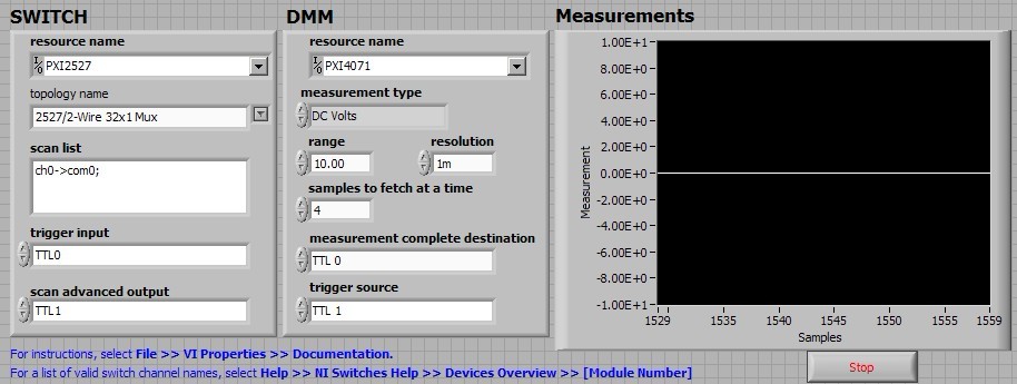
his strong 'Willy': niSwitch DMM PXI switch Handshaking.vi 4071/PXI-2527
I run the example of the handshake: "niSwitch DMM Handshaking.vi switch" for 2527 PXI DMM PXI-4071/SWITCH in a chassis PXI-1033 for a measure of 1 Volt DC test.
When I type 'Run', the switch block makes loud continuous noise "zizi"; the graph of 'measures' simply gives a 0 volt line. It's clearly wrong results.
My setting of this VI is as follows:
Anyone know what is the problem here?
Thank you
Bing
BLNG,
This noise is actually the sound of the relay control. Given that these relays are electromechanical relays, when the relay is closed, the two contacts essentially slap against each other and produce this noise. The buzzing you hear continuous, is because the relays are opening and closing several times. If you use the appliance in OR switch Soft Front Panel for example, you can hear a click by relay which is operated and closing individually each relay.
-
4071 PXI get negative resistance readings
Hi all
We are working on a system where we measure current leakage and resistance using a PXI-4071 with some other gear as well as a map to relay SMU and 2530 b..
The main problem is that for some measures of resistance we are seeing negative values as k - 200 or - 300 k. The digital multimeter has been in the range of 10 M. My understanding is that in this mode, the applied voltage is 10V and the test current is 1uA.
For me to see a negative resistance on some paths, the voltage must be opposed the 10V and superior to 10V. Is it a specific way of thinking? SMU is switched off and disconnected from the circuit when the resistance is measured.
It is not all EHRS that show this negative tension. The EHR is all passive devices (connectors) and so they do not have any large capacitances that could store a tension that I see. I take 5 readings with auto zero done when initially 5 readings.
What causes these negative readings? The connectors are immersed in a saline solution and there should be an open between the points to measure circuit, but when they start to fail a resistance can be seen.
Any thoughts would be much appreciated. Please let me know if you want more details.
see you soon
Peter
Peter,
To answer your questions, Yes, if the digital multimeter reads - 200 k there is opposing tension on the DMM. If you use 10 M Ohms then the opposing voltage serait.2 V and if you use the 1 M Ohms then the opposing voltage 2V. Also the negative reading is also caused by the flow of the current is in the wrong direction, because if there is a negative voltage then the current flows the opposite direction.
You can check the voltage at the terminals of the resistance while taking the measurement of the resistance using an other DMM, as a handheld DMM computer. It is more than accurate enough to check the voltage at the terminals of the resistance.
I hope this helps,
Brian P.
-
Variation of thermal EMF of the PXI-2530 modules
This message/question is a companion of my the most recent message in another thread.
In addition to watching some resistance higher than expected that affected current measurements using modules PXI-2530 multiplexer 4W topology, I saw systematic variation in track-to-track blood pressure measurements. Tensions would increase gradually through the 16 channels in a configuration by measuring the voltage at the terminals a resistor 1.5 kOhm with 0.5 au crossing (75 uV). I've identified that the thermal EMF of the reed in the PXI2530 module switches is on the same order of magnitude of these measures and set out to quantify the differences EMF thermal track-to-track between my three modules.
Test method: I have a TB-50 which is configured to mux the signals of tension for a DMM. I connected each of the four DB-50 one cable of 176 pins to this block and collected with a PXI-4071 pressure readings set to 7.5 digits precision in the range of 100 mV and > 10 GOhm impedance. For most channels, it took several minutes for the voltage stabilize - or at least appear that it was to stabilize.
I enclose three graphs. Note that the vertical scale is the same on each.
Data that triggered this survey was collected with MUX1, via connector P2 to voltage. The magnitude was not quite the same-probably related to the phenomenon of stabilization time, but obviously the worst group of channels three multiplexer modules.
The three modules were all bought at the same time (about 2 years ago), but had only limited its use in the first year or more. The three now have various 'mileage' based on my use. But MUX1 clearly behaves differently two other modules. The
I changed my test conditions to spend 0.5 au via a higher resistance to thermal EMF less important. The PXI-2530 sheets indicate that thermal EMF must be less than 50 uV. In most of my measurements, it is. But not for MUX1!
Any thoughts?
Thank you
Jeff
Hi Jeff,
You can check that all the three modules are PXI-2530, not PXI-2530 b (while, as the PXI-2530 b parts slightly higher thermal emf)?
Specification of emf thermal 50uV of the PXI-2530 is a typical value, is not a guarantee of spec. See a few channels higher than the spec is not a cause for alarm, but it shows that we must take account of this in our measurement error. Note that the industry standard for the technical measure thermal emf is to close the relay, wait a few minutes and then take a measure of tension. For example, if you scan through a switch faster than a relay per minute or so, the thermal emf will be less predictable and stable. A single module performs worse at these low voltages is not indicative that this module is a failure, etc. the module is fine. Unfortunately, the reed relays have more emf thermal relay of the armature, mainly because of the many layers of metal in a Reed compared to a frame (each metal junction is a source of emf if these metals are not the same).
Thermal EMF is proportional to the temperature, it may be interesting to note the position of the chassis of the less powerful module. Placing hottest modules (scanners, Ara, RF, etc.) will reduce the thermal emf.
-
Handshaking DMM with multiple switching devices - DAQmx error
Hello.
I am trying to create a loop of the handshake with DMM (PXI-4071), SWITCH (PXI-2569) and MUX (PXI-2575). The three instruments are in segment 2 chassis PXI-1045 (locations, 8, 9 and 10) and I use the ways of PXI trigger in the triggers of the route.
I followed the article NOR 'Multimodule Scanning with National Instruments switches' - I modified the example NI SWITCH "niSwitchDMMSwitchHandshaking" to set up another SWITCH, but when I tried to run the example, I got an error:
0xbffa6b9a - no lines recorded could be found between the device in the road. (screenshot pop up is in the attachment). It is the function of niSwitch_InitiateScan to the second switch that returned an error.PIX trigger change has no effect.
I tried the CVI and LabVIEW examples with the same result.
I even tried to use two 2575 MUXes - same result.Can someone tell me what I am doing wrong?
Hi Pavel,
I checked that the component that controls the routing of the TTL for the PXI is included in NOR-DMM 3.0.2 (latest version as of 06/14/2010). NOR-DMM 3.0.1 contains an older version of the TTL routing code and will therefore place several comprehensive lines scanning advanced on the same trigger.
Unfortunately, the component which controls TTL routing is one of the constituent elements of the software installed OR lower, and thus we do not expose it to the user. For that to work, we would need to uninstall almost all the software components of NOR, which is a major undertaking. Here's what I recommend instead:
For now, we will Garland triggers one switch to another. This will allow us to start development in OR-Switch; as soon as OR distributes a program, you simply change the triggers as they all point to the same TTL line. This will allow switches to operate in parallel rather than in series, and the passage of the switch of your project can run faster.
If we have to absolutely exploit the switches at the same time, I would recommend either uninstall all software of OR or get a machine with a fresh install of XP and then install not newer than 8.9.5, OR DMM 3.0.1 DAQmx software and NI - Switch3.8.
As I mentioned earlier, NEITHER is aware of breaking backward compatibility and we are committed to reintroduce the old features in a future release of the pilot.
Keep this thread bookmark and post back in a month or two and I'll let you know if we have any updates.
Have a great day!
-
Dear Sir.
Nice to meet you.
When I run the SMU-4141 "Adjust voltage Leve.vi niDCPower Cal" calibration function niDCpower version 1.8.
It shows an error "function of calibration is not supported by the device." (false cae)
But if I run the calibration function SMU-4141 "niDCPower Cal Adjust voltage Measurement.vi", (real deal)
It will work.
See attachments.
My equipment list:
Windows XP SP3
LabVIEW 2011
niDMM 3.0.5
niDCpower 1.8
PXI-1073 case with 2 cards.
SLOT2: SMU-4141
slot6: PXI-4071
Could someone tell me the solution?
Hi Peter,.
The calibration process indicates that the call of the function of voltage adjust NI - DCPower Cal calibrates both the output level of the device as well as the ability to measure of the device. It is even for the Cal of NOR-DCPower function adjust a current measurement.
You must perform a calibration automatic on the device prior to the initial audit of the device, before the adjustment process and before the final verification process.
I'm not sure I understand your question very well. Please let me know if I have not responded sufficiently.
-
Measures of current between 4071 and 2575 sometimes not correct
I use mode of handshake with a PXI-4071 scan list and an SMU-2575.
The DMM is current and the MUX is in mode 1 x 196.
When running the scan list, I have rarely (randomly) get a very small extent to the nA au (when to 4-20 MA). I'll run the scan list again and that the channel will be correct, so it seems not to match a channel.
I tried to increase the time of settling of the DMM and the MUX, but have had no effect.Any help would be great.
Thank you
Caleb Swieson
After further tests, we determined that it was indeed the devices to measure who pulled out the very low currents. So it wasn't the fault of the hardware. Oops
-
Use the PXI-2630 terminal block in a matrix configuration?
My apologies in advance for the length of this post!

I use the PXI system with PXI-2530 switch modules, related to a series of USE with PXI-2632 (1W matrix 8 X 16) connector blocks and a PXI-4071 DMM for each switch module. My request, uses the PXI system for measurement of current and voltage external to verify and/or benefit from restraints of reliability. A requirement of the application, therefore, is that there must be a ride from DC through each USE with change of the minimum impedance as the application between its "bypass" mode switches and its mode 'measure '.
I used this Setup with connector blocks of matrix in conjunction with one of our test systems, and I am satisfied with the results. I started working with the Test System, has no easy connection to catch HAD, I needed to build a kind of interface the PXI system and a resistive faced load HAD, it was not difficult to build in the wires that attach to the Terminal screw of the 2632. He did turn into a nest of a coded son rat I did my best to keep clean and tidy in different bundles, however. Fortunately for the cable fasteners!
My next task is to use this application with system B Test, which has an interface of pines buck header with which each signal that goes to or from the DUT can be obtained. No welding or pass the wires through the openings where the designers have no intention of son to be stuffed. I intend to build a break-out Board that allows simple connections between the modules PXI and the number of Test B system which we have or will have in our laboratory. In order to simplify the configuration/installation, I want to reduce the number of connections to terminal block screw. Preferably, I would like to completely remove the screw terminals and use lever-based connections where I can't have mating of the headers. The PXI-2632 terminal blocks unfortunately use Terminal screw.
In matrix mode 8 X 16, the closing of the PXI-2530 switch kcom1, 3, 5, 7, no matter what points in the array are connected. A link between the row of right and column C is done by closing the switch corresponding to k (16R-C). I checked using the Soft Front Panel.
I also have a number of connector PXI-2630 blocks. These are intended to be used with the switch module in one of its MUX modes and include 8 banks of connections of the header 2 X 9 pins. In the the 2530 documentation and 2630, I identified that switch k-x is associated to chX output pin, ch0-15 related to the pins 1-16 from Bank 0, C16 - 31-associated pins 1-16 of Bank 1, etc.. X = 16 B + P-1. PIN 18 of each bank is used for independent MUX topology comX. Pines multiplexes sixteen seem to correspond to the sixteen columns of the matrix, with eight common lines corresponding to eight lines.
Here's what I would do, but I would like to ping the forum to see if anyone tried something similar and wisdon to share the thought:
- Make custom cables which connect the pins 1-16 of all eight banks 2630's header with a single Ribbon connections 16 son carrying the signals emitted by the interconnected banks (poles!).
- The custom cable bundle will also include a wire connected to the pin18 of each of the eight banks (line connections!)
- 24 total wires in the harness will end in the header connections who will probably partner by the lines that I currently connect to each object to be measured.
- Make additional harnesses that interface with the Test System B header pins.
- Make a map of derivation using band Council or a similar material to provide header pins to connect the two above custom cables and allow the connection of other elements such as resistors using Terminal level.
I checked this concept using the Assembly of 176 pins four terminals, like a bunch of little pieces of wire and cable. Are there other issues that I have to configure, such as the elements of a terminal that establish physical components of the switching topologies? The bowels of the PXI-2632 provide more features than the interconnection of the sets of eight sixteen pins? The bowels of the PXI-2630 connect elements that do not allow my proposed scheme?
I appreciate the suggestions and all entries!
Thank you
Jeff Zola
Hi Jeff,
First a correction to my previous post: 2632 Terminal has no reed relay protection resistors as I said earlier. The resistance that you were referring to the 2632 and those that I confused, is there to connect the columns of the switch. Resistances have a resistance value zero and act as the electrical connections. The 2632 connects columns c0 to c16, c17 c1, c2 to c18 and so on. Switch cards 2531 and 2532 have the protection relay reed on board resistors.
As for resistance in the map that protect the reed relays, they are generally very low and do not significatly affect even small tensions that pass through the switch. The resistance won't affect all currents in the map. Any effect that the resistors have on tensions will be with the precision of the switch card specifications.
Thus, to address the other issue in your post, there is no resistance in the connectors because they are not necessary.
Maybe you are looking for
-
Hello QuickTime crashes when you try to open a video file of 4 k with codec AVC. I force-quit QT, but every time that I re - open, that regularly hold QT file again and again. QT makes it unusable. How can I remove this file from QT? TIA for any help
-
Failed to start; dark screen extended
On the attempt to start, the screen was black. Screen brightness then returned; It appeared that I was in 'safe mode' and that, perhaps, I forgot my password. I then initiated a reboot, but the same cycle repeated, starting with a black screen. Help.
-
Thunderbird 24 pop server authentication
I use Time Warner Cable (TWC) and Thunderbird (24.4.0) running OS X on a macbook air 10.9.2 Until about 01:45 east coast U.S. today, I could send and receive on my two accounts in Thunderbird, which all worked fine for the last 2 years 1/2. I can alw
-
Re: L300-135 / how to upgrade to the latest version of the 965 GM graphics driver?
My Satellite L300-135 a OS Vista Home premium 32-bit, and there was this game where there was some polygons and triangles everywhere in the characters and environment that I'm sure there's a graphics driver issue. So I wanted to get the latest update
-
Vista Ultimate, 32-bit, SP2 had worked perfectly for two months. Machine set up to now and when started the first time, no network connection and my video wallpaper stops with an error message that says to reboot. The 2nd restart, I get internet conn