It is current on the analog module USB NI 9263 output voltage limit (+/-10 v)?
It is current on the analog module USB NI 9263 output voltage limit (+/-10 v)? I try to run a current controlled resistance, but cannot get the required current. The servovalved has a parallel internal resistance of 80 ohms and requires 20 my full operation. Ohm's law: (.02 A) * ((80*80) /(80+80) ohms = 4.5 v) Yet, the required voltage, do not move the servo. Outside the material error (continue this by other means), what could be the problem?
Have you checked the Manual?
Page 12 1 says my.
For servo, you really need some kind of amplifier. See if the manufacturer provides the electronic driver for it.
Tags: NI Software
Similar Questions
-
Toggle the analog inputs and tasks of output on the same card in LabView
Hello
I'm relatively new to LabView and am trying to find the best way to switch between reading and writing tasks on my PCI-6024E. It seems this would be a common thing to do, but I found no good documentation or any relatable example program. Basically, I would like to be able to monitor certain analog inputs and then write that some outputs if an entry is in accordance with certain specific conditions (say > 4 Volts voltage). It is my understanding that you can only signal (input and output) types associated within a single task in DAQmx. I also understand that you cannot have multiple tasks running at the same time on the same material/map, otherwise you get a: 50103 error 'The specified resource is reserved. Calendar is not really all that matters to me, but quite synchronous and effective would be nice.
I have attached a sample program that shows more or less what I'm trying to do. I want to follow several analog input lines (AI0 AI1, AI2 and AI3 and) effectively at the same time. If certain conditions are met, AI3 > 4 Volts, then write 5 Volts for analog AO0 and AO1 outings. I also want to maintain output at 5 Volts up to AI3 falls below 4 Volts. Is there a better way to pass the task to read and write than what I've done here? In a sense, all I really do is toggle of a state machine if the required conditions are met and if start/stop tasks of reading/writing necessary.
One last question, is there a way to display the four channels in the waveform graph using the 1 d NChan 1Samp mode so I can have a time chart and indicators?
P.S. I'm under LabView 2011 on Windows 7. Your ideas and suggestions are appreciated.
Thank you
KJ
I also understand that you cannot have multiple tasks running at the same time on the same material/map, otherwise you get a: 50103 error 'The specified resource is reserved.
This is incorrect. You can't have two tasks of the same type running on a single card. You can have an analog input and analog output task running simultaneously on the same hardware.
You are right that each task can have only one type of task (entry or exit). Discover DAQmx examples in the example Finder to get examples of synchronized input and output.
PRO TIP: In the Finder of the example, go to the drop-down list in the lower left corner. Pull down and select Add Hardware. In the pop-up window, add your PCI-6024E to the right pane. Click OK in this window. Then in the main window of Finder example select your hardware from the drop-down list and check the filter results by the hardware. The example Finder then only you will show examples that are out-of-the-box compatible with your hardware. I am sure you can find something to fit your needs here.
-
I'm trying to understand why there is a load on the output on headphones output Macbook Pro external keyboard outputs 1-2 going on 3-4 the corresponding inputs of the audio interface. I am interested to know if anyone has something similar.
Default logic on your stereo Out as the default output of your tracks. The inputs of your tracks have nothing to do with it. If the third line above the control Out stereo says Pan, you can click on it and change it. I hope this helps.
-
Installtion stop at the stage of "usb module loading.
Hello
I am trying to install my first VM of nu metal sphere
I have downloaded the .iso image file and burned to a new CD.
I put the CD in my PC, newly built and launched the installation.
Currently, he is arrested to "usb module loading" step and even if I tried it again 3 times, it stops always at the same point.
Can someone help me? I am stuck and don't know what to do.
My system is as follows:
1 MB: ASUS M4A89GTD PRO/USB3
2 WD SATA 1 TB HARD DRIVE
3. DVD SATA drive
THX,
Disable USB in the bios in general means that it is not available to do anything because it is completely off. IF you really want to use the USB of ESXi 4.1 transfer, then you'll want to supported hardware...
FYI, VMware ESX/ESXi is NOT your typical OS... It's a bare metal hypervisor. As such it needs to interact at a much deeper level than to any other operating system, hence the need for the material to be on the HCL... I've gotten to the point where if the material isn't on the VMware HCL, or something that turned out to have zero emissions made by many people test it successfully, I wouldn't even consider using it.
I kind of got lucky with my current of ESXi host, while all the time I have dedicated to research before making the purchase was fortunate to part of the equation. I made sure that the speed control (hardware RAID) was on the list HCL as well as processors and practically everything I could check. In addition, I had several highly technical conversations with engineers from Dell BEFORE I made the purchase. I then provided feedback on the success of the installation, so that they would know that it would work (even if it is not 100% supported in this configuration).
IF you really want to build a white box to run ESX/ESXi, then get a motherboard server, use the CPUs (Xeon, nothing else) server, with a material (with BBWC) RAID controller, SAS, ECC memory hard drives, etc... Before starting to invest in all of this, however, check the big manufacturers (and their release sites) to see if they offer any servers that ARE on the VMware HCL at a better price... You can pick up a Dell R710 server with one or two drives inside for a good rate... At this point, turn your current box in SAN and place the virtual machine is... You can even try the method of operation ESXi 4.x from a (2-8 GB in size) USB flash drive, since you'll be able to leave enabled on the host USB...
VMware VCP4
Review the allocation of points for "useful" or "right" answers.
-
Error "the specified module could not be found" when the USB drive is connected.
Original title: execution of disk error hard usb
I use windows 7. whenever I have plugin a usb drive and open it it gives a shortcut of the same drive without showing all data and when I opened the short cut, the following error is displayed.
There was a problem starting 4 # .iniThe specified module could not be found.I also try to activate windows bit defender it gives errorInternal error of shell. Please contact the software developers
Code = 0xC000005, address = 0x10059E8D
Hi Prashant,
Try to uninstall the security essentials and install avast. I have installed trial version, he found an additional virus and after that my system works fine. Try it and check if it works.
Concerning
Patricia
-
Access the current instance of request module in a java class in the model
Hi all
I'm trying to implement the custom story types in our application, (ModifiedById), I can read the user name of the security context, but not the username.
I have a view object, say UserInfoVO which contains the logged in users info.
I know, I can create a new instance of the application at the bean module and using security context information, I can go get the user ID.
I'm trying to access the current instance of the Application module in my java class customized, that is used to return the attribute history ModifiedById.ApplicationModule am = Configuration.createRootApplicationModule(amDef, config); ViewObject vo = am.findViewObject("UserInfoVO1"); // view criteria applied by default vo.setNamedWhereClauseParam("bUserName", user); // user from security context vo.executeQuery();
It is, how do I access the current instance of ApplicationModule in a class as * "HistoryAwareEntityImpl" * located in project template. ?//referring the blog http://jobinesh.blogspot.in/2011/02/creating-custom-history-types.html
any help will be appreciated.
Kind regards
RognardOK, in this case, you get the transaction of db of the base class object and this object allows you to search the module of the application
public final DBTransaction getDBTransaction();
...
DBTransaction:
public ApplicationModule findApplicationModule(java.lang.String amName)
or if you get the application root module
public ApplicationModule getRootApplicationModule()Timo
-
Hello
I use a mx-acquisition of data (NI USB-6211) and I would like to use it to generate a pulse of digital modulation
that is triggered by an analog input signal. The input signal is a pulse of squares analog modulated
What is almost periodic. It's because of my set up, and I can't do anything with it. I would use the
before the edge of this signal to trigger the production of a digital pulse signal modulated (0-5 V). My
problem is summarized in the figure given in the annex. I would also like to have the possibility of
Configure the 'backwardness' and the term of "TAU_LED", while the VI works.
I have looked at several examples of instrument OR meter generation, generation of PCI I / AO, but doesn't
not managed to solve my problem. Does anyone have an idea of how start with my problem? Are there
No matter what example VI that I could start to change?
Thanks in advance,
Gregory
Hi Gregory,
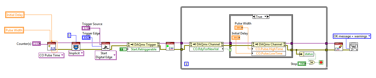
Sorry I forgot to mention: the Initial delay applies only to the first impulse of a redeclenchables generation. Every subsequent impulse will use low time as the Initial delay. I agree the behavior is not very intuitive (our latest guidance of series X actually supported an Initial period to allow on property Retrigger), but it is described in this knowledge baseand should also be mentioned in the DAQmx help.
As you generate just a single pulse, I would recommend simply connecting the Initial delay and at the entrances of low time to the same value for each pulse will be delayed further.
Exit tasks ongoing counter currently supports DAQmx writing. However, the finished generations or simple impulse are not. However, you should always be able to get the behavior you need with a property node DAQmx. The current solution on the series E/M is:
Again, this is not the most intuitive, but I checked that it works on my 6210. After writing a new value in the software the pulse will be updated on the 2nd trigger. Attached is the code stored in LV8.2.
Best regards
-
Registration of the analog inputs in continuous (Clipping)
Material:
(1) USB NI CDaq-9174 chassis
(2) NEITHER 9234 Analog Input Modules
(1) digital input module 9402 OR
Goal/Requirements:
To read the analog inputs continuous only in digital input is "high".
Problem:
Timestamp in log file prooves that logging is not continuous. It seems that the first seconds of 0.6 of every second is recording, I guess the other 0.4 is used to write custom? I can't use VI SignalExpress for this application because logging must be triggered by a high digital input.
File is attached. Thank you all!
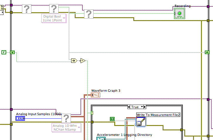
To detect changes in the digital input, you need to compare the current value to the previous. The easiest way to do this is to plug the output of digital playback on a shift register. The Boolean function involves will tell you when a transition has taken place. See the central part of the image below. If you exchange the true and the false case of case structures, you not the inversion function. Look at the help file for more information on what the function actually implies.
You must also change the wiring of the name of input for writing custom file FIle.vi so that the name is automaticlly changed. Depending on what you want the naming system to be, that it can be simple or rather complicated.
Lynn
-
Want a ramp of output voltage over time and measure input 2 analog USB-6008
Hello
I want to produce an analog voltage output signal that increases over time with a certain slope, which I'll send in a potentiostat and at the same time I want to read voltage and current (both are represented by a voltage signal) that I want to open a session and ultimately draw from each other. To do this, I have a DAQ USB-6008 system at my disposal.
Creation of the analogue output with a linear ramp signal I was possible using a while loop and a delay time (see attachment). Important here is that I can put the slope of the linear ramp (for example, 10mV/s) and size level to make a smooth inclement. However when I want to measure an analog input signal he's going poorly.
To reduce noise from the influences I want for example to measure 10 values for example within 0.1 second and he averaged (this gives reading should be equal or faster then the wrong caused by the slope and the linear ramp step size.) Example: a slope of 10 mV/s is set with a 10 step size. Each 0.1 s analog output signal amounts to 1 mV. Then I want to read the analog input in this 0.1 s 10 values)
Because I use a timer to create the linear ramp and the analog input is in the same loop, the delay time also affects the analog input and I get an error every time. Separately, in different VI-programs (analog input and output) they work fine but not combined. I searched this forum to find a way to create the ramp in a different way, but because I'm not an experienced labview user I can't find another way.
To book it now a bit more complicated I said I want to measure 2 input analog (one for the voltage of the potentiostat) signals and one for the current (also represented by a voltage signal) and they should be measured more quickly then the bad of the analog signal. I have not yet started with because I couldn't read on channel work.
I hope someone can help me with this problem
An array of index. You want to index the columns for a single channel.
-
What is the minimum response of analog input, through DSP online, output analog time?
Hello experts!
I want to know if it is possible to get a very quick response latency (~ 1 ms) sound recording (analog input), through online registration (DSP online), the presentation of his (analog output) processing, by using the DAQmx programming codes. My system of NEITHER includes NOR SMU 8135, SMU 6358 DAQ Multifunction controller and SMU 5412 arbitrary signal generator. I also have access to the latest version of Labview (2015 Version) software.
My project is on auditory disturbances, which inovles record vocalizations, manipulating the recorded vocalziations and then present the manipulated vocalizations. My current idea of how to achieve this fact triggered output voltage after reading the input using DAQmx Read samples. DAQmx Read output is filtered online and then passed as input for the DAQmx writing for analog output. For purposes of illustration, examples of code are presented below. Note for simplisity, codes for the trigger part are not presented here. It's something to work in the future.
My question here is If the idea above should be reaching ~ 1ms delay? Or I have to rely on a totally different programming module, the FPGA? I am very new to Labview so as to NEITHER. After reading some documentation on FPGA, I realized that my current hardware is unable to do so because I do not have the FPGA signals processing equipment. Am I wrong?
Something might be important to mention, I'm tasting with network (approximately 16 microphones) microphones at very high sampling rate (250 kHz), which is technically very high speed. Natually, these records must be saved on hard drive. Here again, a single microphone is shown.
I have two concerns that my current approach could achieve my goal.
First, for the DAQmx Read function in step 2, I put the samples to be read as 1/10 of the sampling frequency. It's recommended by Labview and so necessary to avoid buffer overflow when a smaller number is used. However, my concern here associated with the latency of the answer is that it might already cause a delay of 100 ms response, i.e. the time to collect these samples before reading. Is this true?
Secondly, every interaction while the loop takes at least a few tens of milliseconds (~ 30 ms). He is originally a State 30 late?
Hey, I've never used or familiar with the hardware you have. So I can't help you there.
On the side of RT, again once I don't know about your hardware, but I used NOR myRIO 1900, where he has a personality of high specific speed for the RT where I can acquire the kHz Audio @44 and process data. Based image processing is ultimately do the treatment on a wide range of audio data you have gathered through high sampling frequency and number number of samples as permitted by latency, please check this .
I lost about 2 weeks to understand host-side does not work and another 2 weeks to understand the even side of RT does not work for online processing (real time). Then, finally now I'm working on FPGA, where the sampling rate is 250 kHz (of course shared by multiple channels).
The complex thing with FPGA is coding, please check if the filter you want is given below as labview automatically generates some codes of some filters.
Most of them will work in 1 SCTL IE if your target has 40 MHz clock algorithm will run in 25 ns. That's what I was looking for, I hope you

See you soon... !
-
I added the gTranslate for Firefox extension. It is clearly shown in the list of current extensions that I have. I tried to place a shortcut icon on the toolbar at the bottom of the page module (back side where the page zoom-in/zoom icons are displayed).
Procedure, I used: right click on the empty space on the toolbar at the bottom of page module. Click "Customize". Opens the square shape of the icons, but I don't see anything for the extension of gTranslate, I could "drag / drop" on the toolbar of the add-on.
Ask for help with this issue.
gTranslate not icons. You must select the text, right-click and hover the mouse over the menu item translate... and wait that the translated text to appear. You can also change languages in the submenu, or alternatively via Firefox Tools (Alt + T) > Addons > Extensions, gTranslate Options.
-
Satellite L20-182: after installing the OS only USB 1.1 not 2.0
Hello, I am an owner of the model Toshiba Satellite L20-182.
Recently I did a format disk and installed Windows XP Professional with Service Pack 2.Unfortunately, the system detects USB as a version 1.1.
I find anywhere USB 2.0 drivers.Could you help me?
Hello
Why suggest that you have only the USB 1.1 and USB 2.0?
To my knowledge you will not find any special USB Toshiba drivers Toshiba page.
Each unit of Toshiba uses the current Microsoft Windows USB drivers and it s not necessary to install the special USB drivers.I assume that you have installed the operating system from the original CD of Microsoft and not the Toshiba back CD. Am I wrong?
In this case you must install all Toshiba drivers that are available in the right order. The chipset utility is very important! Generally, the chipset must be installed at the first stage.Please also check this Microsoft documents:
Availability of the updated Windows XP SP1 USB 1.1 and 2.0
http://support.Microsoft.com/?kbid=822603When you install Windows XP Service Pack 2, the USB 2.0 drivers do not appear to be updated
http://support.Microsoft.com/kb/873169 -
USB key mounted differently on the top of the page two USB ports
Mac Pro 6.1 (end of 2013), currently running 10.10.5 using a Lexar 128 GB USB 3 stick to the format ExFat.
When I plug the Lexar key into the slot at the top left of the Mac Pro USB, (reported as SuperSpeed USB 3.0 in report of the system Bus), it mounts instantly on my desk.
When I plug the stick Lexar on Mac Pro USB at the top right , (reported as Hi-Speed USB 3.0 in report system Bus) on the USB led blinks about 2 x a second - sometimes flashing a slightly different rate - then after about two minutes of this, he goes finally on my desk.
This behavior is expected, or should I take in a service call?
Yo have other USB devices connected to the other USB ports?
If so, disconnect those
-
It is possible to activate the "wake on USB" on a Satellite C870-142?
It is possible to activate the "wake on USB" on a C870-142, specifically the USB 3.0 port? In Device Manager the USB 2.0 root hub properties have the "allow this device to wake the computer" greyed out, while the properties of USB 3.0 root hub is not a power management tab. All have the latest drivers from Intel, not obsolete Windows Update ones.
There is no other choice that I don't see in the InsydeH20 BIOS, which is the latest update to version 6.80 site Toshiba drivers - I have not tried to find/load another version of BIOS. I want to install a USB adapter, Gigabit LAN, but should he Wake on LAN (who works with the NETWORK card internal fast ethernet). He has "allow this device to wake the computer" is checked, but I guess that's irrelevant if the USB port to which it is attached is not enabled.
In case this wake on USB feature isn t available and supported by the BIOS, you won't be able to use it.
Note: you cannot use any BIOS! You must use the BIOS available on the Web from Toshiba website. Use of other BIOS may damage the module EPROM and motherboard.
-
To input analog shutdown when the analog output is completed and synchronization
Hello
I'm trying to get my LabVIEW program to send analog output to a computer and read acceleration using the cDAQ-9184. Chassis output that I use is the NI 9263 and the chassis of entry is the NI 9234. I generate a signal of white noise using LabVIEW Express signal generator.
The first problem I have is the synchronization. I had an old VI that has begun to measure the acceleration just about a second after the entry has been given to the machine. I used the LabVIEW tutorial on how to sync the analog input and output, only to discover that it does not work with two different hunts. Then I found another tutorial that shows how to synchronize different frames between them.
The second problem is the cessation of the LabVIEW program. What I want to do is to generate the signal and then simultaneously send and read the input and output analog, respectively. It is because I don't want a phase difference or any shorter signal for a direct comparison. But as soon as the signal is sent to the machine, I want the entry to stop analog playback and then then the LabVIEW program must stop. I want to be able to choose any length of signal to be generated and stop as soon as the entire duration of the signal has been sent to the machine.
I tried 'DAQmx stop', "DAQmx Timer" and 'DAQmx's task made?' and none of them have worked for me. It is also my first time on a forum posting, so I hope I gave enough information. I enclose my VI as well. The VI shows I read an entry for the analog input voltage, but I am only using this to try to get to the work programme.
I'd appreciate any help I could get.
Thanks in advance
Peter
Hi Peter,.
I have some recommendations for you that I think you will get closer to your solution. First of all, I assumed you meant that you had 1 chassis (cDAQ-9184) who had two modules in it (NOR-9263 and NOR-9234). My next steps are based on this assumption, so if it's wrong, please let me know.
For your first question about the synchronization, the code you provided is very close to what you need. You need to do, however, implement architecture master/slave for startup tasks DAQmx functions. To do this, you can add another frame to the flat sequence structure and put the master start task (input voltage) after the start slave (output voltage) task.
To manage your second question and that the program ends at the point where you, the first step is to get rid of all the logic that you use with the local variable of length of time. Rather than use this logic, just wire the node "task performed?" of "is task performed?" operate to stop the loop. This will cause your loop to stop as soon as the signal is sent to the machine.
I have some other recommendations for you that will increase the performance of your program:
(1) rather than writing on file inside the last loop, you can use the DAQmx Configure Logging (PDM) .vi. You will place this VI between DAQmx Timing.vi and DAQmx Start Task.vi to the task of the analog input voltage.
(2) after the last while loop, you want to stop the task and analog outputs as well with another DAQmx stop Task.vi.
(3) rather than using a local variable for the entrance of displacement and wiring it in the DAQmx Write.vi, you can wire directly from the output waveform of the wave to build function node.
That should help you get started in the synchronization of these tasks.
-Alex C.
Technical sales engineer
National Instruments


Maybe you are looking for
-
Hello. Sometimes when I write, my message has a strange font, but I have not changed anything in the config. Here is an example: Why is this marked line different? Thank you
-
I want to show my x axis at a different scale than what is actually used to plot my data (conversion MHz at the time). It seems that TemplateValuePresenter is what I need but I can't find any documentation on this topic. I can get this to work usin
-
How to change the scanning resolution?
I have Windows 7 and HP 7520 four-in-one. The scanner offers resolutions of 75,100,200,300,600,1200 & 2400. How can I change these resolutions? I have a lot of different sizes of old photos and would like to change the resolution to 400 or 500 but ca
-
How to synchronize streams RS232 and GPIB in labview
Dear all, SOS. I built a system with 2 instruments GPIB and serial RS232 1 instrument. The VI works well with high light performance. But when I run the program normally with games step by step, what I get is only the stream GPIB. The serial data is
-
How to remove BlackBerry Smartphones BOOPSIE
I went to the salon here in Vegas for being able to download an application that allows you to map sellers want to see via an application called boopsie. The app was useless, and now when I go in my browser it's always there «Find with Boopsie» I l