LabVIEW Interface Kinect question
Hello. I hope someone can help with this problem. I try to get the Kinect Demo.vi LabVIEW and additional vi (from Kinect LabVIEW using Microsoft Kinect API Interface) to run on my system:
64-bit Windows 7 Professional SP1
LabVIEW 2011 w / Vision
Microsoft Kinect SDK (most recent)
.NET 4.0
I was able to get the vi to load without errors, but when I run it I get the error message attached.
7 error to the constructor of node in Kinect_API.lvlib:Initialize Kinect.vi-> Kinect_API.lvlib:Kinect Demo.vi
Possible reasons:
LabVIEW: File not found. The file may have been moved or deleted, or the path to the file would be incorrectly formatted for the operating system. For example, use- as Windows path separators: on Mac OS X, and Linux. Check that the path is correct using the command prompt or file Explorer. = OR-488: the non-existent GPIB interface.
Any help is appreciated.
Thank you.
Problem solved. I uninstalled the SDK Kinect (I think that's the important part) and .NET 4.0. Then reinstalled .NET 4.0 and the Kinect Beta SDK (not the most recent SDK of Kinect):
http://www.Microsoft.com/en-us/kinectforwindows/develop/beta.aspx
Everything works fine now. I had to go through the LabVIEW VIs and re - select a few .NET runtime calls, but everything works fine now.
Thanks for all the help.
Tags: NI Software
Similar Questions
-
LabVIEW Interface for installation of the Arduino
I want to install the LabVIEW Interface for Arduino Toolkit, so I can control an Arduino Uno R3. Say the instructions to download and install the VIPM and then you can download and install the Toolkit through the VIPM. The only problem is that workplace of our company doesn't have access to the internet for security reasons, so the VIPM will not be able to download the Toolkit. How can I download manually the Toolbox for a laptop without LabVIEW, save it on a usb key, then install manually on the workstation with LabVIEW? Any help would be greatly appreciated.
I asked the very question sometime back and here is the answer I received. I decided to use another computer on the network for the work of the Arduino, so I never tried what was suggested.
Let us know how it turns out.
-
Any camera regardless of the interface is available for use with the LabView interface.
Hello
I intend to go for some CMOS camera,
but I have a huge doubt before buying, the camera of menttioned above is not anywhere in this list. Nor can I see any type being supported USB device.
The question is
- is a camera regardless of the interface is available for use with the LabView interface?
- Can I build a VI to communicate with any device image and recording of camera and take the data?
Any kind of help or advice is greatly appreciated... I have to buy a CMOS camera and begin to run.
Thank you...
Hello Virginia,.
I am pleased that this information has been useful, one thing I wanted to mention is that USB 3.0 has its own standard USB 3.0 Vision which is currently not supported. If this camera is also Direct Show compatible then you will be able to acquire an image using IMAQdx and manipulate all the attributes that are published to the API Live Show.
I hope that USB 3.0 Vision will be supported in the near future, and we tentatively announced for this standard of communication for the August 2013 Vision Acquisition Softwareupdate.
See you soon,.
-Joel
-
LabVIEW interface with multiple blocks of Festo module
I am trying to connect with a block of Festo, but I can't. Here are the details:
I'm under Labview 2012 SP1 with IndComm-DeviceNet 2.2 pilot on a 64-bit Windows OS. I installed a PCI 8532 card NOR. I see the map to the MAX.
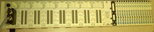
The block of Festo is built with the following Modules: CPX_FB11 (communications module), 4 analog input Modules, 1 Digital module, 2 digital modules followed by 32 Festo valves. (Image below)
Using DeviceNet PXIPCI Basics.lvproj I did the following:
In the project, right-click on desktop > New > targets and devices > existing target or device, discover an existing target or device...
Expand the node of DeviceNet Master Interface, DeviceNet1 chosen and added to the project.
A click on the newly added DeviceNet/device target > New > targets and devices...
Expanded the Festo Block "CPX_FB11" selected DeviceNet slave device and added to the project.
Initially, I received an error card technique 'EDS file no assigned' I solved this by following the direction listed here.
However, I'm unable to "see" anything other than the CPX_FB11 LabView. The tree view of the devices lists not analog, Digital e / s or valves. I can't operate the Valves and IOs digital or analog. When I run the entire project VI they then expire.
Any help would be appreciated.
Thank you
Tennessee Paul
Hi Jesse,.
I'm not entirely sure what the specific problem was. I kept getting strange behavior. Errors in LabView and on my camera from Festo. The EDS files change. So, I did as any natural born THERE would be worker, I rebooted.

Here are the steps I used to get this project going. In doing so, I found that to set up a DeviceNet device in LV2012SP1, no need to manually enter the data in file EDS. There is a tool to load files EDS. It dealt with issues I had in the previous Forum posts: here about loading files EDS in LabView and here regarding setting up a DeviceNet network.
Environment: Windows 7, 64-bit processor. IndComm 2.2 pilot. LabVIEW 2012 SP1
Starting with the example LabView project: "Devicenet PXIPCI Basic.lvproj.
Add a DeviceNet master to a LabView project
- The project: right-click on my computer
- Select new
- Select the targets and the device (s)
- Select the option "discover existing devices.
- Select the discovered device.
- Click 'OK' (Note: in this case, my master is a card PCI of NOR-8532)
Add a DeviceNet slave device to a LabView project
- Right-click on the master device newly added in the project tree
- Select new
- Select the targets and the device (s)
- Select 'discover existing devices.
- Select the discovered device.
- Click OK. (Note: in this case my slave is a block of Festo CPX-FB11.)
Load an EDS file to the slave device
- Right-click on the slave device
- Select "Sheet"... »
- Click on add files...
- Navigate to the location of the EDS file.
- Select the file.
- Click OK.
- In the left pane, expand the data sheet newly added up to reach the node displays the version.
- Select the version.
- Click OK.
Check the device and file EDS
- Right-click on the slave device
- Select utilities
- Select the Panel of Test online
- Select the option 'Device status' in the field of category on the left.
- On the right, select the slave device, you want to check.
- Click on "check the device".
- Read the errors/warnings or lack thereof.
- Navigate to the following location: C:\ProgramData\National Instruments\NI-IndComm for DeviceNet\Datasheet
- Remove the sheet (Note: there is more that one datasheet added manually.) Additional EDS files come with the IndComm driver. Find the EDS file for the specific device that you want to replace and delete).
-
VBAI Custom LabVIEW Interface minimum size limit
I have a LabVIEW VI selected as my custom VBAI interface. I intend to run VBAI on a PC that is also running an executable (developed in LabVIEW). Both the executable and VBAI have graphical interfaces that need to remain visible during operation. With limited screen real estate, I'm doing the interface VBAI just a little smaller, but it seems to me running a form of minimum window size limitation. When I resize the window VBAI it appears to a larger size. I have not set this restriction on the LabVIEW VI that is used by VBAI, so it must be a restriction in VBAI itself.
- Can I change the minimum size?
- If it is not editable, it seems somewhere in the documentation? What is the minimum window size?
Thank you
Dan press
Hello Dan,.
VBAI has a minimum resolution of 1024 x 768, less a strip at the bottom of the toolbar, and unfortunately you can not change the minimum size for VBAI. Let me know if this answers your question!
-
Problems with arduino labview Interface
I have the labview-arduino interface, but the problems came when I run the program, sometimes it work perfectly, but sometimes (almost all the time), I can not connect this time, the series of programs and do not show any kind of problems, I can see that in the resourse computers two visa, I don't know if it's because she I soppose comunication , but my arduino do not work, and I can use perfectly with the arduino IDE, but not with VISA, I used the Arduino IDE to be shure that works my Arduino board
so if you know how to solve this problem, please help me!
Thank you!
There is no need to host files somewhere else. Feel free to download on the forums and attach them to your message.
Minor first comments. Why are you re-reading your every 2 seconds config file? Expect you to change? If it is then played once and not proofread.
I think it would be better if you stopped when an error occurred, you can do this by wiring to the RO error enter the stop condition, or use the arithmatic composed with gold.
But I think the main question you have, it's that your Arduino reference may be whipped out if you do the wrong things. If your equal comparison is false, you go to the wrong case, where you are not passing the arduino reference. So when you go to close you don't close your reference and your equipment will always be open, and you try to run again will result in an error. For even if your loop runs for 0 iterations your reference is lost. An updated version, which has some of these changes is attached.
-
Solenoid with labview interface
Hi, I currently have a solenoid valve (NVZ110) with 24 VDC, "+" and "-" terminals) and I:
CFP-DIO-550
CFP-AO-200
CFP-AO-210
PSC-HAVE-112
My question what module should use to open and close the tap? Also, I couldn't find a tutorial on how to create a simple vi to control this valve using LabView. Is there a simple example VI?
As an alternative, you can use the 550 to turn on a mechanical or relay DC coil, whose output contacts could then apply/remove you power AC powered solenoid.
-AK2DM
-
Change the path open the initial sequence of the operator Simple of TestStand with LabVIEW Interface
Hello
I use an Interface with LabVIEW TestStand operator similar to the TS IO Simple example.
But I want to change the path when you click the button open the sequence file, I want a specific path.
Any help is apreciated.
Kind regards
Daniel Coelho
Daniel, you might be interested by this Knowledge Base:
How can I change the default directory for the open file dialog box in TestStand?
I searched ni.com for teststand of dialog box open the file and it was the fifth or so link.
-
LabVIEW interface with micro contoller
I'm new to labview. I need to know if the DAQ card is necessary to interface with micro controller? If no need then one can you explain how inter face microcontroller 89c 51 with Labview... If necessary, explain how interface?
JEAN ASOKAN
-
Launch the operator of TestStand, LabVIEW Interface via ActiveX
Hello
I create a simple VI in which I select a product in a list number and press Go. The VI is used to ensure that the most recent sequence file is open and is not inteneded to replace the OI, simply start with a single click.
I don't know that I am takign the right approach at all, that I know very little about ActiveX, but am trying to learn! When I run the VI, I am prompted to select a file sequence and connection, and that's all. TestStand windows never appears. It's just a setting that is incorrect, or will the approach I take work, as I am access API instead of just opeing the application?
I removed all the extra features (dropdown list, the configuration file, etc.) from the code included as it works very well.
Any help would be appreciated.
Kevin
What you do are from TestStand without the interface, and then you set the sequence to use. I think that there is another necessary step indicating the sequence to start really and not only the application.
It looks like no this is what you want to do, because the intention is that you can then use these tools ActiveX to create sequence files, or run them, without running the sequence editor which is what you normally see when you run TestStand.
I've never tried, but you can look at this article on the launch of sequence files from the command line which allows to LabVIEW.
http://digital.NI.com/public.nsf/WebSearch/146D372C1F807E6D862567E7004881AB?OpenDocument
-
Issue of the user of LabVIEW interface
Hi guys:
I have two question about LV user interface design:
Referring to the generation of the LV application:
1 How do I hide the runing mode menu bar
2 How do I change the title, I mean, usually the title of the application window is "xxx.vi", I can change it?
Thank you
You can mark as solution has agreed to close the thread
-
ASA "route inside 0 0 192.168.1.1 by tunnel" interface ACL question
Hello
Small question around the road inside 0.0.0.0 0.0.0.0 192.168.1.2 in tunnel command.
Do you need to add a u-turn traffic within the ACL interfaces (for example internet related http traffic) or 'same-security-traffic permit intra-interface' negates the need of this?
So if my site remote vpn outside is 10.1.1.0/24 should I add entering permitted statements for the 10.1.1.0/24 inside my interface.
Thank you
same-security-traffic permit intra-interface allows then-input-output traffic on a single interface
allowed incoming 10.1.1.0/24 statement in the list ACL allows traffic (output - then-) penetration on a single interface, but you must disable the RPF check
-
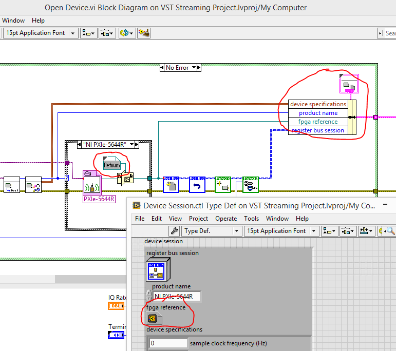
I play with a VST 5644 and model VST streaming. On the FPGA VI, I added the code, then added an indicator of the face before of the FPGA VI and compiled. Executes the FPGA VI in interactive execution mode, the indicator works well. Side host, however, I can't access the new indicator with read/write control.
Coming out of the open FPGA VI reference I can see the indicator on the wire, but in the Dynamic Cast of Interface FPGA function is have rooted out the refnum somehow. If I connect to control read/write directly to the output of the function of open reference I can access the indicator very well.
No idea what I am doing wrong?
Thank you.
You re-configured your FPGA VI reference with the new bitfile interface? The cast of dynamic interface defines the lead as all methods and indicators according to the type of wire connected. You can right click on the constant of type and select "Configure the FPGA VI... of reference". In the pop up window that follows, select "import of bitfile...". "and select the new bitfile you've built.
You must update the fpga reference type in the "Device Session.ctl" type def as well. This is the type that you will be able to access throughout the project.
-
LabVIEW fundamentals test question
Hello
I have attached a question on the test of fundamental principles of LV. The reasoning cannot understand if the answer must be A or b. Any help is appreciated?
Thank you
ABM
Could at least spell my name correctly?
Say that the improbability is low is not at all like saying that it is impossible. It would be unlikely to switch the 19 heads in a row, but the probability that the next draw is still 50-50.
I agree that the correct answer is B, but like many in questions that I saw, the answer has doubts and should be rewritten.
-
User interface simple Question
I apologize in advance for the simplicity of this question is probably, but I can't seem to find a way to do it.
I want to show a label that is framed with a value that is justifield just so that the labels are all on the left and the values are all right on the left.
I tried:
 HorizontalFieldManager row1 = new HorizontalFieldManager();
        LabelField l1 = new LabelField("Linked:  ");
        LabelField l2 = new LabelField(
                (theApp.getIsLinked()?"Yes":"No),
                Field.FIELD_RIGHT);

        row1.add(l1);
        row1.add(l2);
        add(row1);
That did not work. I also tried a few other things but can't seem to make it work.
Thanks in advance.
Here you go:
HorizontalFieldManager Row1 = new HorizontalFieldManager();
LabelField l1 = new LabelField ("Linked:", LabelField.FIELD_LEFT);
LabelField l2 = new LabelField ("No.", DrawStyle.RIGHT |) LabelField.USE_ALL_WIDTH);
In my case I had errors in my EDS file. Basically the slave device was not defined for the correct number of bytes of input/output in the EDS, i.e. a wrong configuration file. To fix this I had to change the EDS file.
Edit the file EDS
To change the EDS file, I used EZ-EDS , which is a freeware, devicenet specific EDS editor of ODVA.
I did my corrections and saved my file EDS. (After having saved my original, of course).
Remove the installed Labview EDS file
I restarted LabView.
I went through the steps above again and loaded my new EDS file.
I saved the project and came out of LabView.
I rebooted the computer and the slave device.
I restarted the project and launched a VI.
I was able to communicate with the device. That is something that I had not been able to do before. And, in doing so, I discovered how the device speak and why were not each module. (I have a standard for my block devices EDS file, as it appears that LabVIEW is not capable of a modular system that requires an EDS file for each module. I could be wrong on that last part though, as there may be a setting on my real device. But it is unecssary in my project. So I do not consider this further.) Because I was using a standard file of the EDS, only a single slave device showed, and so the data for each module are in the stream of bytes returned to the DeviceNet network. Addressing each module is a question of analysis the bits and the bytes appropriate.
Thank you
Tennessee Paul
Maybe you are looking for
-
Apple stores in the Canada, they do a free diagnostic as in the USA?
The stores Apple, service engineering, doing a free diagnosis, as they do in the USA? Are they reliable - can - we be assured the job is really necessary?
-
Drum kit designer-missing battery
Hello, I was messing around with the drum kit designer and I was wondering if perhaps some of the kits have not been correctly downloaded. I have no other options for the toms and just a few options for the other drums. I checked the audio library Ma
-
3-year next day guaranteed business registration on-site
Hello I bought an extended warranty for my laptop, it is a guarantee of 3 years next business day following service. Now, I tried to sign up for the service and it reqognized of certificate number I gave. But when I got to put in my serial key, addre
-
HP envy 5532: connection problem
I recently bought an hp printer for my iPad. No problem it connected and worked very well to the first impression, but I tried my Tablet yesterday and he told me no printer found air. Tried everything to work but nothing works. Becomes very angry.
-
all-in-one photosmart B110a: windows 10 and b110a
I had my B110 series all in one printer works fine for over a year, then I updated to Windows 10 and he stopped scanning. So I tried to remove and reinstall all the HP programs, tried to hook up with cable (as well as wireless), tried Hp trouble shoo