Layer 2 multicast configuration?
Hi all, my past and all experience what I read there is no additional configuration for multicast to work when the receivers and the unit which is PIM are in the same subnet? Is this correct?
I have a subnet of PBX and voice. The device that is running PIM is in the same subnet as my receivers (phones) are in. However, my phone dude tells me that I need to enable multicasting additional functions for phones do.
I enabled multicast in the past on some of my 3 layer devices, but, only when the device attempting to send multicast packets moving between subnets, such as imaging software.
Are there additional configuration, I need on my switches, they are all the basis of Cisco 3560 LAN switches.
Are there troubleshooting tips I can do on the switches to show upcoming multicast packets or not inheriting from the receiver?
Thank you
Dan
Hi Dan,.
Indeed, the Cisco Catalyst switches require no additional configuration to move within a VIRTUAL local network multicast, and by definition, no additional mechanism is necessary for a multicast should be flooded through a VIRTUAL local network.
However, the switches Catalyst running IGMP Snooping by default, and it is possible (but not certain) that this could be the cause of trouble. IGMP Snooping is trying to optimize flood multicast by learning about connected receivers and the multicast groups that they have subscribed to and then reference the multicast only through these switchports that have receptors for the corresponding group connected to them. IGMP Snooping depends on the presence of a multicast router in a local VIRTUAL network for sending periodic IGMP Membership Query messages. If this router does not exist, IGMP Snooping is expected to remain quiescent, but experience has been uneven, sometimes.
Then you can try to disable the IGMP Snooping on your switches just in case by simply entering the no ip igmp snooping in the global configuration mode. This will not cause any failure in your normal operation of the network.
If it doesn't then please give us some stream information (source, destination group) multicast as well as the exact symptoms that you are experiencing.
Best regards
Peter
Tags: Cisco Network
Similar Questions
-
MS NLB Multicast configuration on Cisco Bladecenter switches mode
We seek to MS NLB Multicast configuration on Cisco Bladecenter switches mode. We are adding static ARP and CAM entries for each port on the switches kernel that
the Bladecenters are connected to, or just the port of the virtual machine arrives at
push traffic at this time here? If we add it to a single port,
How vmotion will work... because it seems that we have to manually
transfer the arp from one port to the other entry.
We add the static ARP entry to the entire Cisco switch. If you can VMotion VMs NLB to another host that is physically connected to another switch, then this switch have thus added ARP entry. We have not tested the configuration only on the specified ports. But if you do, make sure that you include all the ports connected to the physical switch (if for DS you have four natachasery configured in a vSwitch...).
Here's a guide to how we have configured it several times in our society.
-
Detected incorrect configuration error - problem of multicast?
I saw a mistake 'Has detected a misconfiguration' after scoring in the Web client, select a cluster, the tab manage, settings, Virtual SAN subtab-> general. He went after activating the traffic on the vmk0 VSAN management interface. I found that by vSphere 6.0 Documentation Center, 'Network Misconfiguration in a Virtual SAN Cluster status' it was probably due to a bad configuration of the multicast.
I talked to my network admin, who made sure IGMP Snooping has been disabled, and I turned off VSAN, then again once and the error disappeared temporarily. However, when you choose inside on a specific host a cluster, I still see "host cannot communicate with all other nodes in the active SAN virtual cluster. The "Misconfiguration detected" error is returned.
1 is a multicast group must be configured to work? I am referring to vSphere 6.0 Documentation Center, "Modes of filter Multicast", where it is said:
Filtering basic multicast mode a Standard switch or Distributed Switch vSphere vSphere transmits multicast traffic for virtual machines based on the destination MAC address, of the multicast group. When you join a multicast group, the guest operating system pushes the MAC address of the multicast group down to the network through the switch. The switch saves the mapping between the port and the destination multicast MAC address in a table of local transfer.
I guess that does not apply to the VLAN that I've dedicated to VSAN multicast traffic, where IGMP Snooping should be disabled?
2 cannot not set port 4095 to enable all the VLAN resources shared - is it necessary?
I thought that when you configure the network on the ESXi server, I thought I should specify 4095 to VLANS allow all trunking 802. 1 q VLAN through.
As:
-the documentation I found only goes to 4094 and
-in the ESXi console, I entered 4095 to the VLAN ID (which failed),
is the VLAN ID of the management network is good? Or could it be that traffic for that VLAN even get through on the server because of this?
3 here is what I understand VMware in terms of this error:
Cluster form--nodes will not be able to communicate - Has detected a misconfiguration
– Option 1 -Disable IGMP Snooping = > allows to all the through the multicast traffic
– Option 2 -Configure IGMP Snooping Interrogator = > if there is another multicast traffic and you fear that multicast traffic could flood network
I also had this link to what is required by the side of Cisco, but it does not (gives 404 error). Can someone give instructions that work?
4. by comparing the results of two servers, they cannot ping each other (addresses 10.27.98.7 *) on vmk1. My network engineer said that the switchports are that all configured the same. Any thoughts on why they can't ping?
[root@host05:~] esxcli ip interface ipv4 network get
DNS name IPv4 address IPv4 subnet mask IPv4 address Type DHCP broadcast
---- ------------ --------------- -------------- ------------ --------
vmk0 10.27.98.199 255.255.255.192 10.27.98.255 fake STATIC
vmk1 10.27.98.71 255.255.255.192 10.27.98.127 fake STATIC
vmk2 10.27.98.136 255.255.255.192 10.27.98.191 fake STATIC
[root@host05:~] vmkping - I vmk1 10.27.98.71
PING 10.27.98.71 (10.27.98.71): 56 data bytes
64 bytes from 10.27.98.71: icmp_seq = 0 ttl = 64 time = 0,096 ms
64 bytes from 10.27.98.71: icmp_seq = 1 ttl = 64 time = 0.084 ms
-10.27.98.71 - ping statistics
2 packets transmitted, 2 packets received, 0% packet loss
round-trip min/avg/max = 0.084/0.090/0.096 ms
[root@host05:~] vmkping - I vmk1 10.27.98.70
PING 10.27.98.70 (10.27.98.70): 56 data bytes
-10.27.98.70 - ping statistics
3 packets transmitted, 0 packets received, 100% packet loss
[root@host05:~] vmkping - I vmk1 10.27.98.71
PING 10.27.98.71 (10.27.98.71): 56 data bytes
64 bytes from 10.27.98.71: icmp_seq = 0 ttl = 64 time = 0.088 ms
64 bytes from 10.27.98.71: icmp_seq = 1 ttl = 64 time = 0,074 ms
64 bytes from 10.27.98.71: icmp_seq = 2 ttl = 64 time = 0,081 ms
-10.27.98.71 - ping statistics
3 packets transmitted, 3 packets received, 0% packet loss
round-trip min/avg/max = 0.074/0.081/0.088 ms
[root@host04:~] esxcli ip interface ipv4 network get
DNS name IPv4 address IPv4 subnet mask IPv4 address Type DHCP broadcast
---- ------------ --------------- -------------- ------------ --------
vmk0 10.27.98.198 255.255.255.192 10.27.98.255 fake STATIC
vmk1 10.27.98.70 255.255.255.192 10.27.98.127 fake STATIC
vmk2 10.27.98.135 255.255.255.192 10.27.98.191 fake STATIC
-10.27.98.70 - ping statistics
3 packets transmitted, 3 packets received, 0% packet loss
round-trip min/avg/max = 0.072/0.080/0.089 ms
[root@host04:~] vmkping - I vmk1 10.27.98.71
PING 10.27.98.71 (10.27.98.71): 56 data bytes
64 bytes from 10.27.98.71: icmp_seq = 0 ttl = 64 time = 0,726 ms
64 bytes from 10.27.98.71: icmp_seq = 1 ttl = 64 time = 0,362 ms
64 bytes from 10.27.98.71: icmp_seq = 2 ttl = 64 time = 0.561 ms
-10.27.98.71 - ping statistics
3 packets transmitted, 3 packets received, 0% packet loss
round-trip min/avg/max = 0.362/0.550/0.726 ms
PS: this certainly looks like a network configuration problem
-
VSAN interrogator multicast with igmp snooping active requirement
When the switch is "igmp snooping" enabled, I do not understand why VSAN Articles and book require a mrouter or interrogator to define.
Nexus switch igmp debugs and newspapers, VSAN will send members unsolicited reports every 90 seconds at the address of the group 224.1.2.3 and 224.2.3.4. It is without worrying whether or not we have configured for VLAN mrouter or igmp snooping querier. As long as VSAN is coded so as to send the membership periodically reports, should we not there so a "questioning" on the virtual LAN to send Group/General requests.
As in my tests, I have no igmp mrouter or defined vlan VSAN and VSAN applicant all communicate are good with igmp snooping enabled (default for NX - OS).
DIA-N5K-02 # show ip igmp snooping-history of events vlan. I have 10.16.127.111
2014, August 5, 21:31:46.915356 igmp [3465]: [3917]: SN: < 127 > v2 received report: Group 10.16.127.111 on Eth1/21 224.2.3.4
2014, August 5, 21:31:46.915011 igmp [3465]: [3917]: SN: < 127 > v2 received report: group 224.1.2.3 10.16.127.111 on Eth1/21
2014, August 5, 21:30:17.037868 igmp [3465]: [3917]: SN: < 127 > v2 received report: Group 10.16.127.111 on Eth1/21 224.2.3.4
2014, August 5, 21:30:17.037606 igmp [3465]: [3917]: SN: < 127 > v2 received report: group 224.1.2.3 10.16.127.111 on Eth1/21
2014, August 5, 21:28:46.950748 igmp [3465]: [3917]: SN: < 127 > v2 received report: Group 10.16.127.111 on Eth1/21 224.2.3.4
2014, August 5, 21:28:46.950273 igmp [3465]: [3917]: SN: < 127 > v2 received report: group 224.1.2.3 10.16.127.111 on Eth1/21
2014, August 5, 21:27:17.073420 igmp [3465]: [3917]: SN: < 127 > v2 received report: Group 10.16.127.111 on Eth1/21 224.2.3.4
2014, August 5, 21:27:17.073042 igmp [3465]: [3917]: SN: < 127 > v2 received report: group 224.1.2.3 10.16.127.111 on Eth1/21
2014, August 5, 21:25:46.985909 igmp [3465]: [3917]: SN: < 127 > v2 received report: Group 10.16.127.111 on Eth1/21 224.2.3.4
DIA-N5K-02 # show ip igmp snooping vlan 127
IGMP Snooping information vlan 127
IGMP snooping active
Search mode: IP
Optimized multicast Flood (OMF) disabled
Applicant IGMP no
Switch-interrogator disabled
Tracking explicit IGMPv3 is enabled
IGMPv2 leave quickly disabled
Delete report IGMPv1/v2 on
Disabled removal of IGMPv3 report
Removing local groups link activated
Detection of router port using PIM Hello, queries IGMP
Number of ports in the router: 1
Number of groups: 2
Function of vPC VLAN enabled
Active ports:
Eth1/21 Eth1/22 Eth1/23 Eth1/27
Ros
DIA-N5K-02 # show ip igmp snooping groups vlan 127
Type: S - static, D - dynamic, R - port of the router, F - Fabricpath base port
Group VLAN address worm Type port
127 */* - R Po1
127 224.1.2.3 v2 D Eth1/22 Eth1/21 Eth1/23
Eth1/27
127 224.2.3.4 v2 D Eth1/21 Eth1/22 Eth1/27
Eth1/23
We found that for some providers of network switch, an interrogator is required when you enable IGMP snooping. If espionage works without an interrogator for your specific provider, then this is ideal. In all cases, we recommend that you consult your provider for their specific recommended configuration of switch of layer 2 multicast switch.
-
Agilent N6702A - error in the configuration of Channel 4
Hi guys,.
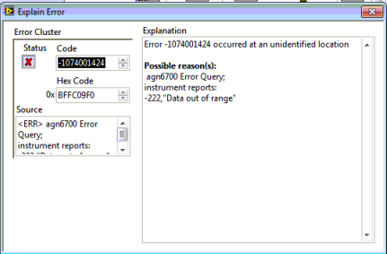
I use Agilent N6700 LabVIEW drivers for the configuration of the instrument. I am able to set up the first whithout 3 channels any problem, but when I try to configure the Channel 4, he throws and error - 222 "" Data Out Of Range '. " I am able to configure Channel 4 physcally on the instrument, but not of LabVIEW.
All the world is facing this problem?
Any help would be appreciated.
Kind regards
NitzHey guys,.
I thought kind of the issue myself. Channel 4 was grouped with channel 3, in which case, only the lower layer (ch3) is configurable which inturn will set up the group. Missed me the point that I found in the data sheet.
Thank you all who have looked into this post and tried to help him.
Kind regards
Amine31 -
Problem of layer 3 of SGE2010 with installing intervlan routing
I'm new to the switches for small businesses and could use assistance in the configuration of routing for intervlan between several VLANs on the switch. I changed the 3 layer mode and configure the VLAN. When I enter an IP address for VLAN2, I disconnect (VLAN1 ip) configuration on the switch interface and I can't access the switch unless I reset it. I tried several times and each time it has the same. Is there something else I need installation before you configure the ip address for other VLANs?
Hi Jacqueline,.
Thank you for your participation in the community of support to small businesses. My name is Nico Muselle of Cisco Sofia HWC.
This is the normal way for the switch to behave. There are 2 ways to work around this problem.
- You assign a port to the VLAN2. After the configuration of the IP address, you connect your PC to this port and make sure that it is in the same subnet as the address IP 2 VLAN.
- You assign a static IP address for the vlan by default first and make sure your connected PC is in the same subnet.
The reason for this behavior is that the switch has its DHCP client enabled, if no DHCP server is available, it will return to its default IP 192.168.1.254 (which I assume that you connect to the configuration).
However, once you set up a static IP address on the switch, the DHCP client and the default IP address is disabled, which means that the obtained from DHCP or the default IP address 192.168.1.254 are more accessible.
I would go to step 2, because it's the simplest solution to your problem and you would like a default static IP VLAN in any case, I guess.
I hope this helps!
Best regards
Nico glacier
Senior Network Engineer - CCNA
-
Domain name for the IP and EBS r12 changed the configuration
Dear all
I have oracle ebs r12 installed on the development server on 64-bit linux OEL, I changed my domain name and IP address of this server. Please help me how to change this configuration to the instance of the EBS. When I run adstrtal.sh apps/apps his mistake to see the
opmn id = hostname.domain.com:6200
No matched process or applications.
domain name shown above is old it is changed. name of domain and IP is changed no host name.
Please advice how to retrieve.
AbdelouahedDid you complete the steps described in these documents?
Note: 338003.1 - how to change the host name or port of the database layer using automatic configuration
Note: 341322.1 - how to change the hostname of a stream of Applications using automatic configurationAdditionally, make sure that you clean the FND_NODES table according to the (how clean non-existent nodes or addresses IP of FND_NODES [260887.1 ID]).
Thank you
Hussein -
Hello Hussein.
I just want to clarify the installation set-up for configuring shared with the following scenario
-11.5.10.2 application version
-db 10g r2 version
-application layer (RHEL5 - 32 bit) db level (RHEL5 - 64-bit).
During installation, can I directly use the software 32 bit 11i to install the db node and the application node? Start the installation on the db layer and then on the application layer, knowing that the installer is 32 bit and my db server is 64-bit. Or I need to install the first (apps and db) in Server 32 bits and then later migrate the PB Server 64-bit? (which will take a long time) with the following doc id: using the Oracle Applications with a layer of database Configuration from Split on Oracle 10 g Release 2 [369693.1 ID]
For some reason, we always have to use 11i on this implementation.
Thank you very much for your help.
Kind regards
JeffHi Jeff,
During installation, can I directly use the software 32 bit 11i to install the db node and the application node? Start the installation on the db layer and then on the application layer, knowing that the installer is 32 bit and my db server is 64-bit.
Yes you can, but your database will be 32 bit running on 64-bit operating system, you must migrate the base data and then to 64-bit.
Or I need to install the first (apps and db) in Server 32 bits and then later migrate the PB Server 64-bit? (which will take a long time) with the following doc id: using the Oracle Applications with a layer of database Configuration from Split on Oracle 10 g Release 2 [369693.1 ID]
You can do it too.
Personally, I'd go with the second approach.
Thank you
Hussein -
How to move and resize an entire layer with different objects and groups
OK, I'm a little confused here. Things don't work the way I thought they would be and the documentation has confused me more.
I currently have in my code
var embedLeftSleeve = new File(folderPath+"/LeftSleeve.ai");
var leftSleevePlaced = doc.groupItems.createFromFile (embedLeftSleeve);
leftSleevePlaced.top = currentHeight;
leftSleevePlaced.left = 0;I am importing a file HAVE and try to put it in its own layer. I want that it (the file imported AI) in its own layer. And I want the layer to be configured exactly as it was in the original. But, after importation, it seems to group non-grouped items, some items do not display the same way they have (like a shape with a gradient in there).
And finally, I want to all the elements are resized to this layer as if I have selected the layers in illustrator and put across the hand (but it script on a defined scale).
Can someone help me please. I am digging deep into the documentation and searching everywhere online to find what I want with little chance.
John
Yes Im getting problems with a met unknown shading type. Take this mixture on and everything else seems in good condition.
-
I have read these forums and noticed that many people have problems with multicast configuration. Basically, problems are bandwidth floods, no interrogator, confusing the router pim configuration...
In addition, ive seen some promisses of technical stuff that next gen linksys switches will have #ip igmp snooping inquiringly, as cat. so I am interested if anyone can give me the answer.
It's an interesting question for a lot of people who wouldn't be expensive switches chat for this kind of simple use.
Kind regards
David
Hi David,
You have much more options as seen in the GUI, so I though I'd put as simple network together and run you through a validation.
But I guess you have the updated version of the switch SRW224G4P called SRW224G4P-K9-NA.
If you have the old switch what follows is irrelevant for you.
I implemented a simple network diagram showing my simple network topology used during my wee test;
I chose the RV042 as my router from Layer 3 in this network.
It was really to provide DHCP services, but shortly after that all devices have IP addresses, I removed the RV042, becauise, I noticed he was sending IP IGMP General queries. Something that I didn't have in the next test.

I was using a software based multicast Tester, produced by the wonderful people at Twisted Pair Solutions. This software can send or receive multicasts to a defined group, and that correctly meets General IGMP queries. I'll call this software MCT (multicast test).
I got the software MCT on PC C. PC C is connected to the switch 10 port, it sends the multicasts in the switch at a rate of about 10 packages of multicast a second.
I got the software MCT on PC PC a. is plugged into the switch port 1. She is set to receive and count of multicasts from switch
I got B PC connected to the switch port 2. PC B check switch statistics, but do not try to receive multicasts of 3 PC.
I had Setup multicast snooping on VLAN 1 and mark according to the screenshot of GUI.
Note: I had only one vlan on the switch.

In a composite of two screenshots below, you can see that the status between the IGMP queries is enabled.

I removed the RV042 out of the network, because I noticed in an on PC A wireshark capture, the RV042 sent General group queries. I wanted to switch to reprise this role
I waited a few minutes and only displays the igmp activity.
It can be clearly seen in the screenshot below;
- Switch series SG300 sent General queries (2 minutes) of the IP source 172.16.1.100.
- He waited for the general query router mcast, but when none came, 60 seconds later sent it's own general request. Fair enough, he had to assume that a router mcast can send general queries every minute.

Statistics of the switch can be seen below, it showed.
- B PC on the switch port that G2 was not invaded by the multicasts, in other words snooping works;
- Port 10, PC C sends to 2962 of multicast to switch packets.
- Port 1, PC A 2900 receives multicast switch packets
- port 2B, PC is not part of the multicast group 234.55.66.77 and as such is not invaded by the multicasts.
All three PCs are windows based products, and some of the multicasts emanate from these devices.
See the interafce County property
Port InUcastPkts InMcastPkts InBcastPkts InOctets
---------------- ------------ ------------ ------------ ------------
gi1 12 9 6 3493
247 237 6 43733 IG2
gi3 0 0 0 0
gi4 0 0 0 0
gi5 0 0 0 0
gi6 0 0 0 0
gi7 0 0 0 0
gi8 0 0 0 0
gi9 0 0 0 0
GI10 26 2962 3 850881
gi11 0 0 0 0
gi12 0 0 0 0
gi13 0 0 0 0
gi14 0 0 0 0
gi15 0 0 0 0
gi16 0 0 0 0
gi17 0 0 0 0
gi18 0 0 0 0
gi19 0 0 0 0
gi20 0 0 0 0
gi21 0 0 0 0
gi22 0 0 0 0
gi23 0 0 0 0
gi24 0 0 0 0
gi25 0 0 0 0
gi26 0 0 0 0
gi27 0 0 0 0
gi28 0 0 0 0
Port OutUcastPkts OutMcastPkts OutBcastPkts OutOctets
---------------- ------------ ------------ ------------ ------------
Article IG1 13 2900 9 839691
IG2 233 9 90453 343
gi3 0 0 0 0
gi4 0 0 0 0
gi5 0 0 0 0
gi6 0 0 0 0
gi7 0 0 0 0
gi8 0 0 0 0
gi9 0 0 0 0
GI10 24 343 12 47165
gi11 0 0 0 0
gi12 0 0 0 0
gi13 0 0 0 0
gi14 0 0 0 0
gi15 0 0 0 0
gi16 0 0 0 0
gi17 0 0 0 0
gi18 0 0 0 0
gi19 0 0 0 0
gi20 0 0 0 0
gi21 0 0 0 0
gi22 0 0 0 0
gi23 0 0 0 0
gi24 0 0 0 0
gi25 0 0 0 0
gi26 0 0 0 0
gi27 0 0 0 0
gi28 0 0 0 0
If I look at the groups of multicast on switch, it shows that only two ports were involved in the 234.55.66.77 multicast group. This is the correct behavior.
switch4cf17c #sh ip igmp snooping group
Group VLAN Source include Ports Ports Exclude Comp.
Address mode address
---- ------------ ------------ -------------------- -------------------- -----
1 234.55.66.77 * article IG1, gi10 v2
1 239.255.255. * gi1-2,gi10 v2
250
Just to complete the display, here's the CLI command (highlighted) to enable the feature in the interrogator on the switch.
[Kswitch4cf17c #sh run
Bridge multicast filtering
IP igmp snooping
IP igmp snooping vlan 1
applicant ip igmp snooping vlan 1
interface vlan 1
172.16.1.100 IP address 255.255.255.0
output
interface vlan 1
no ip address dhcp
output
hostname switch4cf17c
No complexity of passwords allow
No server snmp Server
The telnet server IP
Hope this helps you and others
Best regards, Dave
-
VMWare ESXi 5.1 promiscuous mode.
Hello
I installed VMWare ESX5.1 and I created several machines virtual v.7 on it.
All virtual machines are same vSwitch and the Group of ports that are configured to reject the promiscuous mode.
The problem is that if I dump the traffic from the vMachines I CAT see ANY traffic is originating and destined to other virtual machines.
I used tcpdump to dump the traffic like this:
tcpdump-i eth1 hosts not < my_laptop_ip >
And I see stuff like this:
IP 16:03:45.386981 192.168.19.108.http > 2.194.11.124.51972: P 40724:41157 (433) ack 1189 win 175
192.168.19.108 is the IP address of another machine in the same ESX.
Is this normal?
Thanks in advance
The destination is a layer 2 multicast MAC, entirely explains why the other machines virtual in this VLAN see all outbound traffic that is routed on this router. Note that you should not see any incoming frames from the router, as destination of these frameworks MAC would be the unicast MAC of the respective virtual machines.
Also, the physical host on your network computers would see all this traffic like VMs unless your firewall send reports of IGMP Membership and you have IGMP snooping enabled on your layer 2 switches.
So the behavior you're seeing basically is "perfectly normal", side vSwitch/layer 2.
That being said, mind telling us what kind of firewall or clustering do you use? What is some active firewall cluster that requires multicast? In all cases, the vendor 01-00-5e ID matches IPv4 multicast addresses. You seriously use a multicast IP (for example 224.x.x.x) as your default gateway in this subnet? I'm pretty sure that's not how things are meant to work in the world of IPv4.
-
NEITHER 9852 communication with fault tolerant CAN materials
Hello
I have a cRio 9074 and recently bought a module NI 9852 2-port low-speed/fault-tolerant CAN.
It's my first attempt at network comms in cRio and I realized that none of the devices with that I want to communicate are immune to failures and fault-tolerant physical layer requires different endings to 'normal' high speed MAY (immediately after I broke the seal on the box, of course!)
Is it possible that I can configure the physical layer for this configuration to work reliably (alebit to)< 125="" kbps="" and="" with="" no="" fault="">
Kind regards
Chris
I'm sorry. The low speed / transceivers and breakdown-tolerant high speed MAY use different communication protocols.
HS CAN is recessive when CANH and CANL are both to nominally under 2, 5V. It is dominant when CANH is 3.5V and CANL is 1, 5V.
LS CAN is recessive when CANH is a CHANNEL and 0V to 5V. It is dominant when CANH is 3.6V and CANL is 1.4V.
You can see that they are almost the same for the dominant, but different for recessive. In addition, the sequence of end between two buses is different. For a HS-bus, you usually resistance 120 ohm between CANH and CANL at both ends of your bus. A bus of the LS, you have a terminating resistor separate for CANH and CANL (for RTH and RTL).
-
STP and PowerConnect 5548 battery
HELO,
I have 2 switches in the stack with HDMI mode. I use these two switches in the access layer.
To connect to the distribution layer, connect to a switch to a distribution layer and unit 2 to another different switch of the distribution layer.
Configure ports in the trunk, but I can not activate PLEASE.
Everything is configured with the same VLAN and the connection works. But the two ports (unit 1 and unit 2) are forwarding.I have no other battery that switches PowerConnect and working properly.
The HDMI connection is in the tree covering weight? or is it just for internal use, the two switches?
Thank you
concerning
The HDMI ports for stacking are not involved PLEASE. When the switches are stacked, they are managed as a single unit.
I wanted to clarify, when you say that you cannot enable STP, does that mean you don't want STP is enabled? Or, when you try to activate PLEASE, it gives an error / will not?
You mentioned that ports 1 and 2 remain in a State of shipping, it's the desired status? What status you are waiting for and why?
Thank you.
-
Hi all
I have a question. In my production network, I saw in a switch of layer-3 ago configured a default route to the break following ip (virtual IP address of the firewall) and the next hop ip block is configured in a VIRTUAL LAN in the layer 3 switch. When I draw, I don't see the firewall ip address in the trace. Here you can tell maybe firewall is denying ping. But my point is, if the firewall is denying ping, then I could see a result of timeout for a jump in the path of the trace. But I didn't see no timeout in the trace path that rather than I saw another IP address that is not the ip of the stretch depending on whether we have configured. Can anyone help to understand what is happening here?
Hello
How you have configured your firewall? It is in bridge or bridge mode?
Kind regards
Deepak Kumar
-
Hey guys I need help!
I've never used a switch run until today. I have a switch that allows us to use, but it was managed by a 3rd party company.
Long story short, I have the switch connected to the Hyper terminal, everything is set up im able to connect to it. It requires a username and password.
The problem is that I don't know what it is and the company will not give him to me.
How to reset the password or reset the whole device to her again!
I was reading online and it said to hold the mode button while plugging in the power supply. but I didn't know what to do after that...
Help, please!
Note: I have attached a few doc that I hope will help you help me :)!
Take a look at this document.
This document describes the procedure for recovery of password for the Cisco Catalyst Layer 2 fixed configuration 2900XL/3500XL, 2940, 2950/2955 switches
HTH
If it helps, please note.
Maybe you are looking for
-
Hello I have a mac os el capitan with 10 windows bootcamp on my macbook pro. below you can see my hard drive partitions. The thing is if you calculate that a part of the hard drive missing about 70 GB. Can someone tell me how can I format or get back
-
Intel Pro/Wireless 3945ABG cannot load the driver
Wireless worked fine since I bought this laptop Now it has stopped working and has a yellow exclamation mark in Device Manager - it says "this device does not work properly because Windows cannot load the drivers required for this device. (Code 31) »
-
HP Slate 6 VoiceTab II update failed. Not started. Urgent
Madam/Sir I received today a new update of the system. My camera does not start after installation. I received only the recovery menu opens with a constant dead android icon. Where can I download a file recovery (ROM as update.zip?), I need to reinst
-
My ID apple is disabled for security reasons and now I'm trying to reset my password. When I try to do with e-mail, I forgot what email it goes to. Also, I forgot my security questions.
-
iPhone 6 OS 9.2 cannot connect to iTunes 11.4
iPhone 6 OS 9.2 cannot connect to iTunes 11.4 because he is too old, but I can't update it in my Mac 10.6.8. Of course, I could update my Mac, but I tried it and it became so slow that I couldn't work with it. so I restored it to 10.6.8. In any case,