Loadpull to P1dB in MWO
Performs a Loadpull to using the Source/load Tuners and the function XDB P1dB validates a configuration to simulate the P1dB contours?
Yes, it's the medium right to charge put to p1dB. We have an example of setting to show you that.
- When the software is opened, select help > open a sample
- The dialog box is open, type p1db, the list of examples filter down to the P1dB.emp example.
- Read this example design notes. It is also setup to pull the load.
Tags: NI Products
Similar Questions
-
How do I make mesh for small Structures in the MWO?
Hello
I use Microwaveoffice AWR to simulate the electromagnetics of nanomecanique. The length of the nanomachanics unit was 1um and the minimum size of the structure was about 15 um. I made of mesh and simulated the circuit using the Solver AXIEM. However, the result was absurd - the width of the stripes of the parameter S12 are about 100 times larger than the experimental value. I discovered that the shape of the mesh was odd; as shown in Figure 1, the mesh did not reflect the shape of the circle and the Combs. So I think that the parameters of the mesh are mistaken. Could you please tell me how to mesh for small structure in MWO? And also I don't know what means the large rectangle in figure 1.
Hello
From the picture you attached, I agree that the mesh was too big to take account of combs, although I can't get a complete picture with just the image. I recommend that you look at the grid X values and Y of the grid on the case. They should be in the neighborhood of 20 percent of your smaller width of line as a rule.
I hope this helps.
Support of the AWR
-
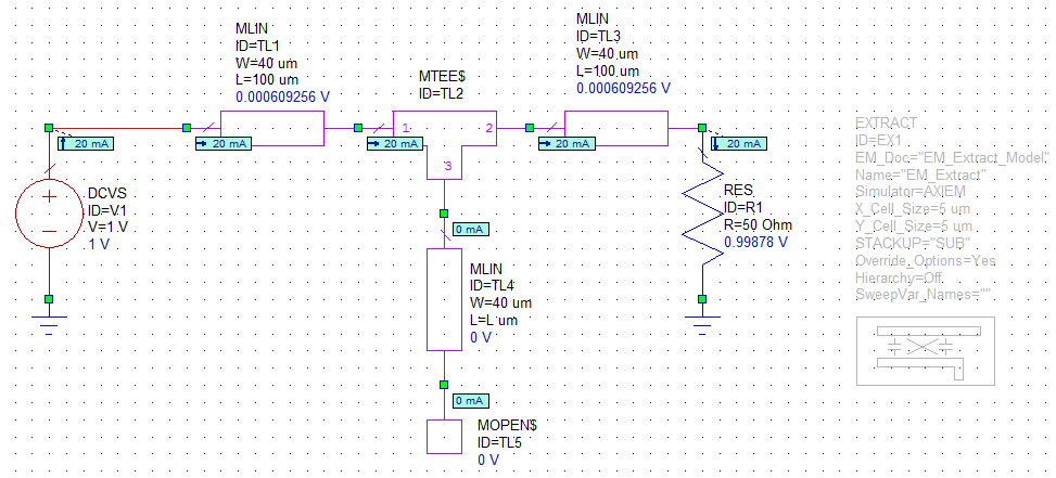
Ohm's law is destroyed? [Annotation very strange, DC leads AXIEM Extraction of MWO... any advise?]
As I was doing my design of the LNA extraction, I get weird results of my DC annotations on the currents and voltages.
To check, I used a simple example (source 1V, less and 50 ohms) and even very weird results which destroyed the Ohm's law.
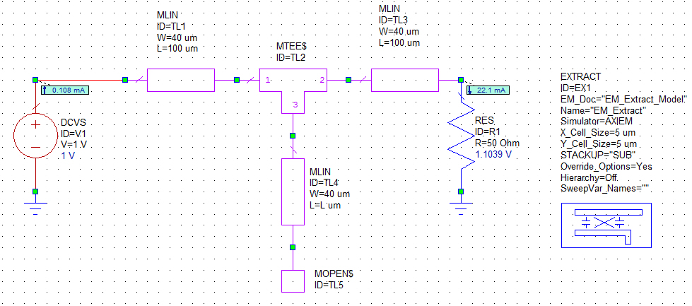
Case 1: No block extraction. Normal DC correct response.
Case 2: Same circuit as above EXTRACT block activated in AXIEM. 1V supply current is weird to 0.108mA only, while the voltage to the RES is greater than the voltage source. No explanation on that?
Any advise? Here is the file eml MWO
Hello
I noticed that your block of extraction has set up 40 to 60 GHz frequency. But you calculate your annotation current and voltage DC (0 GHz), causes the Simulator to extrapolate all the way to DC to get you a result, which is not a good idea. So if you add a 0 GHz to the list of frequencies that you have in the block of the extract, the result should look like end.
Kind regards
Ideas
-
How draw you stability circles in MWO?
How draw you stability circles in MWO inside the smith abacus?
just found... CSRI
-
Implementation of Stackup for heatsinks with cavity in MWO
I have a card Board 2 layer FR4 based on a heat sink.
The metal top of the page and the metal bottom of the FR4 substrate have traces of RF with vias connecting them. Since there are structures of RF and vias to the bottom layer, to avoid it being shorted with the heat sink aluminum, then you must put a cavity of 1 mm on the radiator.
the installation would be as below;
Open the top cover
high metal
FR4 substrate
metal background (GND with RF lines)
heatsink (with cavities)
Open the bottom coverPlease see presentation here;
http://ImageShack.us/photo/my-images/259/cavity.jpg/
Question is how configure you the envelope or for this stackup in MWO?
Hey boom,.
The trick is to think of the throat as cut in aluminium by layer. Here's how to set your envelope:
In "material Defs." tab, include aluminum as a conductor
In 'Dielectric layers ':
1 air (thickness x FR4 maybe 5)
2 FR4
3 air (thicker that the depth of the Groove you plough in the heat sink)
Upper limit: about open; Background limit: aluminium
In "Materials", add an entry for aluminum, any thickness.
In the layout, draw a "Via" with "extended" from the 1 on the dielectric layer 3 using aluminum material. The shapes you draw defines the coverage of the area where the Groove is not present. You can also copy these forms, change their material to what is on the bottom of your Board (not like the "Via") and you cover them existing. For an example, see the attachment.
I did a "quick and dirty" job on it, exactly as if you were only using AXIEM. If you also use MWO for presentation and general circuit design and want to be able to use these layers there as well, then you must add the necessary drawing layers and map for EM for extraction.
If this answers your question, please identify yourself as a solution.
-
Optimize on the harmonics to the measured power of P1dB
How to optimize the harmonics to the measured power of P1dB? Currently, I am doing this with lots of equations but is there a direct way to implement?
XDB element to measure the power for example the 2nd harmonic by the parameter FUNC_OUT to P ("2f1") and an optimization of the configuration for this goal.
-
My data file trace the wrong frequencies in MWO
I'm plotting a S parameter file, but frequencies in my chart do not match the frequencies in my file.
Sometimes when you try to plot data files (let's say the measured data) against the results of simulation, you get unexpected results. This coming do not select the right frequencies to the extent.
When you add a measure to a graph there is a selection of default frequency, but you can replace it. The extent of dialogue for this field is inside, as shown here:

by pressing on the ' > ' to the right of the Freq Sweep field, you can see that there are two selections of possible frequency for the file for the data file.
- Document is a list of the frequencies in the actual data file
- Project is the list of frequencies in the frequency list of the projects and those who most probably used by your schema.
If you try to plot two different measures against each other, you'll want to make sure that you have defined two measures on the same bandwidth.
Another thing to watch if you are using a data file with a small number of frequency inside points is the interpolation method. We have a knowledge base article that explains how to select an interpolation method and the trade-offs.
-
How to make a perfect switch in MWO?
I want to switch mode AMP 'current mode class D', at the first, I want to check AMP ideal State.
So, I use Ideal switch in the ADS. But how can I make an ideal switch in CWA at the circuit level.
The best way to proceed is to use the Switch_AP element which is a perfect switch. This element will work only in the APLAC Simulator so you can choose this simulator when you create your measurements. You need to set some parameters of the switch to work in secondary harmonic balance and you can see a concrete example of this joint.
-
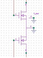
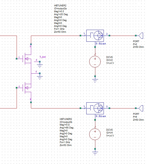
I have a 2 transistor die in a single package as shown below
I have 2 questions:
1. How do you Load Pull in MWO under a constant output power? I am using the CONSTPOUT in MWO but do not know if it works. I plan just to do this on a transistor die single step and only ground the other transistor.
2. is it possible to achieve the loadpull using 2 simultaneous Tuners to the output using standard variables in the MAG and ANG for both tuners, or is it possible to have two tuners to support with the same ID?
See 1 above: are you sure of your amplifier may reach the level of output power wished all termination impedances in the sweep of loadpull?
-
University students should use the forum OR support questions, https://decibel.ni.com/content/docs/DOC-26731
Customers who pay should see the AWR site for directions on how to get support on AWR products. http://www.awrcorp.com/AWR-support
This includes support on:
Microwave (MWO)
Visual System Simulator (VSS)
Office of the analog (AO)
AXIEM
Analyst
AntSyn
TxLine
Fix
-
Hi all, I wanted to perform the characterization of the PA. I used the example of characterization of field-effect transistor in the CWA, but I replaced the model amplifier with Rf3833. I get an error message in the status window saying "the branch labeled already in the output with the different nodes (S\RF3833. X1@C. NP found more than once) ". I was wondering what exactly this means and how to fix?
See you soon
Hello
It was a little difficult, but there is a solution. In the future, please let us know what version of MWO you were using when you found the error.
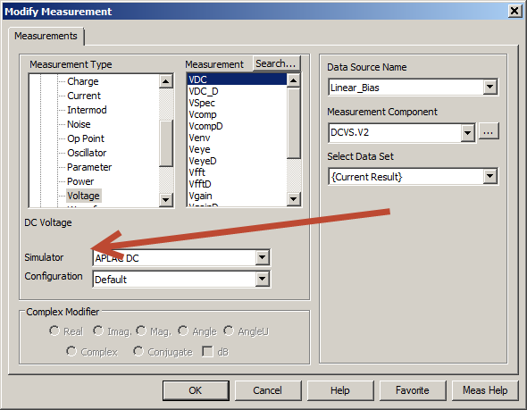
The problem is that this model will only simulate in the simulator of Aplac and some of the measures in this project use the default linear Simulator. You can go to any extent, double click, and there is a "Simulator" drop-down box.
If you change all of these "Aplac" you'll be fine.
Note, there is a script that can help from "Scripts > Simulation > Convert_Meas_to_Aplac" and it will convert for you.
Note 2: This model RFMD is only 32 bits and only works in v11 or earlier. V12 has much faster speed of linear simulation to Aplac, so you should ask the provider to update their models in support of 64-bit AWR. This feedback is much better when it comes to their customers of AWR.
Thank you
Support of the AWR
-
Hi, I have a conception of circuits (EM structure for use with AXIEM) I want to modify for use with a different dielectric. As a starting point, I want to resize the design evenly. Is this possible with the MWO layout editor? There are a lot of beautiful operations available then maybe there is an obvious way to do it, but I have not found an easy way to just model balance in both directions (or one) by a factor. Ideally I could resize the whole design without having to scale-so-realign each polygon regardless.
Thank you!
You can stagger the work cells. So the trick is to save your design as a work cell, place it in a new structure and a scale to the need and then flatten it if you want to do more editing.
- Select what you want to change in the layout.
- On the menu: Layout > Celll GDSII do...
- Specify a library name and a cell name to the collection of shapes that you selected.
- Create a new structure, or copy one you had and remove the stuff you want to scale, and replace.
- Click on the tab page layout (or view > Layout Manager)
- Click the page layout objects pane to open it, then click the cell library, you have created (not the cell inside).
- The component layout of the cells should show your cell: drag in the structure of the EM and it lay.
- Right click on the cell in the layout > Shape Properties, set the scale as you want, and then click OK.
- Right click on the cell again > cell flatten. And then click OK. The default values should be fine.
Sorry I don't have time to hang on and paste images. Let me know if you need it.
-
Hello
I'M NEW ON AWR MICROWAVE OFFICE.
I TRIED TO LEARN AXIEM EXTRACTION AND TRIED ONE OF THE CIRCUITS.
AT THE END I END UP WITH ERROR
"MY HEEL - Extraction.
12:52:37 EXTRACTED. EX1: "AXIEM AWR - Async" function is not supported
Simulation - LIN: MY HEEL of. $FDOC
' 12: 52:37 Extraction failed.THIS MEANS THAT ON MY LICENSE I'M NOT ALLOWS TO AXIEM SIMULATION? AND NEED TO UPGRADE FOR THIS FEATURE?
Thank you
HI Fadi,
Yep, the functionality of the MWO-125 does not include the AXIEM, which would explain what is happening. On the block of the SNIPPET, you can change the simulator at EMSight and you can get an idea of AXIEM but EMSight much restricted that AXIEM is not, as the requirements of the grid (mesh grid, not your forms), ports must touch the envelope, you must know how to space out the sidewalls geoemtry, etc.. I would say AXIEM is 10 to 100 x easier than EMSight when using extraction. You can contact your local sales representative and ask for an assessment of the AXIEM.
Support of the CWA.
-
Page layout in V11 license problem
Hello
I got a support request on an error with page layout in V11 license. The same project works very well in V10, but while trying to open in V11 layout options only are not enabled (attached screenshot). They have the MWO-449. Can someone tell me what the problem is here?
Thank you!
Hey Jake,
Did you put your license file in the installation directory or elsewhere?
You can if you put it in the installation directory:
1. move the license out of the installation file
2. open the software. It will put you in the configuration dialog of the licences where you can press set location.
3 browser to the new license file location and select the license.
4 restart the design environment and see if the problem is corrected.
Thank you
Shane C
-
Import the SPICE model for transistor BJT BFP720F in Multisim
Hello
I'm trying to get the SPICE model for the BFP720F transistor provided by Infineon to work in Multisim.
I have attached the template as provided by the manufacturer.
If I import it as-is, I get error messages "invalid node identifier '<4>'" (I have translated that German, it might not be exactly this message in the English version).
So I tried to replace all the "<4>" with "4", which seems to help, but now the error is "adjusted temperature setting"VJC (PC)"negative" and "incorrect use of the parameters of the model. Now I don't really know what to do with it.
Is the template provided in the wrong format? I somehow can it in the right so I am able to use it?
Because I need for my project semester in College, any help would be much appreciated.
Thanks in advance!
Hi NikoNR,
When writing a detailed description of what I did exactly with the Wizard component, the component again to create in Multisim from scratch, I found that there are different SPICE models provided in the package for use with AWR MWO. They have a different file extension, but are normal text SPICE inside files.
It turns out that they actually work with Multisim. The difference is small, there is only one temperature (TNOM) setting that is absent in these models, distinct from the "general" I first tried to use. It seems that Multisim had a problem with this setting, leading to the error I encountered.
Anyway, the problem is solved now. Thanks for your help

Good day
(The now much happier) EE-student
----
Edit: I have attached the SPICE model, that I ended up using, in case someone at - he never met a similar problem. The only change I did this, is to replace '<4>' with '4' in the part of the diode (single occurrence here). I had to zip to download with his original extention (.mdl).
Maybe you are looking for
-
Elitepad 1000: navigation & new installation 8.1 (after 3FO HDD) Win
Is there a way to navigate through the screen of windows once you start USB? I tried to use Elitepad USB adapt, but the mouse does not work, although it works perfectly under the BIOS menu. If it be that this adapter uses usb 3.0? But even once, I tr
-
Message Notification has stopped working on the upgrade of Maverick
New Message of Notification stopped working since I upgraded in Maverick. Help, please...
-
Hello I think with the purchase of a 15-D045NR. The problem is that I can't find out if the RAM is expandable on this computer. It comes with 4 GB of Ram, but did not mention if it is expandable. I already bought a 15-d037dx, but I'll take it in the
-
Generic Host Process for Win32 Services has encountered a problem and needs to close
I have Windows XP Home Edition, version 2002, service pack 3 The link to "Windows Updates" on the microsoft website does not.
-
New Microsoft Office 2007 update FAILS
Try to reload the new Office 2007 SP2 update. FAILS every time new codes of Defender loads, but no new SP2. I see 2 file sizes. one of 247 MB and the other 290 MB. All other updates work fine. I'm running Vista 64 Ultimate. Tried all the thing