LVDT
Hello world
I would like to know if it is possible to acquire data of Solartron LVDT using two data acquisition systems:
-6036E DAQ (used with Labview 7.1 and traditional DAQ) map
- NEITHER cDAQ-9174 and NI DAQ 9207 (using Labview 2010 with DAQmx).
If no, what type of instrumentation OR do I need?
Thanks for the replies.
matomato
A link diredt sheet would have been nice, but google has been helpful...
According to this data sheet , the sensor you already outputs 280mV/V/mm when they are under 10V DC.
So what you need is a 10mA 10V power supply connected to the red/blue and you can connect the output (white/green) to your analog input to your 9207
The output being ratiometric to the supply voltage, it is advisable to monitor this tension too.
Configure both channels in differential mode.
If you do not have a 10V power supply, you can do a first test with a 9V battery, but with a current consumption of 10 MA that he won't last very long.
Tags: NI Hardware
Similar Questions
-
scale and LVDT position sensor
Dear comrades:
Hi there;
So, first thing, you should think everything is the conditioning of signals, you will need. The myRIO is an awesome tool, but does not include the conditioning of signals. . You need to load voltage cell and you'll read a resistance value, we must build a wheatstone bridge to do this. Take a look at the following link; Gauges
Regarding the LVDT. they operate on the principle of a transformer and consist of a set of stationary coil and a mobile core. An LVDT measure moving by associating a signal value specific for any given position of the kernel. LVDT signal conditioners generate a sine wave of the main output signal and synchronously to demodulate the secondary output signal. The demodulated output is passed through a low pass filter to eliminate high-frequency ripple. The result is a voltage proportional to the displacement of the base. The sign of the DC voltage indicates if the move is to the left or to the right.
You can enjoy the FPGA chip in your myRIO and use this example
Finally, to save the data to excel, you have several ways to do so; the easiest way is to use the Express VI report, or you can use scripture to table VI.
Hope this info helps
Greetings
-
Measurment LVDT DC with CompactDAQ
Hello
I am currently working with reading as a result of an LVDT for a project that the present model is the DC LVDT Omega LD620-25
According to the data sheet's model requires a voltage of 10-30 v and a maximum current of 25ma
http://www.Omega.com/pptst/LD620.html
with regard to the available data acquisition modules: the NI 9237 and the 9220 OR by using a module compactDAQ
as the NI9237 has an internal output of 150mW obtained maximum current is 15ma, simply use?
the 9220 OR will be used for the acquisition of data but provides no port of excitement!
as for the solution another I thought using an AC adapter / CC of normal 12Vdc 100ma with a variable pot or a circuit voltage divider to provide the necessary tension
but I have several concerns with respect to the Earth circuit. in this system, I will have two independent reasons!
What will be the best solution to connect the LVDT module to the 9220 OR and provide a source of external excitation?
Thank you
Hello ghattas.ak
Consider the NI 9218. It can provide 12V exictation to ~ 50 mA per channel and read 5 or output 10V DC LVDT. To use this excitement 12V, 9 - 30V power supply must be connected at the Vsup pins. As you said, you can also use the 9220 OR with external excitation. The NI 9237 measuring range of +/-25 mV/V does not cover the 5 or 10 v output sensor you.
See you soon,.
Izzy O.
Product Support Engineer
National Instruments
NI.com/support
-
differentiate the end simple connection lvdt data Dynamics usb6008
Hello forums OR
I use an lvdt to measure the movement of the damper using usb6008 and voltage data of channel CSR given Dynamics me gives the information of displacemt against time and I want to convert this speed so that I can have the speed of compression damper.
Please replace the graph with a graph (and the increase in the number of samples), run it once and make a "current default values edit_make", save the vi with the data and post it.
Because of the noise the drift looks even more noisy (a multiplication with 2 * Pi * f in the frequency domain), Solver of problems: filter

here I posted a filter Savitzky-Golay, who do both: filter the signal and derivatives (like a quick shot: try 20 sidepoints, order 3, 1 diff)
Information important limit (condition): frequency range you want to cover?
-
Hi all!
I have a HBM (LVDT) inductive position transducer. WA series. I need a PCI card to read this sensor. I took a quick glance at this link http://zone.ni.com/devzone/cda/tut/p/id/3638 , but I'm looking for a simpler solution in the form of a pci card.
Any suggestions?
All the best.
Gabriel Oliveira (Novo Hamburgo / BRA)
Hi Gabriel,
Doesn´t OR have a card PCI-conditioned to acquire signals LVDT, you will need conditioning of signals or you can both a system NI SCXI to acquire the signal of an LVDT.
You can try to speak with one of our technical sales representative.
National Instruments Brazil
(55-11) 3149-3149
Kind regards
Abel
OR Brazil
-
LVDT offset before running the program
Hi all
I use an LVDT to measure the movement of the ground. This must take into account both the consolidation and swelling and therefore requires the LVDT to move in both directions. As a result, the voltage must be reset after the LVDT is pushed so that it can record both negative and positive direction. So far I managed to do it using a business structure that runs when the "zero" button is pressed. However, it comes into force once the program is run. What I need is a button "zero out" which can be used before the program is executed. I want so push in the lvdt, click on the "zero" button, then start running the program to avoid these initial tensions is recorded on the xy graph.
I found a vi file that does this, but it was very complicated and used old version of labview. I'm relatively new to labview and therefore could not follow the coding on it.
I've attached the vi file to make it easier to understand. Your help is greatly appreciated
See you soon,.
Gurung
Two screen grabs show how I did the same 'Auto zéro' function when you use an LVDT to measure displacement, I was also saving strength at the same time then graphically representing the post record results.
On the first race the true / false loop is set to TRUE, in this case the displacement is subtracted from zero to provide compensation, this offset value is then passed to the shift register where it remains as a constant for subsequent itterations of the main loop, while the value is simply passed straight through the true / false loop with nothing done to it on all iterations after the first.
The offset value is then added to the data read from the LVDT to provide a number of displacement from zero since all that the program was headed all first. There is a 'Save' button on front of who's in a hurry to start and stop recording data - hope this is a help - Mike
-
How to connect an lvdt and cell to usb 6008
Please help me iam do not know how to choose a daq card. looking for a lost lt but iam.
I want to measure the force and displacement at the same time a bench test of suspension and I wanted to use or usb6008 because of my budget for the project.
can I use this daq card to measure these parameters?
answer please... Thanks in advance.
Hi Sylvia,.
To be able to determine or not with a box NI USB-6008 would be appropriate for your application, it would be useful to get a little more information on measures you can take. If possible you would be able to provide the range of voltage, you intend to measure with your instruments and sampling rate, you need?
I also noticed in the subject line you use an LVDT, will you also production for this tension with the 6008 or this will be done separately?
To give you some setting in context, the NI USB-6008 case does not really simultaneous readings at every moment, but will be replacing rapdily between channels, to give effectively simultaneous samples. As this unit has a sampling rate of 10 kech. / s, and you use 2 channels, the sampling rate effective for each entry would be 5 kech. / s.
-
You can use NI 9237 for the LVDT readings
Dear comrades,
I wonder if I can use NI 9237 and NI 9945 to get the reading of an LVDT. The interest is to measure the movement using Solartron DC Miniature LVDT.
In our laboratory, we have NI 9237 and NI 9945 and I would get your advisor if it would be good enough to measure the movement of an LVDT.
Thanks in advance.
Hi Gtharm,
For the Solartron DC Minitature LVDT transducer already includes oscillator, demodulator and filter which alow the sensor to accept the input voltage and provide a DC output from the position. Therefore, instead of using the bridge according to the measure such as the NI 9237 or NI9945 modules, you must only input I take the input voltage.
The LVDT voltage range would determine which modules HAVE you need to take the measure. Of the specification, you need to at most 100 Hz to get the signal from the probe safely.
I hope that this help mate.
-
Acquisition continues two sensors LVDT
I'm trying to build a program to monitor the two LVDT sensors inside a table of machining to measure vibrations. I wish I could acquire as close as possible continuous. I'm looking for small delays because the plan is to have a feedback mechanism later and this would require very fast reaction.
I have some experience with labview but am quite new to the use of the structures of the queue. I have done wrong data in a type that I can work with. How can remove my waveform data and use it to perform calculations on the frequency and amplitude?
And by the way, I implement the queue correctly? or does anyone have recommendations to my disposal vi and architecture?
Thank you very much for your help.
I'm using labview 8, but I have access on other computers to labview 9.
-Arthur J.
In the original VI you posted you do not do anything with the data in the queue. You preview the queue and then nothing connect to the wire.
1. use Dequeue. This removes the oldest element from the queue and makes it available. Overview examines the data without deleting the queue.
2 do something with the data. I looks like you can split the four-channel LVDT and places the data in the shift registers. Do you need to initialize the shift registers or do you want that perform the data from the old stored and used in the next series? It is usually best to initialize arrays to the maximum size that you want, and then use replace element of array located inside the loop. This avoids the reallocation of memory.
3. review the appropriate data structure. You start by buying a table of waveforms. After the filter, you have dynamic data. You use in the loop of another tables 1 d of doubles. If you haven't since the waveforms calendar information, try to get data from the reading of data acquisition in a table of double and stay with this type of data overall.
4. consider to put the filter in the lower loop. Usually a producer/consumer that architecture acquired only data in the loop producer and all analyses in the loop of the consumer.
5. as someone pointed out before you need not the structure of the sequence. Data flow will take care of that. You must connect the terminal nodes Visible property error loops below to apply the desired sequence. Use a control with a blank label is OK, but if you have two of them how do you know which is set Visible? It is better to give each control and seeing a unique label. If you don't want the user to see the label, check the invisible label or use a legend or both.
Lynn
-
Hello, I am very new to Labview (three weeks) can someone give me a few examples on how to measure for LVDT position vs time? It is very simple using an Oscilloscope of cursors of X 1 and X 2 of position to measure delta time, but I don't know how to do this with LabVIEW or charts graphs. I want time to measure the trigger at the fist sign of movement, total race time and dredging (to cylinder). I have attached a picture of what I want to measure. Are there specific screws to search for these times. Even by manually placing cursors on the desired position in labview, all I get is the time for each cursor but not the time delta between cursors.
Any help will be greatly appreciated
Juan
-
Assistant OR-9234/Sound and Vibration: being reset to zero (crazy) automatically input signals
Hi all
I have a voltage source and a force as entries in a sensor module DAQ 9234.
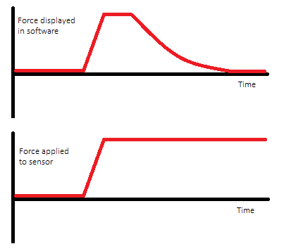
The software focuses both signals whenever they change. For example, if the voltage is read by data acquisition increases up to a constant value, the software will trace an increase in tension, followed by a slow return to zero. Similarly, if I increase the force applied to the force sensor and keep it at a constant value, the program will draw an increase in force, followed by a return to zero.
Here is a graphical representation of the problem, which uses the sensor force for example:
The sensors are passive. The sensor is a PCB 02 208, and the source of tension comes from a LDM-1000 signal conditioner, which receives a signal from a MHR 250 LVDT. By the LVDT core displacement changes are interpreted by the signal conditioner, which translates as the measure of a voltage value that can be read by data acquisition.
Thank you in advance.
I assume you have the rule 9234 on coupling AC mode, while you should use DC coupling.
-AK2DM
-
Problem with the sensor of pressure and NI 9205 with NI 9263
I have a bridge pressure sensor based with a range of 0 - 5000 psi and requires a 10 V excitation. The output is 3 mV/V. I plugged on a cDAQ with a NI 9263 providing excitement V 10 and a NI 9205 to read the output values. I would expect a 0-30 mV output corresponding to 0 - 5000 psi, correct? (Incidentally, the NI 9205 module must be accurate to 0,1 mV or this should lead to a precision of about 16 psi, right?).
However, when I tested it in fact the sensor on the run a test ranging from 0 to 1000 and back to 0 lb/po2 (now for quite awhile to States of pressure) the values I get from the NI 9205 are about 204.614 mV for 0 lb/po2 and then goes 204.867 mV to 1000 lb/po2 (actual results are noisy (, so these are averages). I enclose the SignalExpress file used for the test as well as the Excel file containing the resutls. Testing was performed with a number of other active sensors (load and displacement, LVDT and gagues strain gauges) in addition to the pressure that I'll eventually use them for my experience. In the SignalExpress file, the pressure transducer is the only sensor receives the excitement of the NI 9263 (ao_0) and ai_3 on the NI 9205 module.
So this time I tried to run the test again, but changed the SignalExpress file (second .seproj attached) to include only the pressure transducer. But now I don't have an answer at all by the transducer (it remained simply flat).
As to the connection of the transducer material, it is a connection 4-wire (excitement, - Exciation + Signal - Signal). I plugged the cables from signal to pins 4 and 23 (AI3 and AI11) for a differential pair. Then, I plugged the son of excitement to the pins 0 and 1 (AO0 and COM). Finally, I took a wire jumper and connected 23 on the NI 9205 module PIN to pin 1 on the NI 9263. I made this last step at the suggestion of support OR for a previous problem with a string potentiometer. This stage connected the ground between the two modules (the sensor did not answer with a pressure change when I don't have the wire).
I appreciate any help as to why. I did not receive a 0-30 exit mV.
his does not work like that.
The probe should @30mA to 10VDC. There is only available from the canal AO 9263 1mA. you need another power supply.
-
SCXI 1180 not detected and not ListBox!
Hello
I have a SCXI1001 chassis, with gauges bridge modules, modules thermocouple conditioner, lvdt modules and modules input voltage. I used it for a long time, but in fact, updated never need to use the raw tension module input (1180 and accessory).
Today is the day that I need to acquire temperature and voltage, but... I can't configure the scxi chassis!
Voltage input module is in slot 4, and when automatic detection detects not. But also, if I try to put it manually, i.e. open the list box and select it. It will not appear in the drop-down list.
How to configure the 1180 module?
Thank you in advance.
Hi user,.
Like her, he said in the document referenced by Ajmal, '[...] For unused connections you access via the SCXI-1180 module, you can reference them exactly as if they were the usual channels of data acquisition. "Therefore, you should check your stitching of data acquisition card in order to verify what pins are related to the physical channel you use.
You can verify that you are the pinout by clicking Start > programs > National Instruments > NI DAQ > NI DAQmx help and then navigate using NOR-DAQmx Device terminals > DAQ hardware.
I hope this helps!
-
1-point mode data record continues
Hey guys, I want to put an LVDT tension on a timed program. I would like for this value to be saved ONCE whenever it hits my case of busy time. I am making 3 to 4 for each instance values, when even the loop is one iteration 1 time. I know I'm sampling well above 1... but I can't seem to understand how to put this value in the data file only 1 time. I have all my configuration case yet, I was testing with '2' seconds.
-
Hello
I'm trying to delvelop software (Labview) that is installed on the student laptops (12-20 max) who reads data continusly (max 1 to 10 hz) of the computer laptop instructors. It tells me that the use of a text file and have the students to read continuously is not a viable option. Any help would be greatly appreiciated. I write mostly programs data type simple aquistion strain of measurers LVDT etc. as an engineer. I'm not a full time programmer, so I'm learning as necessary. The data is constantly simple double prescision updated of a simulation.
This will be a freebie for schools software later. Help, please... Thank you
Well, you can also use TCP instead of UDP. The TCP network protocol provides a bit more load to ensure that packets arrive in order and will be sent if missed. That does not necessarily all the data arrive. Disconnect a cable network for a short period of time, and a sent packet eventually timeout and exit. But the internet tracks on this Protocol good enough, (at least that's what I said
 ) so I'm sure that it will work reliably enough for your small network application.
If you need other insurance, all your data arrives, so you can serialize each data package yourself, put a sequential number in communication with other data. If the receiving program detects a missing number or one out of order, then at least you know your application level and can do something. But I seriously doubt that your application is so critical that you need to worry about the implementation of this. Just rely on TCP and you'll be fine.
Maybe you are looking for
-
How to buy a magsafe 2 replacement duckhead
I can't find how to order a duckhead replacement for a Magsafe 85 2 watt PSU. American 120-Volt version.
-
How can I delete the Gmail Manager add-on?
The "Gmail Manager Login" box keeps apearing and request password for my accounts in Yahoo. I type the password, but the login box still appears. I want to delete this add-on. This has happened Each time Firefox opened is maybe two weeks
-
Hi all I have a Pavilion dv6810us dv6700 with a broken motherboard line. I'm looking to replace it, but am not sure exactly what part number I need. The sound that I found is 459565-001 and 443774-001, but I am unable to find the exact specifications
-
ArcSoft Scan-n-Stich is available for MAC?
I think that Best Buy sold me a scanner that I can't use - I'm a graphic designer and try to 'sting' 2 images does NOT work!
-
Adjust the size of the font of the label of the icon on the desktop in Windows 7?
Adjust the size of the font of the label of the icon on the desktop in Windows 7?