measure 4-wire RTD
Any module can do 4-wire RTD measurement with resistance heat about 10 to 20 k ohms, total 20 channels, thank you.
Hi Alex,
Yes, it would work.
Yik
Tags: NI Software
Similar Questions
-
I suspect I already know the answer to this question:
I have an PXI-6224 M-series data acquisition card and a terminal of the SCB-68 block and want to take action using a bunch of 4-wire RTD. Is the power to the power source for these measures 6224, or is - not possible with the hardware I have?
I know that NEITHER you propose other solutions to my problem: I am interested to know if I can do these measures with the device that I currently have on site.
Thank you!
Hello Jeffrey,.
You have two options here, but it doesn't look like you need some hardware.
The SMU-4357 built conditioning of signals, but it will not work on the chassis curent you have:
http://sine.NI.com/NIPs/CDs/view/p/lang/en/NID/210596/
We also have an option with the NI 9217 cDAQ, but once, it gets you into a different platform:
http://sine.NI.com/NIPs/CDs/view/p/lang/en/NID/208804
We used to have an option that we sell no more - the SC-2042RTD. If you are lucky and have one of them on hand so here's some info:
http://digital.NI.com/public.nsf/allkb/4FF2C0F8D11B99B486256F4C006DCEA0
You can also use these two elements in conjunction with eachother with your current PXI card:
http://sine.NI.com/NIPs/CDs/view/p/lang/en/NID/12311
http://sine.NI.com/NIPs/CDs/view/p/lang/en/NID/10778
Finally, you could get an SCXI chassis and drop them in:
http://sine.NI.com/NIPs/CDs/view/p/lang/en/NID/201609
Thank you
Joel C
Technical sales engineer
National Instruments
-
NI9217 + CompactRio to measure two sons RTD resistance thermometer
I have 4 two sons PT1000 RTD. How can I use NI9217 with the cRio-9024 to measure the temperature?
I followed the link below, but I do not know where to put the module in mode 3-wire. Right now I'm getting + -1200 C, which must be wrong. And RTD0-3 are now available, but I need to use all of the 12 stations to measure RTD 4. I would appreciate any idea and help. Thank you in advance. I have attached two screenshots, which displays the property page for NI9217, and only 4 devices can be used in each NI9217.
http://digital.NI.com/public.nsf/allkb/09E99F60C481D613862572C300637341
Well, the unit has a range of 0-400 Ohms (she waits a RTD 100ohm) so throw a PT1000 in the system certainly will give him a max value output throughout the day temperature.
-
How to connect RTD (method 4 son) using a 4 x 16 (2-wire) or 2 x 32 (1-wire) switch topology
Is there a way to switch cables of 4 measures using the PXI-2530 with TB 2631 module, which has only 4 x 32 (1-wire) and 4 x 16 (2-wire) topology.
Hello!
The TB-2631 attached to a PXI-2530 module will let you assume a 4 x 32 (1-wire) or 4 x 16 matrix (2-wire). Connection to a DMM with a topology 4 x 32 1-wire you would be able to connect the DMM to the 4 lines and up to 8 4-wire RTD to different columns (32/4 = 8). You should consider CT 2630 if 8 isn't enough; This terminal allows you to assume a topology 4 son 32 x 1, so you could measure up to 32 RTD of the DMM even with this card to a single switch. Let me know if what I said was not clear.
-
Ethernet affecting measurements on compactRio stand-alone
Hi all
I have CompactRio cRio-9024 with Modules 9205 and 9217. CompactRio runs independently, without connection to a PC.
I have a RTD resistance thermometer, it's a PT1000 2 son. 9217 does not support 2-wire RTD, so I use 9217 as a current source and use jumpers to NI9205 to measure the voltage on the cables, so calculate the resistance of the sensor. (Resistance = voltage 9205 / constant current of 1mA 9217)
In addition to the RTD, I have also other devices connected to NI9205, what differential voltage is recorded measurred. Everything works well before PT1000 is connected.
The problem is, somehow the Ethernet affects all measures on the NI 9205 module. When Ethernet is connected to the PC (PC does not need to be turned on, simply connected), everything would work fine. When Ethernet is not connected, all the tension would be down and even go to negatives. I don't understand how it could be possible, that Ethernet could affect the system.
Any ideas? Maybe there is another way to measure the 2 wires PT1000 or how could remove the Bug of Ethernet?
Thank you all in advance!
Best regards
iamnewhere
I would check for a ground problem. Sounds like your ethernet cable will carry a field, which isn't good. The cRIO otherwise is somehow?
-
With the help of RTD in PCI-6259
Hello
I'm trying to measure temperature using a 3 wires RTD and a 6259E PCI data acquisition card. All examples and tutorials that I found were the RTD module or not use regular data acquisition. Is there a way to connect to the RTD in a regular data collection? Any help would be greatly appreciated.
Thank you
Vijay
vjkumar,
Measure the RTD with an ordinary DAQ card going to be like a voltage measurement. From there we will put voltage to the useful units nationally. What part of the process you are having trouble with? You are programming in LabVIEW? What terminal blocks do you have?
This is a great home page for all things related to DAQmx.
-
CQI RTD sample.vi with simulation device
Hi all
I am student on samples DAQ in labview 2009, I have no DAQ hardware, but I faked 9188 NI and NI 9214 (thermocouple). I want to run 'acq RDT sample.vi' devices with these simulated, but when I run the program it displays error "possible reasons: device to which is attached the sensor doesn't have a source of available internal excitement." Select another device with a source of available internal excitation or provide external excitement. ». However, in the web, it is said that NEITHER 9188 and NI 9214 are available for real-time measurements. What is the problem with that?
What Jacob said, is that the 9214 is not designed to work with the RTD sensors. An RTD is a resistance that changes the value with temperature. A thermocouple produces a voltage proportional to the difference in temperature between the junctions. A measurement system for thermocouples need measure the voltage and often compensates for cold junction temperature. A measurement system for RTD must measure the resistance which is generally to provide a current, and then measure the voltage drop. The 9214 is not a supply for RTD current circuit.
The specificatioons for the 9214, it seems that it will work with the real time operating system.
Lynn
-
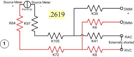
I have a problem with a PXI-2530 switch card work in matrix mode 4 X 32. I need to determine the resistance of the pairs of specific relay within the matrix. I have a PXI-4130 and a PXI-4071 in the same chassis, so I take measures 4-wire in a configuration like this...
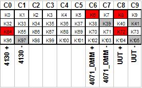
Resistance symbols represent relays in the switch. Here is a representation of matrix-style switch routes I use. (This should look more like the interface of soft face before switch)
The two diagrams represent so how I take my measure. I shorted outwardly columns C8 & C9 (shown in the first graph), I am sourcing 500 microamps of current and toggling the current source for a positive and a negative measure, I am able the voltage with the DMM. For the above measure I'm mesure.2619 ohms. This should be of course my resistance of the relay K8, K41, as well as Terminal block and wiring.
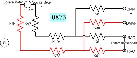
Here's another schema. This should measure the resistance of two same...
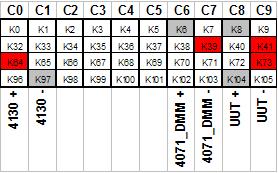
All I have changed is routing between the meter from the source. Here's the view from the matrix...
With this measure I'm mesure.0873 ohms. I can have the same resistance as the first example except getting a very different measure.
It gets even more interesting. If I had to take 4 pairs of wires, I use here, there are 16 possible configurations. I took each of these measures, and half of them gave me environ.25 ohms while the other half gave me environ.09 ohms. I tried this on a 2nd chassis and got the same result. My data are in the attached sheet. (My examples above are rows 1 & 5.)
Taking the measure of how we are, all these measures should be substantially the same. I have a current source constant, (I even tried a crimp in instead of the 4130 and got the same result.) and the meter is high impedance. If I had a pattern for the PXI-2530, I could do a little more analysis to know why I get various measures. Is there some diodes clamp on the lines or columns in the matrix? Something external must act solange this circuit. If I can find out what that is, I could determine my resistance to relay to a quantifiable level of uncertainty.
Any help would be greatly appreciated.
Greg
It seems that I can't remove. The correct message was placed here...
Once again, my apologies for the incorrect positioning of the post.
-
Question tab User Interface control
Heey everybody,
I have disigned a program and user interface, on this user interface, there is a tab (see attachment) control in this tab control, you can select several measures. It is a school project and according to my professor is not clear enough what measure is selected.
My question: is there a way to give the active tab a different color? If you know a way to create a nice user interface that has the same capabilities as the control tab (select measure and wire in measured values).
Thank you
Hi Grasman,
It is possible to give different tabs of different colors, first of all, you must enable several colors - "just right-click on a tab on the control. "Select Advanced" allow multiple colors.
To change only the color of the active tab, please see Steve birds VI, you can find it on the following forum post
Kind regards
Tobias
-
Thermistor FP-1001, FP-RTD-122, 3-wire
Hello
I have FP-1001, FP-RTD-122, both connected between them and cable 3-wire thermistor on it (3,4,20 entries, properly)
I want to measure the temperature. I have RS232-RS485 converter. Using the VISA test Panel, send something to port makes the FP-1001 to NETWORK light blink.
Opened DQA in LabVew... going to 'acquire signals-Analog-> temperature >' and everybody that I look for, says I don't have "no device supported.
If there is a way of: How can I solve this? I make 300% need FP-1000? :\
Hi wattss,.
In aid of filedpoint is simple, but it is not as simple as the use of our more modern devices.
The FP-1001 can be connected directly to a PC with a RS485, as seen in the FP-1001 datasheet here:
http://www.NI.com/PDF/products/us/4dio541_543.PDF
1. you should see the RS-485 port in MAX. We have problems with low series adapters range from time to time, please use OR products, such as the NI USB - 485, they implement support of complete equipment for the serial port.
2 configure the equipment as described in the FP-1000/1001 FieldPoint Quick Start Guide.
3. you will need the drivers FieldPoint .
4. you will need to add the FieldPoint Max: right click and add a "FieldPoint Serial' to the ' my system / devices and Interfaces" by discovering the serial port.
5. you will need to configure the nodes of the thermistor on the FP-RTD-122 (just explore the menus / toolbars / right click on the elements under the FP-1001 node under devices and Interfaces to the MAX).
6 A this point you sohould be able to see the device FeildPoint to the MAX in the 'quarter of data' - this is where you can actually see the FP-1001 data and test if it works.
7. you will need to 'Save' the hardware configuration, you created in the FP-1001 itself: click on 'Save' under 'devices and Interfaces. You must also save the final configuration as a file .iak (from 'data Neighborhood')
Now, you can start to use the FP-1001 of LabVIEW.
For some time I used FP, so you have to get creative with some of the above steps.
Please let me know if you need assistance.
Best Regartds,
Tamas Simon
-
How to measure the temperature of 4 RTD simultaneously?
I'm implementing a systerm requiring several measures the temperature. I am able to make a measure of RTD. But if I have the same code to create two measures of mirror, I get an error - 50103 "the resource specified is reserved". I just started using LabVIEW, so any help is valuable. If there is already material available on this topic, could point me there please.
You can have as many channels of the same type (in this case of analog input) in a task. If your simple solution would be to have four channels in your task. You also need to set your Read DAQmx for multiple channels.
-
Can I use a NOR-9244 for measuring single-phase AC 2-wire 480V?
As the 9244 module is rated for a maximum of 400 v L - N and L - L 800V, to measure 480V, I would need to connect to AI0 AI1 and let the neutral entry floating. Manual outlines all single phase measures referred to the input neutral and has some instructions on the conversion of L - N L - L measures, but it is expressed not bad so I don't know if it tells me that I can directly measure the voltage through AI0 AI1, or not.
Can anyone confirm that I can make measurements with 9244 cable in this configuration, until I drop the $$$ to buy it?
Hello MStewart,
A distinction must be made between Vpk and Vrms.
@GerdW is correct that the input device is ~ 1000Vpk (997.5Vpk). However, this translates into ~352.6 Vrms
The side of 800 Vrms for line (L - L) measures is for multiphase applications.
As you take a single-phase measure, you would use an AIx-neutral (L - N) connection.
The diagram for this is detailed in figure 12 on page 25 of the Manual:
<>http://www.NI.com/PDF/manuals/376131b.PDF >
So to measure above 400Vrms on this unit, you will need to use a power supply external to resign from the tension, as mentioned in the white paper in (specifically the section of voltage):
<>http://www.NI.com/white-paper/8198/en/ >
In summary the 9244 cannot directly measure 480Vrms. You can set before the signal to less than or equal to 400Vrms
I hope this helps to clarify your question!
See you soon,.
-ChristophersonJ
-
Hello
I have a problem with certain measures RTD with the PXI-6289, SC-2345 and SCC-RTD01 setup. I have implemented a DAQmx task in the project, using the following schema:
Name: RTD_Temperatures
HAVE channels 16, 17, 19, 21, 23
RO = 100
PT3851
0 to 250 degrees f.
1mA external excitation
Acquisition mode: 1 sample (on request)
I use a wire 4 PR - 12 RTD of Omega. I've also attached the code what I am about.
My problem is that I don't get the good value of the PXI for RTD temp. I measure the resistance of the probe (109.3 ohms) with a voltage of 0.109V. Using these values, I checked the source of 1mA expected excitement. By raising the resistance of the probe and comparing it to a table of R/T, the temperature should be ~ 75 degrees (who felt all right). However the "temperature", I read of the PXI was 562. I have 5 different channels, and each channel read the same thing when the probe was connected to it. Without a connection to a probe, it was-400 or more. I think it was just due to no connection. I am concerned about the high concentration.
I modeled the code after a thermocouple VI we use already and has proved its worth. Thermocouples connect to the other the 6289 through a SCC68 connector. I thought changing the task to a task of RTD DAQmx would be sufficient. The filter is just a smoothing filter. Any advice or thoughts would be greatly appreciated.
Thank you!
BLUF: When you use the SC2345 and SCC-RTD01, create a new device in MAX under your PXI for the SC2345 and configure the modules you have in each slot of the SC2345. Create a task in MAX (or project), and then select the SC2345 / MOD #: I # (or something similar to that) as the physical read channel.
I finally thought to her last minute yesterday! I have been setting up tasks in MAX under the card/slot DAQmx which had connected SC2345. It seemed logical to me; but my assumption was that the module RTD conditioning the signal and an output value (voltage or what not) to the card and the user just read what is on the card. But I had to in order to operate, the installer places the SC2345 as a new device in MAX under PXI devices. This brought a dialog box configure the SC2345 with the location of the RTD modules. After doing this, when I created a new task, new channel options for each module of the SC2345 appeared. Then you can choose what input of the module (ai0 or ai1) channel to read from. Configure the task to read the SC2345 / MOD #: ai0 instead of saying, PXISlot6/ai0 (where the SC2345 has been actually connected to PXI), gave correct results. I don't know what it means that, insofar as what is doing signal between the module and the PXI, but whatever he does, set up to read from the module worked well.
-
I'm working on a project with myDAQ requiring three RTD constantly reading.
Two of Thermistors are 3 wires, the other is 4 wires. I followed the tutorial on the RTD Web site with a difference - I connect the RTD to the analog input. The excitation current is supplied by the power supply 5V on the myDAQ. I measured the current to be 37.3mA. When I open the DAQ assistant and choose all the parameters, the resistance reading is a constant 124 ohms. I held the RTD in my hand, put it in ice water, and reading this has not changed. However, when I provided power to the RTD and checked the resistance with a multimeter, it read 115 and this resistance * fact * change when it is placed in ice water.
Can someone help me out here?
I couldn't see the guide that you linked, it seems that it redirected to this forum? If you were referring to the myDAQ, then you can use a 3 or 4-wire thermocouple, just in mode 2 son like that described in the article I linked. And Yes, this measure seems to be only possible between HI and COM, not between analog input + /.
-
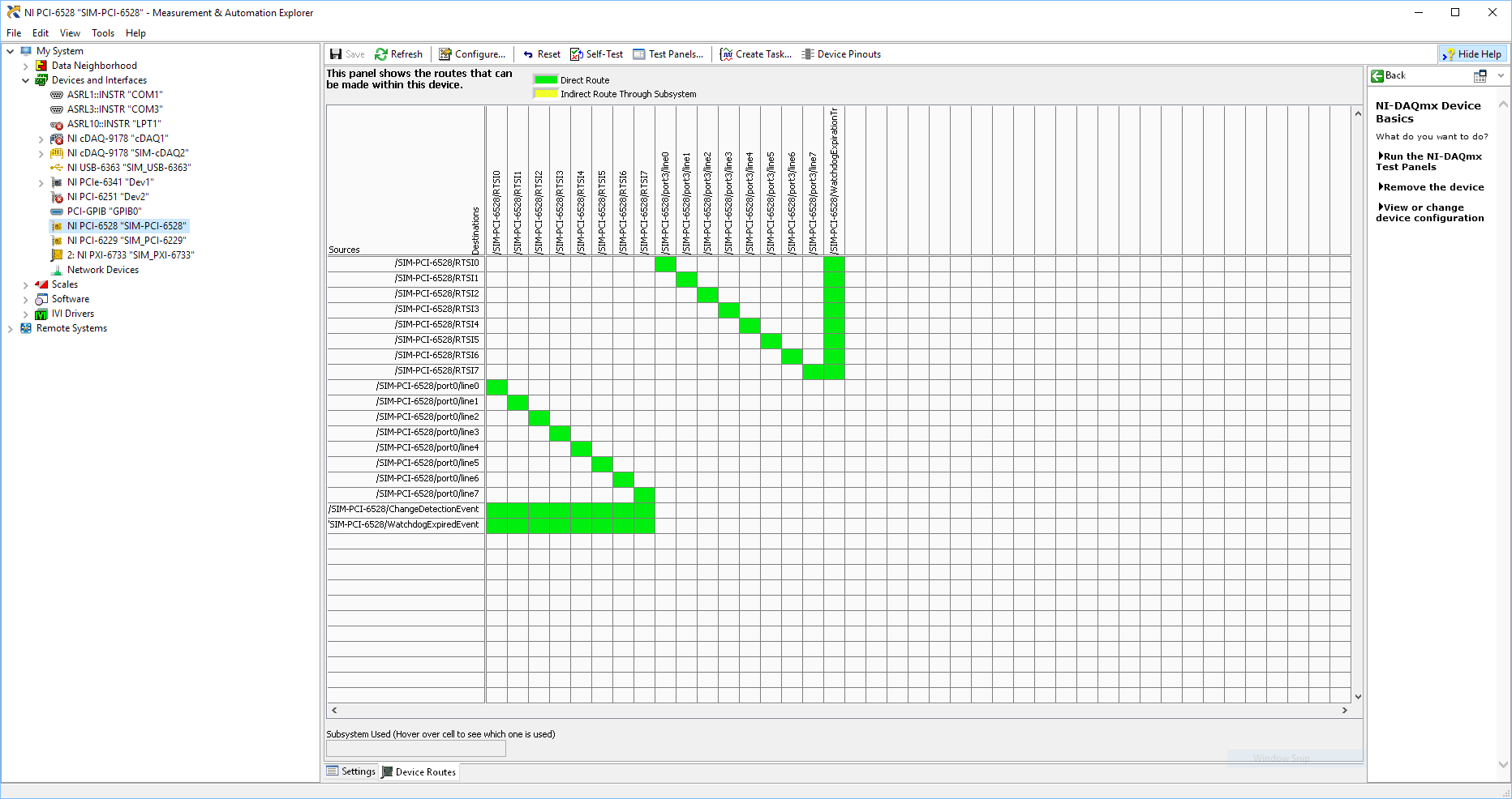
Using SMU 6612 to measure PXI-6528 pulsewidth channel - channel is not available.
Hi all
I use SMU 6612 card counter to measure the pulse width of the signals to PXI 6528 DIO card. These two cards are in the same chassis PXI (NI-SMU-1065). I could measure the pulse widths using the example LabVIEW 2013 Counter - pulse width of reading and (over) frequency example of .vi. However not all channels of the PXI-6528 map appear in the drop-down list of channels on the pulse width can be measured. Try to connect any other channel that those which are available in the drop-down list returns the error. On the PXI card port 6528 0,1 and 2 are entered ports and port 3-5 are output ports. I can measure the pulse on port 0, 3 width and line 0 port 1 and 4.
Can someone explain to me why don't see port 1 or port 2 channels in the drop-down list or force the VI to measure the width of pulse on these channels?
I can plug PXI-6528 external input channels SMU 6612 counter input channels and measure the pulse width, but if possible I'd like to avoid the external wiring between the 2 cards.
Probably not. Unless the routing plan is in fact reversed as it seems a bit sorta that. As stated on my system, you can route * of * a port of entry * to * RTSI, or you can route * of * RTSI * to * one output port. This does not make much sense to me, but that's what I see:
If the routing card * is * reversed, your only likely workaround without physical wire would be to generate impulses in question of port 3. It's pretty clear that 1,2,4,5-tetrachlorobenzene ports have no ability to interact with the bus timing, physical wiring would be the only option.
-Kevin P
Maybe you are looking for
-
ProBook 6650b: locking BIOS PW ProBook 6550 b!
Greetings and greetings good men and women of the impressive computing community. Well guess what? I just bought a little, or should I say slightly used ProoBook. About the nicest thing I ever remember having. Well I just got home and was eager to
-
Change the bios on my hp pavilion dv5-2135dx of 1333mz to 1866mz on the speed of RAM.
I have a hp pavilion dv5-2135dx laptop and I would like to go into the bios and change the speed of the RAM ddr3 1333mz to 1866mz. I bought two chips hiperx plug-and-play of the kingston ddr3 4gig and they are set up to accept the upgrade to speed t
-
How can I increment the index of a table in a formula node?
Hello I need assistance with the node of the formula. I need a table, which increments each iteration of the code in the node of the formula. I need to save the amplitudes. I thought I could do it with i ++; I is the variable for my index. Martin
-
Desktop icons show the notebook to various programs.
-
New machine with OEM in XP and Vista HP disks - can I install both?
I just bought a HP class business that comes with the Vista professional and XP Pro OEM DVD, XP is preinstalled. What I would do is to dual-boot Vista and XP. This is not possible, my secondary desire would be to partition the machine at least before