measure resistance DAQmx 6251
I want to take a measure of resistance with an NI USB-6251 box. It seems possible, but I'm stuck on the excitation source. I use the simple example of resistance - Input.vi VI continued.
Unable to set the current excitation source other than from the outside without errors. Selecting an external source allows the vi to run but I expect to have to provide an external source. What specifications should be and where can I connect? Also, the what pins are measured at the terminals of the resistance?
My project will eventually include an NI USB-6343 instead of the 6251 that I use for proof of concept. The solution for the 6251 apply to the 6343? We're M-series and the other is X series.
Thank you
Mick
I think that the 6251, because it's a M Series DAQ device (i.e. average range), I don't think it's a source of internal current which is used to measure resistance. For this device, you must pass a current known through the device and it will measure the voltage drop on the resistance, giving you the R of R = V / I.
There is also a difference between the resistance 2 or 4-wire measurement - for low values of resistance, which leads using method 4 son to take account of the resistance of the measure.
I don't know if the X-series unit has an excitation source is... I couldn't see anything obvious from the data sheet.
Edit: There is a guide that describes a method to measure resistance - http://digital.ni.com/public.nsf/allkb/408C3D76B0B5690C86256E4500056DDF and one general article here - http://www.ni.com/white-paper/3981/en/
Tags: NI Software
Similar Questions
-
measure resistance with USB-6009
I am measuring the resistance of a photocell using the USB-6009 case. There is an option of "resistance" in the DAQ assistant, but it does not display the values on the right. Here's what I do:
Connections: GND - photocell - ai0
I'm really not sure if this is right, but I assumed that he could measure the resistance as a multimeter. I have not tried doing a divisor of tension and using the Ohm's law.
DAQ Assistant settings: I 'add channel' by using the more blue and choose "resistance". Then, I chose ai0 under USB-6009. I set the max and min values and read it all the time. First problem, playback is generally negative and it flickers a lot. I read about - 1.3 k when I do that with a k resistor 10 regular (not a photoresistor)
Obviously there is something wrong, but I'm very new to all this and cannot figure it out by myself. Any help would be much appreciated.
Thank you!
The 6009 cannot measure the resistance as a multimeter unless you can prove that a current as the wizard by default source is set to. In itself, it can measure a voltage. Then, use a voltage divider.
-
Just installed LV8.6 on a PC and things seem fine except functions > range of measures of e/s does not contain a subpalette NOR-DAQmx. It contains only the Configuration MAX subpalette. Without creating a task, Read Channel, Start, etc etc.
I go through stages during the installation with the DVD drivers and thought that I was installing NOR-DAQmx. MAX said that NIDAQmx is installed on the system. And I can run test MAX on a NI USB-6009 case panels.
What should I do to get access to all NIDAQmx vi? I miss something during the installation or something?
Thank you!
I heard a similar problem as well... Here's the article knowledge base that describes what to do. Let me know if this corrects the problem.
-
Hello:
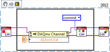
I am able accelerometers signals in a module of 9234, using DAQmx (I leave the joint scheme), which will be part of a program that will include other stages. When the acquisition is stopped by the "stop" button, I measure with a voltmeter between terminals connector BNC, reading 21 volts, which is the excitement of the sensor. My question is: How can I do to cut the excitement of sensors once the samples are acquired?Best regards
Jaime
Hi Jaime,
You can disable released the 9324 excitement by setting the AI. Excitation.Value property to 0.0 (see the following KB: http://digital.ni.com/public.nsf/allkb/3AD6CCE935192B4086256F6B0079CB1F).
Then, once you have set the attribute, you will incur the task to actually push this setting material (normally DAQmx will automatically engage when you start the job, but in this case, we do not want to start the task). Between your VI DAQmx stop task and your VI DAQmx clear task , you must add the following:
- GOT it node DAQmx channel property to set. Excit.Val = 0.0
- DAQmx controls Task.vi to validate your new task settings
-
Measure the resistance with PXI DMM 4072 on different frequencies
Hi all
I tried to get on board various and unable to find solutions for that. I'm trying to measure resistance using NI PXI-4072 on frequencey 1 kHz, but not luck. When I try to use Agilent LCR meter I see the correct value of the resistance.
I've seen a few posts on this but don't have no satisfactory solutions.
In above post, someone said that I can use 4072 DMM OR digitizer, does not have a lot.
Can someone please provide the right path for me to solve this problem.
Thank you
Hello Puneet_K,
I checked the data sheet and the method of measurement described in the specifications of the NI 4070/4072 http://www.ni.com/pdf/manuals/371304g.pdf; indicates that the ability is measured using an alternating signal and select the test frequency range, for example 3 kHz, 1kH or 91 Hz. The resistance is simply measured using a DC signal, and it is often sufficient to measure the internal resistance of a battery. If you need a more flexible control for the measurement, you probably get a card like the function generator and then set a multimeter to measure the voltage and another DMM to measure the current and calculate the impedance of these values.
I hope this helps!
Kind regards
-Natalia
-
How can I use 2530 b and 4065 to measure the resistance between two selected pins?
I want to be able to select 2 corners on a test with 2530 b set-up and measure the resistance between them with a 4065 DMM (PXI all). Ankles in question are each in blocks of 32 different poles, so I can match them in a double configuration 32 x 1 four or 64 x 1 if necessary. I can measure the resistance between several different pine sets as 0 on 33 pine pine, pin 0 at pin 34 pin 0 to 35 pin and pin 1 to 34 pin, pin 1 pin 36, etc.
I understand how to measure resistance between a given pin and Earth using the the 2530 4065/b using the wizard OR-DMM/Switch Express, but it is unclear if I can measure the resistance between the two pins of selected by different user. I am a newbie of labview, used to write things in c#, so it may be something very trivial (I hope).
Any ideas?
Thank you
-Russ
Hey Russ,.
I recommend starting with the following example (located in the Finder the example ('Help' to find examples):)
"" Material input and output"Modular Instruments ' OR-Switch" niSwitch Dmm Switch Handshaking.viBecause you use a scan list, you can simply drag the two connections to the same entry and then the switch will wait for the two to settle before you send a trigger of the DMM... problem solved. For example, to connect the CH1 to Com0 (DMM +) and CH93 to Com4 (DMM), then take a measure, then connect CH38 and CH120 to the DMM, you would use the entry list of scan to the following address:
CH1-> com0 & ch93-> com4; CH38-> com0 & ch120-> com4;
Note You can have as an entry in list of switch module scan. In addition, you can only have a single advanced analysis and a measure full per switch module.
-
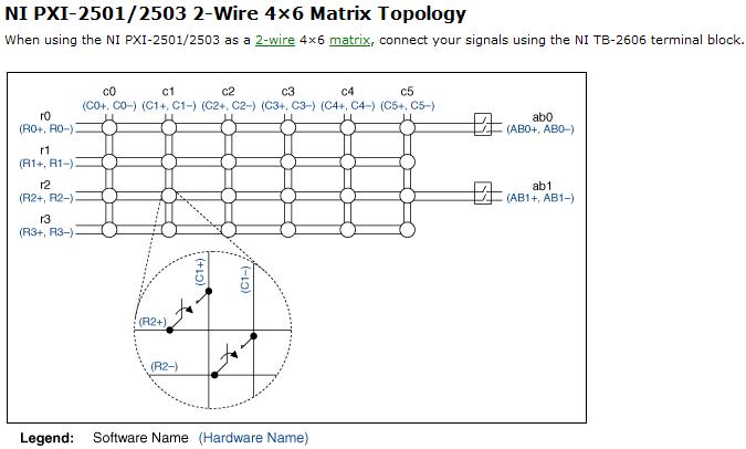
Resistance measurement using PXI2503
Hi, I am looking to understand how PXI-2503 measure resistance of 2-wire matrix 4 * 6.
and I tried several different configuration on my board but I couldn't receive the correct value of the resistance.
Software:
I use the example of LabView8.5 (niSwitch DMM Scanning.vi synchronous switching)
My scan list of entry (c0-> r0) under the switch
between 10000 and resolution 100 m under the DMM
Material:
I tried several set upward,
1. I put a resistor between C0 + AB0 + and r0 + AB0 -; and - c0, r0 - connect to GND, (this configuration gave me some graphics but no resistance)
2. I set the resistance between c0 +, r0 + and AB0 + (they connect) and c0,-r0, AB0 - (but it gives nothing.
my setup is bad? why I could not receive any resistance...
Thanks for any help
Hi Newer104,
The problem may be that the analog bus relay is not closed. Please refer to the following image and note that the ab0 relays must be closed to create a path between the rows/columns and the analog bus.
If I understand correctly, then I recommend placing the resistance between c0 + and c0 - and create the entry list of scan to the following address:
R0-> c0 & r0-> ab0;
Let me know if this solves your problem. Best regards!
Chad Erickson
Switch Product Support Engineer
NOR - USA
-
Hi, I'm working on a project where there partly to measure resistance values in different parts of the circuit. Now, the company where I work currently at wants to get the NI USB-4065 USB. I use visual studio 2005 c# to develop applications and I need to know if I needed measurement studio or are there drivers (dll) just to get the values of resistance and General measures of circuit. I have need the controls or anything, just to programatically read the NI USB-4065 USB key values when I need the application.
Any help would be appreciated. Thank you.
Yes, you can have several NI 4065 DMM in your system. When you use the API OR-DMM, you open the handles separately for each DMM by using its name. His name can be configured inside the measurement and Automation Explorer (MAX).
In addition, you can go ahead and install OR DMM today. It is downloadable for free on ni.com. NOR-DMM (and most of the pilots NOR) supports the simulation. You go to MAX and create your simulated three 4065 s. Then you can start writing your program now. Since these devices are simulated, they will not return the real tensions (obviously) and that it won't react realistic hardware triggers if you use (obviously), but they are pretty close to the real deal to allow you to write a lot of code and become familiar with the API. No need to wait until you get the material - you can be really ready for it by using the simulation.
-
Read a resistance of the diode by vs NI USB multimeter
Hello
I read a resistance of the diode at some entrances to supply voltage
and I found that
to 0.2 V
the value of resistance by NI USB-6212: 200 ohms
the value of resistance of meter: 2 kohm
0.5 v
the value of resistance by NI USB-6212: 500 ohm
the value of resistance of the multimeter: 5 kohm.
Could you please let me know why the values are different by 10 times?
Thank you.
No - we can't measure the resistance in this way.
To measure resistance, you normally spend a current known and then measure the voltage. A DMM will be repeated by generating a little known current and measuring the internal tension. If you provide an external voltage thus, DMM internal resistance measurement will not work.
For the LabVIEW - The USB-6212 can measure the tension. If you want to measure resistance, while the unit is plugged, you need to know/measure current (for example through a shunt resistance) and the tension and then do R = V / I for the resistance. I don't know what the argument of type 6212 if you try to perform a measure of 'resistance', as it is not a source of internal current.
Oh, I thought that this all seemed familiar - here's a similar thread: https://forums.ni.com/t5/LabVIEW/daqmx-resistance-measurement-6251/td-p/3267084
-
Internal resistance on 2800 backplane?
I have a new switchblock 2800 OR 2811 A card that I connect via a Virginia Panel ITA. Before using the switches for my project, I was testing the switches and I found a behavior that I wasn't expecting. I have a 4072 digital multimeter connected to SwitchBlockDev5 c16 and c17. When I connect c16 and c17 through another line in the first attachment (c5 is the other line in this example) then I measure resistance of ~ 200 ohms (I expect something close to 0). When I cross the lines from the bottom of the basket and connect the DMM leads it as in the second setting (where the lines are connected on SwitchBlockDev6 c18) then I measure Mohm resistance ~ 168 (I expect something close to 0 or 200 ohms), if I pass the DMM wires on the second configuration then I get - 4.45 Mohms under my measure. Can someone explain what is happening and what the circuit looks like? Is there some kind of framework, I can do in the software that will give me my desired values when I do these DMM measures?
Thank you
Chall
Chapin,
The 200 ohms you receive is probably because you are using the cable "SH96F - 96M - RES. There are two cables NI SwitchBlock, a 'normal' and a cable with resistance of 100 ohms additional linked internally to the cable by column [two whole columns = 200 Ohms]. This additional resistance of 100 ohms is used to prevent the current overloads. If you use the cable "SH96F - 96M - RES ' and you want to read 0 Ohms, you need to replace the cable with the cable"SH96F - 96M"'normal '.
168 M Ohm resistance you measure is probably due to the missing safety lock Resistance on your test setup. If the resistance of safety lock is missing, connections between the relay in your support of 2800 cards will never connect.
-
measurement time and openness 4132
Hello
I use a 4132 SMU with a switch 2531 to measure different resistance in an electric circuit. I use a brief biphasic pulse of 50ms ~ to measure resistance. My problem is the measurement time if long - it seems that the minimum pulse width I can do is a 30ms pulse in a polarity and a pulse ~ 40ms in the other polarity. I disabled 'way' that knocked 20ms on each phase, but I am still left with a ~ 70-80ms measure, but I wish it were half that, if possible. The only other way I can see to minimize the measurement time is at the bottom of the window opening, but any if I increase or decrease the time of opening, the measure takes about 10 x longer if the opening is none other than 1 PLC.
Attached is the Subvi I use to measure the unique resistance value. Note that first I close the relay to solve part of the circuit and then configure the SMU and then get several measures, one for V (+) and one for the (-) V. This measure will be repeated 15 times in quick, although succession with different closed relay, which means that the SMU gets reconfigured/initialized 15 times with the same parameters, so maybe that's my problem. I have not ventured into the handshake, but I would like to know if there is anything else I can do since the handshaking deal would take a lot of programming. In any case, when I run the VI several times, there are only 8 ms between biphasic pulses, so the reconfiguration may not take THAT long.
I posted a jpg file of the time trace of the impulse it generates (10,000 samples per second). Note that the first phase of the pulse is a different length of time that the second phase: there is nothing in the program that would cause - it would be more logical if the first phase was more time on behalf of increasing the time for the configuration of the SMU. So I have sort of a bunch of problems here: 1) cannot reduce opening time 2) want to avoid a handshake VI if it means hours and hours of programming, 3) uneven pulses. I hope someone can point me in the right direction!
Thank you very much
GimNPC
gimNPC,
As mentioned earlier, you should not call Reset every time at the end of the method. Instead, set the output to 0 c. Moreover, all the attributes that are not changed will not need to be reconfigured, which will speed up the loop a little (maximum, that I would expect several milliseconds).
When you call niDCPower Reset, the opening time is reconfigured. On the 4132, anytime, the opening time is reconfigured, must wait a minimum of time to allow a measure being erased. It is because of the behavior of one of the hardware components that we use. If you prevent the reconfiguration of your opening time during each run, your speed should be improved significantly.
Please let us know if these suggestions help, or if you have any other questions.
Thank you
Tobias Gordon
Software engineer
DC accuracy
National Instruments
-
Differential measurement across the ground of the card NOR referenced output.
Hello guys,.
I have a question, our pure curiosity.
I use map of USB6212 to apply a sinusoidal signal of 10V to a game to the top, then measure the tension between charges.
I'm attching here a simple diagram showing the system. The implementation can be modeled as a combination of RC - r series
Note that I'm also measure voltage R2 in differential mode. Now that I am after is exact phase of monitoring between the two voltages (according to the RC and the R2).
My question: is the correct diagram? I mean - is it OK to measure the voltage across R2 in differential mode with attached as such polarization resistors?
It is one of the lines through R2 is already at AOGND. And AIGND and AOGNd are already connected inside the card, it will be then introduced errors?
or does not at all?
Thanks guys, will be grateful for a quick solution.
You can do this but the differential mode does not have much. Your signal source is single ended. The voltage at the terminals of R1 - C can be measured in different ways. It really is meaningless to measure the voltage across R2 differently because one end is connected to the Earth. Polarization resistance, Rb, are not necessary in this case because the low enough impedance DC railways exist at all entrances.
What I would do, is make two measures ended up alone. AO1 measured on a single channel (AI0). Measure the R1 - R2 junction on the other channel (AI1). Then the input voltage is AI0, the voltage at the terminals of R1 - C is AI0 - AI1, and the current is AI1/R2. You will need to enjoy fast enough that the time between the different measures does not contribute too much to the phase error. It depends on your frequency of signal and eligible errors. Look at the charts of a waiting time to page 2 of the NI USB - 620 x specifications for more information on how to compromise between the speed, accuracy and multichannel source on measures resistance.
Lynn
-
SMU-6363 pressure measurements
Hi guys,.
First post here. I tried to search first for documentation but empty is come.
I use the analog inputs on the 6363 map to make some measurements of voltage. I have 2 questions:
- I know that the channels are limited to +/-10 volts for entries. I have a 25 Volt with a resistance line series regular (50mOhm) sense. I want to do a differential measure resistance across with 2 analog channels. The real tension between the two points will be in the range of mV, but the unique finished voltageon each will be ~ 25 V. Will this work?
- In a similar configuration, but on a 5 volt line can I build a differential measure through a resistance of sense current using 2 channels and then turn around and use one of these same channels for a single measure is complete wrt gnd?
Thanks for your help!
There is a row in the datasheet that States
Maximum voltage of work for the analog inputs (signal + common mode)
±11 AI GND v So with a 25V common-mode voltage, you will hurt your card. The 5V line should be fine.
If you look at Digikey, there are chips specially designed to detect a current shunt. The differential voltage amplifiers will become a simple nerve from the ground.
-
A measure of speed high speed with encoder in quadrature and NI 9401 on cDaq
Greetings,
We use an encoder in quadrature with 360 pulses/turn on the tracks (track A and B) and no trace of Z to measure motor speed at startup. Data acquisition, we use a NI 9401 in 9178 cDaq chassis and a pc with LabVIEW. The problem is that the start-up period is relatively short (less than 1 second), during which we measure speed as precisely as possible. The speed range is from 0 to 10000 RPM.
What type of measurement method that you would recommend.
Here are a few methods that we have already tried:
-Measure with DAQmx CIFreq--> high frequency with 2 counters: speed measurement, but with a very big mistake (+ 166 RPM).
-CIFreq DAQmx--> wide range with 2 counters: good speed data but more slow measurement,
-CICntEdges DAQmx (counting separated the two lanes, speed conversion): very incoherent speed data.
Thanks in advance for your help.
Matej
I would definitely say a 4, the measure of a low freq called option with 1 meter. (Frankly, I've never been
fond of this name because it is useful for freqs much higher than what I expect most people think "low freq".) This
is the method that I almost * always * use for frequency of counter measures. It works really well to capture transitional
variations in speed.
10000 rpm and 360 cycles/rev, you are looking at a maximum frequency of 60 kHz. The frequency measurement mode 1 meter
There will be 80 MHz internal clock by encoder cycle edges, then you will get more than 1000 strokes per measure. The point
that means only 1 number of quantization errors, you can expect<>
Further, you can average overall, say, 10 samples to you give even better accuracy and you could still be a data capture
rate significantly higher than the probable bandwidth of your mechanical system. (The average would just clean the jitter and noise and would not
Hide answer true mechanical characteristics).
-Kevin P
-
Overlapping areas NOR DMM PXI 4070?
We will soon use NI 4070 Flexdmm.
I am trying to establish how much on a range of resistances that can still read a resistance value,
For example, could I measure resistance of 105 ohms on the beach of 100 ohms or resistance 1050 ω on the 1 k range?
I do not see this information published anywhere... and Yes, I have reasons for that

Thank you
Alan
Perfect answer - just what I was looking for thanks!
Maybe you are looking for
-
delay in the structure of the case
Hello I use a structure of cases within a while loop. I want to put a delay of about one second whenever the case goes wrong (it must remain false until 1 second) then comes to the usual routine. I tried to use the function wait (ms), but then it eff
-
Microsft award-2011 is a scam?
Please see the mail and help below me on these issue. Best looks kh.md.belal hossain - of: * e-mail address is removed from the privacy * subject: Online Award 2011 Date: Wednesday, April 20, 2011 16:31:48-0700 regular internet user! This is an offic
-
Attempt to acivate/install files for East Asian languages using Control Panel. Pop-up message asking home ed. SP3 CD to be inserted in the CD drive. Since the SP3 update has been downloaded with automatic updates, I have no CD. How to solve the prob
-
I have an OOB layout that has all the ports from the switch controlled by the same profile. I would like to be able to place clients on a network, printers on one another and tell on another unix systems. Right now I have a filter that lets the clien
-
Error after update Blackberry AppWorld for blackBerry Smartphones
I received notification yesterday to update BB AppWorld, in order to be the owner of BB little good I am, I immediately did so, since the update, whenever I try to use BB AppWorld I get an error: Uncaught exception: java.lang.NoClassDefFoundError Not