Measurement of encoder module?
Hello
I choose an encoder for my project the other day, but I don't know which module to search. I really appreciate the help of anyone with this issue.
You will find the link below for the specifications of the encoder.
http://www.Encoder.com/literature/datasheet-260.PDF
Thank you.
Tags: NI Hardware
Similar Questions
-
What compactDAQ for optical encoder module
If I have an optical encoder with a resolution of half a plan on using it for the speed or position and degree, can anyone recommend a CompactDAQ/CompactRIO module? LabVIEW would be fast enough to keep up if Let's say your device runs at 50 rpm?
Hi NSL22,
What is a quadrature encoder that displays voltage TTL levels?
If so, I suggest a 9401 or 9402.
50 rpm should be no problem (half a degree of resolution would give rise to a 600 Hz signal, these cards can take up to 10 MHz).
Do you just need to display the position of the encoder? Compact DAQ has embedded counters that handle most of the work so that the software should not have to do much. If you are using Compact RIO you program yourself on the FPGA. If you want to provide feedback based on the position of the encoder, Compact RIO would probably be the best option. If this isn't the case, DAQ Compact should be more than enough, depending on what exactly you need to do.
Best regards
-
WiX Installer Measurement Studio merge modules
Is there a tutorial somewhere on how to create a WiX Installer for a Measurement Studio application similar to the http://digital.ni.com/public.nsf/allkb/ED87C183E056CAC386256DF1004E54C6Knowledge Base article? I have an application Measurement Studio c# which I am creating a WiX Installer for and I have problems to get the measurement of inside studio merge modules. I get errors ICE30. I'm using WiX 3.0.
Hi d_sdl,
Our merge modules should work in WiX, as I have tested this several times. When you say that you have found ICE30, that fails your build? As you probably already know, one of the nice features of WiX is that you can set a flag so that whenever WiX compiles and links your source, it works ICES on them. This allows you to catch problems early in your development process. I guess you do is put the WiX linker fails if ICE warnings/errors are thrown. You can configure WiX for actions based on ICES advice you get. What is important is that you can turn off this setting, but it depends on how you are nvoking WiX (i.e. through NAnt, MSBuild, Votive, etc.). In any case, there are different ways to disable this option. What I would say is to disable the option, or be specific about which ICES to ignore. This decision would be to the you. The key is to understand what actually means ICES and determine if they are legitimate questions.
ICE30 can indicate a variety of different things, but a common reason corresponds to the entries of the SFN. Some of our merge modules are always generated through Visual Studio deployment projects and VS created RFU very well. Thus, you're left with SFN entries duplicated in the MSM. Long file names are different, but the short file names are the same. WiX does this correctly which is nice, but unfortunately we can't convert some of these modules more MSM because of VS restrictions and limitations, that we found. It would be nice if better RFU created VS.
Attached is a zip file that contains two projects that are:
- C# project that produces the binary file that the Setup program will install
- Project of WiX that creates the MSI file
First, be sure to build the c# project. I tested the MSI that result, and it works very well on a target system.
Note If you want to load the wix project, you must have the final version of Votive on your system.
Best regards
-
High speed continuous measurement of encoder with sampling frequency of 1 kHz
I am able at all times the position of a linear encoder using a PCI-6602 counter card, and I need to know how to set up so that the counter rotating at high speed, but the data is inserted into the buffer at a frequency of 1 kHz. I am able suddenly to a hydraulic cylinder, and I am not concerned about the event recording to high frequency except to the extent where they throw off the number considerably if the equipment does not run fast enough to detect all the impulses of the encoder.
Now, I think is that the external sample clock signal control (routed internal pulse output counter) time rate whereby the equipment detects the impulses of the encoder and the rate at which it inserts data into the buffer. With a pulse 100 per inch encoder and a sampling frequency of 1 kHz, the extended final position of the cylinder is turned off by +/-0.15 inches, which is unacceptable.
I need calculate a speed of this information, so I prefer not to use software timed sampling to control this (it's more difficult programming for other reasons as well - several asynchronous measures). Any ideas on how to configure the hardware to count faster than the speed at which she inserts counties in the buffer?
OK, you're clearly on the right track here, so I will focus on some details.
1. How do you know that the +/-0.15 "differences are * measurement error rather than * error of movement? Why wouldn't be an accurate measure and a proposal which can vary slightly from the nominal value?
2. I wonder some all electric noise and defects that may produce false edges. The fact that the behavior was better by using a sampling rate limited (200 kHz) in the digital inputs may be that some of these flaws were so short that they were never captured.
I did a ton of work with the Commission to 6602 encoder and I can certainly confirm that count equipment is sensitive to the edges in a few tens of MHz. (I know its 80 MHz for edge counting, but I think I remember that it can be of the order of 20 to 40 MHz to accommodate the time of signal propagation extra of the quadrature decoding circuit).
A small point of clarification. You're talking about the speed at which the meter "works to. The value of count is a register whose value is changed completely by the circuit, * independent * of the sampling frequency. If you enjoy with material-clocked County in memory buffer or interrogation of software without buffer not a bit for circuits that increments / decrements the value of the counter register. (In other words, I am completely convinced that you would get commensurate with position end even if you took only 1 sample software-polled after the end of the move instead of sampling at 1 kHz all the way through.)
So, if the value of the counter is disabled, it is because the circuit detects producers of County of the edges that shouldn't be there. Something you can try is to set up digital debounce filter for input lines of the PFI corresponding to the encoder Source inputs and to the.
-Kevin P.
-
How can I import my IE Business modules in Firefox?
My company has some add-ons that I use in IE, but I prefer FF. How can I get the same Add-ons in FF?
You cannot use the modules of IE in Firefox, each browser has their own encoding modules.
-
Capture high speed encoder data
Hello
I have a motion control project where I would record the position data. High speed capture is limited with sampling frequency of 2 kHz. But I have to save a lot more than higher speed.
I read that there is another option that connects to the motion control card (I use a card PCI-7358) and the map of data acquisition using a RTSI cable and channels A and B of the routing of the data acquisition card encoder using the RTSI lines.
I have 6143 and 6280, 7358 PCI DAQ cards and a RTSI cable.
Q1. Which card is better to use? 6143 or 6280?
Q2. When I look at the examples, I have seen that its possible to phase has the traffic and signals of the phase B of an encoder for the RTSI line with Signal Select.vi. But I couldn't find an example on how to read of DAQ card.
Q3. How can I contact the encoder position phase has and band B pulses which is acquired from the DAQ cards?
Concerning
Hi serkanb,
The 6143 has no support for measures of encoder quadrature (although you can run a task of count of edge and use the B signal as a line up/down to get a similar effect). If you are interested, we'll find more information here (the 6143 uses the same SC I ASIC that make the E Series DAQ devices).
It doesn't really matter too much since you have a 6280 that supports quadrature encoder measures (he uses the STC II ASIC). To answer your direct questions:
Q1. The 6280 is better (see above)
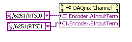
Q2. You need to use a channel DAQmx property node to choose what terminals to use for your task of encoder:
Q3. I would like to start with an example of the expedition:
Help > find examples... > input and output material > DAQmx > counter measures > Position > measurement Position.vi
You insert the property node before starting the task (but after the channel is created).
I hope this helps, if you have any questions do not hesitate to post back!
Best regards
-
measure temperature pt100 with cRIO9211
I can measure the temperature with a pt100 in cRIO9211? I wanted to measure of 0 ° c to 100 ° c...
Can someone please show me how?
Thank you very much
Best regards
Hello
Thanks for posting your question on the forum of National Instruments.
Unfortunately, you can't have a RTD (generally with a PT100 probe) measure on a module 9211.
9211 module is dedicated to the use of thermocouples.
I suggest that you use a 9217 or 9219 rather (more information here).
I hope this answer will help you.
Best regards
-
Prevent the reset to the Initial Angle encoder
Hello
I currently have an enoder connected to a meter entry on my data acquisition card. For my approach, I need the ability to start/stop the task to read the encoder. My problem is that whenever I restart my task, the encoder is reduced to zero (My Initial Angle). Is anyway to avoid this?
Thank you
Paul
Your reply to #5, it is clear that you should NOT stop the task when you want to go down to a slow sample rate. I've got 2 basic approaches to suggest:
1. approach HW: you use a counter to your measurement of encoder. Is your other available counter to generate your sample clock? If so, you can simply change the output frequency of the counter on the fly to change the sampling rate according to the needs. A possible disadvantage is that the data buffer real CQI will provide no clue as to which the rate has been used for which samples. If this is a problem depends on your application.
There is actually more complicated possible method based on using a dummy AO task it (if you don't have a real AO NI hardware task) as a sample clock because AO rate can also be updated on the fly. Then, you can use your 2nd meter to measure the clock, so you should have a record of all the timestamps. You must be sure to keep your starts and readings in sync, but it's certainly doable.
2 SW-approach. Always taste the same pace and always retrieve data from the buffer quite quickly to stand. But at the time of 'modes of sample' slow, extract only the portion that you care to keep. Overall, this approach is probably more simple, but the former is too clever not to mention.
You were already on track fundamentally with your thought to share the sample clock I. What you might not have realized, it's you POUVEZ stop the task to HAVE (manufacture of the sample clock stop) WITHOUT stop the task of the RTC. You can restart the AI at a different rate. During the time that the task of IT is stopped, there is no sample clock pulses causes encoder CTR values to be buffered. However, the register real account will always be increment/decrement properly for track position. When you restart the AI at a slow pace, you just respond to sampling/buffering the position values.
-Kevin P
-
Cannot find the dependency of the module with signature
Hello:
I use Visual Studio 2008 sp1 and Visual c#. The program works very well in environmental development and as a standalone .exe in the development computer and another in which he is also VS 2008 sp1 is installed. But if I try to run the program as one demo on another machine without VS2008, it gives me a module not found message as soon as it starts. If I delete the references to AIChannelCollection and ChanType, the program load without error. It does not matter whether or not the target computer has MAX on it. All machines are Win 7. I do not actually use Measurement Studio, but it seems that the classes are somehow associated with it. It seems that the program generates the error as soon as he calls a method with ChanType or AIChannelCollection in it.
I also get a warning on the construction of the Setup project:
Fo could not find dependency of the module with the signature "Microsoft_VC90_CRT_x86.0138F525_6C8A_333F_A105_14AE030B9A54
In my C:\Program Files (x 86) of the \Common Files\Merge Modules directory, I present Microsoft_VC90_CRT_x86.msm indeed. (589 KB, 15/03/12)
In detected dependencies, I have:
Microsoft .NET Framework
microsoft_vc90_crt - x 86 .msm
mstudiocommon.2008.msm
mstudiodaqmx.2008.msm
I tried to add policy_8_0_Microsoft_VC90_CRT_x86.msm, then policy_8_0_Microsoft_VC90_CRT_x86.msm without success. The warning persists little matter what I do, and the program will work very well on a computer with VS2008, but not otherwise.
Help, please.
Thank you.
Tom
This problem has been resolved internally. For reference:
The Measurement Studio merge modules have a dependency on the Visual Studio merge modules. (NOR) must be given a specific signature and version of what our modules-dependent (for example, we cannot say something like "we depend on this signature of wildcards with this generic version; "This is a restriction on the level of the Windows Installer). What happens is the following:
1 Microsoft released an update that changes the signature of module of the MSM that we are dependent (e.g. it's bad to do because its existing customers as use breaks)
2. where Visual Studio will create a Setup project, it looks like our MSMs ModuleDependency ¿and attempts to locate the MSM. The problem is that the Microsoft Visual Studio MSM update have a different signature/version and so Visual Studio cannot locate the MSM. So the MSM Visual Studio don't get included in your Setup project.So, basically, there was a kind of update Microsoft (probably to VS 2008 SP1) which updates the modules that depend on our DAQmx merge modules. As a result, the old buildings no longer exist, so the Setup program creates a warning and fails finally when trying to run on a target computer. There is also a forum link below that is this number in case you are looking for more information or need a different version of merge modules:
-
The USRP CSD requires the LabVIEW Communications?
I recently installed LabVIEW 2013 on my machine, as well as a whole bunch of toolboxes:
LabVIEW English 2013
VI Package Manager
Module LabVIEW Control Design and Simulation 2013
2013 LabVIEW Datalogging and Supervisory Control Module
2013 LabVIEW MathScript RT Module
NI LabVIEW 2013 LEGO (R) MINDSTORMS (R) NXT Module (in English)
Module OR Vision Development 2013
Module LabVIEW FPGA of 2013 (English)
Xilinx toolchain 14.4
Module time real LabVIEW 2013 (English)
2013 LabVIEW Touch Panel module
2013 LabVIEW Robotics module
Software OR SignalExpress 2013
LabVIEW Sound and Vibration Measurement Suite 2013
Module LabVIEW Statechart of the 2013
LabVIEW 2013 for myRIO Module
Toolkit OR run real time Trace 2013
2013 LabVIEW System Identification Toolkit
LabVIEW Toolkit 2013 Digital Filter Design
4.3.4 for LabVIEW Modulation Toolkit
2013 LabVIEW VI Analyzer Toolkit
2013 LabVIEW Database Connectivity Toolkit
2013 LabVIEW Report Generation Toolkit for Microsoft Office
LabVIEW Spectral Measurements Toolkit 2.6.4
2013 LabVIEW Advanced signal processing Toolkit
LabVIEW 2013 PID and Fuzzy Logic Toolkit
Kit filter LabVIEW Adaptive, 2013
Toolkit LabVIEW DataFinder of the 2013
2013 LabVIEW Desktop Execution Trace Toolkit
LabVIEW 2013 Multicore analysis and matrices hollow Toolkit
LabVIEW 2013 power electric Suite
Toolkit LabVIEW 2013 GPU analysis
Biomedical Toolkit LabVIEW 2013
Module LabVIEW 2013 OR SoftMotion
NEITHER Motion Assistant 2013
NEITHER Vision Builder for Automated Inspection 2012 SP1
OR DIAdem Professional 2012 SP1 (English)
LabWindows/CVI 2013 development system
Module time real LabWindows/CVI 2013
LabWindows/CVI Spectral Measurements Toolkit 2.6.4
Spectral measures of LabWindows/CVI DURATION 2.6.4
LabWindows/CVI SQL Toolkit 2.2
Toolkit for processing Signal of LabWindows/CVI 7.0.2
LabWindows/CVI PID Control Toolkit 2.1
Execution of LabWindows/CVI Profiler 1.0
Measurement Studio Enterprise Edition for Visual Studio 2012 2013
General safety NI Patch 2nd quarter of 2013
NEITHER TestStand 2013
NEITHER ELVISmx 4.5
NOR-DAQmx 9.7.5
Xilinx 10.1 Compilation tools (requires the build tools additional Xilinx DVD)
Device drivers or - February 2013I tried to follow this tutorial with the USRP 2932, coming soon, but I found out later that I have seem to have none of the LabVIEW Communications. No not those who prevent me from using the USRP radio? If not, then is there any restrictions on what I can do with the radio without communication?
Hi BreadLB,
The link to the tutorial you posted is based on LabVIEW Communications System Design Suite, a new software environment designed to accelerate the prototyping of the algorithm and stable air. It is a completely separate and independent of LabVIEW environment. See my post here for more details. You can also download a free 30 day trial copy here. Your hardware is supported with LabVIEW and LabVIEW Communications.
The 2932 NOR is a network based USRP, and there a small on-board FPGA. For this reason, the FPGA on that specific product is not a target of LabVIEW FPGA. The NI 294 x / 5 x family has a large Kintex 7 FPGA and can be programmed using LabVIEW FPGA and LabVIEW Communications, as in the tutorial you posted. The 2932 OR can be used with your host PC and LabVIEW for a variety of applications. Unfortunately the tutorial that you have linked to your post requires the NI 294 x / 5 x hardware and Communications of LabVIEW. If you have questions about a specific application for your 2932, please post more details and we would be happy to help you.
-
Sample USB - 6343 Counter clock
I use a USB-6343 CTR0 to measure the angular position. I expect to ~ 1 million encoder pulses (or account) per second. What USB-6343 clock signal would be preferable to use the counter sample clock?
Dar Hi,.
At what resolution do you need measure the angle?
One of my colleagues has compared the maximum sampling frequency on the counters of series X USB to be approximately 8 MHz for a single channel, continuous operation for 10 minutes. However, if the signal that you intend only generates pulses at 1 MHz, 8 MHz rate seems unnecessary because you will receive the same reading several times.
Concerning the two methods you mentioned, either would not be possible:
(1) you could count the external signal and sample at regular intervals. For example, if 10 kHz sampling you'd expect to see ~ 100 strokes per sample if clock signal is 1 MHz.
(2) you can also use the meter to count a time base internally (for example 100 MHz) and the sample out of your external signal. Thus, during a period of your external signal, you expect to see 100 graduations of the time base.
It seems that what you're trying to do is to measure the frequency of your encoder at regular intervals. To do this, I suggest you actually a variant 3. X series cards support a measure of frequency clocked for example (see the X Series user manual). The card has two occurrences of the external signal as well as occurrences of the internal time base known and uses it to determine the frequency. The one caveat is that the signal you are measuring the encoder must be at least two times faster than the sample clock signal. I suggest to use Freq Out or another counter to generate the sample clock.
Best regards
-
scalingSwitchArray & non-visible led table
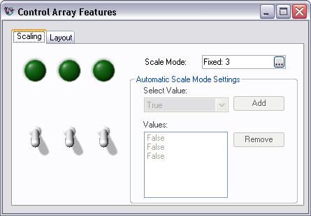
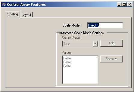
Hello, I have a problem with scalingSwitchArray, led table two user interface elements are visible on my development computer. But if I start the exe on another computer, I can't see the items as shown in the following image. I tried to change the appearance of windows but I have not achieved any positive results.
The following program is an example of
\MStudioVS2005\DotNET\Examples\UI\WindowsForms\ControlArray
Hey jeschki-
The best place to search for dependencies and deployment information is in Measurement Studio titled help topics 'files of XCOPY deployment measures Studio .NET' and 'fusion of measurement Studio .NET Modules'. "" These two documents are found in the Measurement Studio help collection as follows: the the Studio help OR measure "Deploying Applications" Modules merger and deployment of files.
Because your application uses 3D styles, you need the mesa.dll of the unmanaged dll.
NickB
National Instruments
-
Configuration of the basic Source of time to master for the 9234
I have several cDAQ modules I use to collect data. I use vi to Write can Express to save data to a file of PDM.
When you examine the recorded data files, the measured data from NI 9215 provide pleasant timestamps to match how the DAQmx task has been set up--delaying the sampling frequency of 1000 with a 1 ms in the While loop. However, although in the same vi - different tasks, but the same while loop - horodateurs of the NI 9234 do not correspond to the task of DAQmx implemented - sampling frequency of 1000 with a 1ms delay. After reading the material provided with the NI 9234, I found that maybe the machine clean master Timebase Source. There were documents that says he can be configured to be originally of Timebase of Master for the other modules:
Configuration of the basic Source of time of the master for the NI 9234 (Interface FPGA)
It is desirable to have the timestamps for data measured across all modules to match. We do not have the FPGA Module for LabVIEW. Is there a method in LabVIEW for all modules use the same master time base Source? I assumed that because all the data collection has place in the same while loop by using the time delay of 1 ms it was forced through the code. This hypothesis seems incorrect from my review of the PDM data files.
The NI 9204 provides a trigger only.
Software:
Windows 7
LabVIEW 2010 SP1
Material:
CDAQ-9174 chassis
Slot 1: NEITHER 9204
Slot 2: NEITHER 9215
Slot 3: NEITHER 9234
Slot 4; Vacuum
Hi MgDAQ,
An important concept to note is that the 9234 uses a delta-sigma converter and a clock of oversampling to read analog data. There is an inherent delay of entry due to analog and digital filtering built-in. Since the 9215 has a lower resolution there will be a lag the 9234 and 9215 finished. I've included some resources below:
What are the for the NI 9233, NI 9234, and NI 9237 valid sampling rates? : http://digital.ni.com/public.nsf/allkb/593CC07F76B1405A862570DE005F6836?OpenDocument
Synchronization of DSA, S and X series devices with a NEITHER-DAQmx single task series: http://digital.ni.com/public.nsf/websearch/78E44565FD87E7D686257108007F94F8?OpenDocument
Synchronization with NOR-DAQmx of acquiring dynamic signals (DSA) products:http://digital.ni.com/public.nsf/allkb/A133ED27DF9BCC5986256F2E004BA342?OpenDocument
Have you tried to put two modules in the same spot? Alternatively, you can export the sample clock 9234 and tasks installation separately.
Best,
CARISA
-
NI 9205 analog incorrect values in multichannel mode
Hello everyone
I am actually measuring 10 battery cell voltages (which are connected in series) with a NI 9205 (slot 1) in a frame NOR cDAQ-9172.
The voltage of each cell is measured in differential mode with channels 0 through 7, 16 and 17. I have no connection to the NI 9205 COM Terminal.
The other modules in the chassis are NI 9217 (2 modules, slot 2 and 3), NI 9481 (4 locations) and NI 9401 (5 location).
In my LabView program, I put all the channels of the NI 9205 and NI 9217 modules in a single task, because a single task can function both for the measurement of analog input.
My problem is that some of the values measured by the module NOR 9205 do not correspond to reality. All of the tensions 10 cells is about 2.60 V (measured with DMM). But, for example, channel 2 shows 2.67. Some channels are right and others are not.
I tried to vary the frequency of sampling, but this does not really solve the problem.
For example:
Sample rate = 1000-online channel 2 = 2.72 V
Sample rate = 100-online channel 2 = 2.67 V
Sample rate = 10-online channel 2 = 2.67 V
Then I tried to put all strings in a single task and allow a task after another. And then it worked!
But data acquisition is so slow, when you create a single task for each channel and that's why I prefer the way with several channels in a single task.
I don't know if my wiring should consider all connections to the Earth!
Thanks for any help!
Concerning
Socki
Hey Patrick
Your index really helped out me of a jam.
I had to reduce the frequency of clock to convert my module to HAVE. Now, it works great!
Sampling rate is 20 and convert clock frequency is 200 (for 10 channels)
The vi from the following link shows how to change clock frequency convert it (Set convert Clock.vi):
http://digital.NI.com/public.nsf/WebSearch/42484E84DA98053686256D32006E0494?OpenDocument
For my module, I had also to choose and connect the "active devices" on the property node DAQmx-Timing.
Thank you!!
Concerning
Socki
-
HY all!
I have a few questions using Xilinx compiler tools.

The reason why I want to use FPGA is to get the analog measurements of two modules NI 9205 and also filter these measures. Modules are configured to run in terminal diff mode, while the other parameters of this module are set to default values (+/-10 V etc.).
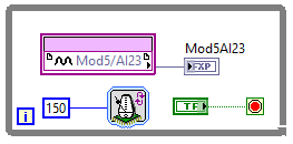
2.1 when I try to compile the program easier - read one analog measurement every 150 US, see the figure below - just compilation takes too much time, namely fear for a few hours, specifically, compiling stucks on mapping. I followed my PC performance, processor is about 20% 3.84 GHz, while the memory is on 10% 31.9 GB. Q1: is it possible to configure the compiler to use as many resources as possible PC?
I'll post probably questions once I managed to get this simpler program to work

Thank you in advance!
Best regards
Marko.
Hello
What operating system do you use? I read somewhere on this forum that windows 8 and possibly windows 10 are not taken in charge by xilinx compilator.
I have simular problem faceing with the compilation of the code. On Windows 8 compilation take over 50 minutes and not finished yet. Then tried to compile the same code on Windows 7 it only take 10 minutes.
Maybe you are looking for
-
Satellite A60 restarts automatically displaying a blue screen
I have a Toshiba Satellite A60 two years old, recently, I noticed a problem where suddenly the computer restarts automatically, in the first, showing a blue screen with white text for a glimpse of a second. Also what difference does update the BIOS?
-
Access my account to Games for Windows - LIVE 3.0
Whenever I try to log in with my account to Games for Windows - LIVE, an error occurs. He said: I can not connect no problem first of all an account. My Xbox.com account, however, is in perfect condition (and it is comprehensive, as well). I really d
-
What type of USB cable is needed for the SX600?
I recently bought the PowerShot point HS SX600 and pushing and it didn't come with a USB cable. I tried different cables I have, but none of them does not output on the camera. Is there a specification that I ask for when I go to the electronic store
-
Series HP laserjet 4050 N PCL5: laserjet "in an error state.
I don't know if mine is a product of the company. I have not used the networking with him. Recently, when I try to print a document, I get the message "error on HP LaserJet printing" or "printer is in an error state." The printer prints a page of con
-
Windows XP stops by a complete analysis of the system
Under Windows XP. Whenever I try to run a full scan of the computer system will stop. This occur during execution of Microsoft and Norton full scan of the system. Must unplug computor and reboot several times, sometimes over an hour so he could resta