Nibbles bits bytes
I have Windows XP Professional Version 5.1 Service Pack 3 and I need to know whether it is a 32-bit based or 64-bit operating system. I am about to install Trend Micro Viorus and Anti-Spyware, and I need to know to click on 32-bit or 64-bit. How will I know if my software is one or the other? (Start-run-winver does not help)
Above is the link for the XP Newsgroups.
For any other question of XP, you would be better to show them in the XP Newsgroups.
These are the Vista Forums.
Click Start > right click on my computer > properties > General > under the system: if it does not say that it is 64-bit, it's 32-bit.
MS never bothered writing it is was 32 bits!
See you soon.
Mick Murphy - Microsoft partner
Tags: Windows
Similar Questions
-
Creating a string of bits to send through questions series VISA, complete noob here...
Hi all
I'm trying now, to browse the values I have on my collection of GUI and with these, construct a message to send through VISA.
I have the usb-> rs232 cable and NO, and I have attached a connector, with the pins 2 and 3 tied together so that I can loopback and see the messages I send.
I'm supposed to (from the instructions that I read on a design doc) will send a message of length of 24 bits.
And please bear with me, I've never worked on this low a level before, nor with the serial interfaces, so I can be completely off on how I'm doing... and this is my
first really relay with LabView for this project.
I have some time execution of every 20ms in a loop.
I have a structure of the event looking for user actions on my front.
I also breast that everything in a loop, a flat sequence structure... my assumption was, every 20ms, the flat sequence structure would run, except where it is interrupted by an event... that could trigger and then continue with the flat structure...
I have seen that the entry VISA (and read) take a string.
So, I started the flat structure with build my string of bits/bytes outgoing... first section is coded hard and then, through the two sequences, loop it and based on the values of the controls within each cluster, I concatenate to my outgoing string... in which case, I send by the visa by the closure, and post it on the message indicator.
It seems that I can send on only 8 bits at a time through VISA... so, I try to understand (and I wonder people with the req on this part) why they said to send such a long chain... or am I supposed to send each message of 8 bits, one at a time?
If one bit 8 message at the same time, I wonder how I have let him know when I am finished? I have heard and read things about start and stop bits, but I don't know where to put them.
In addition, is the string that I'm supposed to put them together to send something waiting for data series bits/bytes? I saw a reference to a string of bytes while the research, but I Coulnd't ' t find a piece of string byte on the pallets.
And when I run the present (a simpler example of my real application, simply to show here the parts I am trying to figure)... the message echoing again to me is:
111000010000\n
When if I have all the tubes with a value in them... I want to get something new like:
1110000111111110111111110\n
I'm also noting that messages do not seem to be transmitting every 20ms... seems only to get a message back when when I trigger an event, as the option switch on the LED.
In any case, I'm confused, I think that, on certain basic principles and hope someone can maybe send me some links or give me some advice on where I'm wrong so seriously...
Is my construction of the right to follow path string message?
Is something wrong with the flow of the program... the events + flat sequence structure?
I received this property by searching for forums and other papers OR, but I'm stuck sort of and confused I think on some concepts with read/writes...and possible VISA my flow control.
Any suggestions and/or links GREATLY appreciated.
Thank you
Cayenne
PS. Some asked to record for older versions, so I enclose a copy saved to more 2011 v10
Cayenne,
Your sequence structure is not necessary. You have a dependency on the data, as well as the structure of sequence is not really do anything for you. Seems to me that what you want to do is to build the table of your clusters that you already own and send the table directly in a > 0? function. It will accept berries and an array of Boolean output. You can then use the Boolean array to the Number function to create a U8. Do this for each of your clusters and integrate the results in a table of U8 and fixed data. Then use the array of bytes to the string function to get a string to pass in the VISA to write it. Without loops or the necessary structures. Any additional manipulation you need, I recommend to the byte level.
-
A number by breaking into its component bytes
Hey, guys.
I am aware of the function of split number. But my problem is a little different.
Let's say I have a 12-bit byte. It is something like this: 0000-1111-1111-1111 or 0FFF.
When I use the split number, I get 0F and FF.
But I intend to have something like this: 0011-1111 + 0011-1111.
I mean, I want to break my 12bits in a 6 number + 6bits, not in a 4 + 8.
Should what tools I use to have this result?
Thank you!
1 AND 2 ^ 12-1 (12-1) so that you know that you want to keep more low 12 bits (if you want)
2 AND 2 ^ 6-1 to return the 6-bit low
3 right-shift 6-bit to return the upper 6 bits
Or use the rest and the whole quotient.
Divide by 2 ^ 6, quotient is higher, the rest is less
-
I hope you'll forgive the newbie question, but my education is in aerospace engineering computer...
I have a verified specification document that tells me that for a source of data to start to transmit control data, I need to send it the following command via UDP:
Normal 0 false false false MicrosoftInternetExplorer4 / * Style Definitions * / table. MsoNormalTable {mso-style-name: "Table Normal" "; mso-knew-rowband-size: 0; mso-knew-colband-size: 0; mso-style - noshow:yes; mso-style-parent:" ";" mso-padding-alt: 0 to 5.4pt 0 to 5.4pt; mso-para-margin: 0; mso-para-margin-bottom: .0001pt; mso-pagination: widow-orphan; do-size: 10.0pt; do-family: "Times New Roman"; mso-ansi-language: #0400; mso-fareast-language: #0400; mso-bidi-language: #0400 ;} "}
I think I begin to understand the behavior of bits, bytes and such with LabVIEW. Kind of confusing without experience in the calculation...
According to the documentation - when you use the boot command - there is no payload data required; It is ignored by the data source. I guess only for these items remaining after the 4th element are that they are simply placeholders to know the data source it is a completed order, or that the original programmer copied the picture of one of the other orders (requiring the payload data) and those who are just residual values he knew have been ignored and never bothered to remove. It would be consistent with the just-get-it-done approach favored this programmer.
Thanks for the help. I think I can interpret the other commands for this data source now.
See you soon.
-
integer of 32 bits carried by gpib
Hello
I currently write software for the acquisition of data and control for a testing machine Instron with a GPIB Bus with Labview. The machine is not the youngest, so I cannot use the 488 commands, not the VISA controls. My control software works this far, but with the acquisition of data, I encountered some problems for which I couldn't find a solution that far. I just taught Labview to myself two months there, so sorry if my questions seem silly to you. I searched the forum and the internet and could not find an answer to them.
So here's my problem:
I like to read my Machine with the command "GPIB-read" data, it gives a string, so I gues it automatically assumes that the data are encoded in ASCII. Well, the machine uses its own coding, described in its manual! I read the header of the measure (it's '#I' in the ASCII format), after that there is a signed 32-bit integer that represents the length of my block of data. Then there is a 16-bit byte and after a lot of 32-bit signed bytes that represent my measurement data. There is no mark of separation.
When I got out, I just get a string of crazy ASCII code (outside the "#I" at the beginning)
My approach to decode the message, that is that:
Convert the ASCII code in binary code (not with Labview, I couldn't know how it works, either. there at - it an easy way to do this?), so I ignore the first 64 Bits (2x8Bits of the entire + 32 bits wide + 16-bit header) and then I try to divide the string into an array of 32 bytes long strings and see if the data is good. In my assessment, I had three values that when it is constant, it should be just three alternate values. I always get the wrong data and especially not, I work with Labview, but later I have to because I want to view the data in real time.
There is a lot of work and I just wanted to know, if I'm on the right track or if there is a simpler solution. Later, it shouldn't be a problem to display an array of integers as a wave, right? Is there any advice or you can give me any advice?
Sincerely,
Simon
- Request VISA 488. So I don't see why you can't use the VISA.
- A byte is 8 bits. There is therefore no such thing as a 16-bit byte. It's a Word.
- The string Unflatten is your friend here. You can use it to decode every part of your order. And since your actual data is just a string of 32-bit words, you can use the Unflatten of string to turn that into an array directly, just to make sure "Data includes table size" is set to false.

-
How to read the 16 bytes directly from the Modbus?
Hello
I got problem about the modbus register.
Means I have call serial No. Which is given the address of 5000 and series not is 16 bytes and each has high and low-bit bytes.
When I call using Modbus, so I can read the only first two bytes of address 5000 (4 bits) can you guide me please how I can read my serial No. bytes. Directly using modbus.
Maybe I'm not good enough explanation so here I have attached a diagram that redbox right side indicate serial no.which I gave.
LHS it not show the address of the register and the 12594 value is decimal maybe and then 16 bytes bytes.each has high and low bits.
I want to make Vi the help that I can see my # of series directly on the front.
right now I can only see 12594 value I want, I want to no.which series, I gave side pic HHR.
Can you please guide me how I can do...
also, I enclose example vi that I got from forum of NOR.
Thank you in advance...
It's basic Boolean math.
Read the byte. If you want to determine the value of a particular bit, you AND another value. For bit 0 AND it with 1 for bit 1 AND 2. ANDing with 128 will give you the value of bit 7 (bit 8 and higher). If the result is 0, then the bit is set to false. If the result is > 0, then the bit is true.
Even easier is to take the number and convert it into a boolean number table function Boolean Array in the palette of the Boolean. Then, you can index the particular Boolean you want from the table.
-
How to write a decryption function?
Hi! everyone ,
I see one encryption function in my database.
Select f_pwd_encrypt ('password') of double
-> 12412913141313139139130121
My question is
How to write a decryption function?
As:
Select f_pwd_decrypt ('12412913141313139139130121') of double
->password
CREATE OR REPLACE FUNCTION EPADM."F_PWD_ENCRYPT" ( vpwd in varchar2)
return varchar2
is
    vother_p   varchar2(9);
    vtr_pwd  varchar2(2048);
    i       number;
    j         number;
    vsubstr varchar2(9);
    vtemp1 varchar2(08);
    vvalue number := 0;
    vdb_pwd varchar2(100);


    function str_2_bit(vstring in varchar2)
    return varchar2
    is
       i number;
       vtemp number;
       v1 varchar(2048);


     function single_byte(vin in number)
       return varchar2
       is
         i number;
         vresult varchar2(08);
         vtemp number := vin;
       begin
         for i in 1..8 loop
           vresult := to_char(mod(vtemp,2))||vresult;
           vtemp := trunc(vtemp/2);
         end loop;
         return(vresult);
       end;
  --
    begin
      for i in 1..lengthb(vstring) loop
        select to_number(substrb(dump( vstring ,10,i,1),instr(dump( vstring ,10,i,1),' ',-1)+1))
          into vtemp
        from dual;
        v1 := v1 || single_byte(vtemp);
      end loop;


      return(v1);
    end;


begin
  vtr_pwd := str_2_bit(vpwd);
  vtr_pwd := substrb(vtr_pwd,4)||substrb(vtr_pwd,1,3);
  vvalue := 0;
  vdb_pwd := null;


   for i in  1..(lengthb(vtr_pwd)/4)  loop
     vtemp1 := substrb(vtr_pwd,(i-1)*4+1,4);
     for j in 1..4 loop
       vvalue :=  vvalue + to_number(substrb(vtemp1,j,1)) * power(2,j-1);
       dbms_output.put_line(j||' '||vvalue);
     end loop;
          vdb_pwd := to_char(vvalue) ||vdb_pwd;
          vvalue := 0;
   end loop;
  return(vdb_pwd);


END;
/
OK, after reviewing the, I don't think you'll be able to write a function of decryption for him.
The first thing he does is take the ascii value of each character in the password and converts them into a binary string. The code it uses is far too complex and can be simplified, but which is not a problem here.
I've recreated the first step of SQL like this...
SQL > ed
A written file afiedt.buf
1 with chr_val like)
2. Select level l
3, dump('password',10,level,1) in the dmp
4, to_number (substrb (dump('password',10,level,1), instr (dump('password',10,level,1),' ', 1) + 1)) as chr_val
5, ascii (substr('password',level,1)) as chr_val - equivalent of extraction of useless dump
6 double
7. connect by level<=>
8 )
9, r (l, b, ch, chr_val, result, vtemp) as
10 (select l, 0 b, chr (chr_val), chr_val)
11, cast (null as varchar2 (8)) as a result
12, chr_val as vtemp
13 of chr_val
14 union of all the
15 select l, b + 1, b, ch, chr_val
16, to_char (mod(vtemp,2)) | result as a result
17, trunc(vtemp/2) as vtemp
18 r
where the 19 b + 1<=>
(20) depth search first by l, defined b seq
21, as)
22 select l, ch, chr_val, str_to_bit result
23 r
where the 24 b = 8
25 arrested by l, seq
26 )
27 select listagg (ch) within the Group (order) as password
28, listagg (chr_val, ',') within the Group (order) byte_vals
29, listagg (str_to_bit) within the Group (order) bit_vals
30 sec.
SQL > /.
PASSWORD BYTE_VALS BIT_VALS
--------------- ---------------------------------------- ----------------------------------------------------------------------------------------------------
password 0111000001100001011100110111001101110111011011110111001001100100 112,97,115,115,119,111,114,100
Then he takes this string binary ("bit_vals" in my example) and does the following:
1. take the first 3 bits of left and to transpose on the right end of the string.
2 chops the resultant bit string upward into sections of 4 bits (which is known as a 'nibble' inside)
3. for each bit in the nibble, he treats the bits in binary reverse to normal and gives them a value of 1,2,4 or 8 from left to right for each bit set to 1
4. for each nibble it adds the value of 1,2,4,8 bits to give a value from 0 to 15
To show that the use SQL...
SQL > byte (select ' 0111000001100001011100110111001101110111011011110111001001100100' as pieces of double)
2, swap3bit as (-take the binary string and put the first bits (high) 3 as a (low) bit of the right hand side)
3. Select bytes.bits
4, substr (bit 4) | substr (bits, 1, 3) as init_substr
5 bytes
6 )
7, split4 as (-chop the string of bits nibbles (half bytes - 4 bits))
8. Select level l
9, substr (init_substr, ((level-1) * 4) + 1, 4) as a nibble
swap3bit 10
11. connect by level<=>
12 )
13, bitpowers (select l
14, snack
15, to_number (substr(nibble,1,1)) * power (2, 1-1) as bitval1
16, to_number (substr(nibble,2,1)) * power (2, 2-1) as bitval2
17, to_number (substr(nibble,3,1)) * power (2, 3-1) as bitval3
18, to_number (substr(nibble,4,1)) * power (2, 4-1) as bitval4
19, to_number (substr(nibble,1,1)) * power (2, 1-1) +.
20 to_number (substr (nibble, 2, 1)) * power (2, 2-1) +.
21 to_number (substr (nibble, 3, 1)) * power (2, 3-1) +.
22 to_number (substr (nibble, 4, 1)) * power (2, 4-1) as total_val
23 of split4
24 )
25 select * from bitpowers
26.
L NIBB BITVAL1 BITVAL2 BITVAL3 BITVAL4 TOTAL_VAL
---------- ---- ---------- ---------- ---------- ---------- ----------
1 1000 1 0 0 0 1
2 0011 0 0 4 8 12
3 0000 0 0 0 0 0
4 1011 1 0 4 8 13
5 1001 1 0 0 8 9
6 1011 1 0 4 8 13
7 1001 1 0 0 8 9
8 1011 1 0 4 8 13
9 1011 1 0 4 8 13
10 1011 1 0 4 8 13
11 0111 0 2 4 8 14
12 1011 1 0 4 8 13
13 1001 1 0 0 8 9
14 0011 0 0 4 8 12
15 0010 0 0 4 0 4
16 0011 0 0 4 8 12
16 selected lines.
These final values are then re-combination as strings in reverse order so that you get then:
'12' |' 4'||' 12' |' 9'||' 13'... and so on.
In SQL...
SQL > byte (select ' 0111000001100001011100110111001101110111011011110111001001100100' as pieces of double)
2, swap3bit as (-take the binary string and put the first bits (high) 3 as a (low) bit of the right hand side)
3. Select bytes.bits
4, substr (bit 4) | substr (bits, 1, 3) as init_substr
5 bytes
6 )
7, split4 as (-chop the string of bits nibbles (half bytes - 4 bits))
8. Select level l
9, substr (init_substr, ((level-1) * 4) + 1, 4) as a nibble
swap3bit 10
11. connect by level<=>
12 )
13, bitpowers (select l
14, snack
15, to_number (substr(nibble,1,1)) * power (2, 1-1) as bitval1
16, to_number (substr(nibble,2,1)) * power (2, 2-1) as bitval2
17, to_number (substr(nibble,3,1)) * power (2, 3-1) as bitval3
18, to_number (substr(nibble,4,1)) * power (2, 4-1) as bitval4
19, to_number (substr(nibble,1,1)) * power (2, 1-1) +.
20 to_number (substr (nibble, 2, 1)) * power (2, 2-1) +.
21 to_number (substr (nibble, 3, 1)) * power (2, 3-1) +.
22 to_number (substr (nibble, 4, 1)) * power (2, 4-1) as total_val
23 of split4
24 )
25 select listagg (to_char (total_val)) the Group (order of the desc) as pwd
26 of bitpowers
27.
PWD
-------------------------------------------------------------------------------------------------------------------
12412913141313139139130121
Now, the problem of decryption is that these numbers are concatenated without padding for a fixed number of digits by value, so you don't know if it was
'12' |' 4'||' 12' |' 9'||' 13'... and so forth as we did it, or whether he was
'1'||' 2'||' 4'||' 12' |' 9'||' 1'||' 3'... and so on, or any other combination of values from 0 to 15
There is essentially no information to allow you to divide the string upwards in the correct components to allow the whole process be reversed.
So, you are out of luck... no chance of decrypting it.
-
Impossible to print the Chinese fonts PCL, always print Korean
Dear support
I tried to print the Chinese police of PCL commands
It prints only Korean, regardless of what font type I attributed
I've already classified under the code in < esc > (18 < esc > (s1pXXv0s0b17007T
my printer is M602n, it comes with disk resident fonts Japanese, Korean, Chinese-T, S-Chinese
Can someone please help?
Thank you
I don't have access to a printer LaserJet M602n , so don't know much about his abilities.
Its replacement by 12 for the point size XX in your skeleton PCL escape sequence:
< esc > (18         main fonts: symbol Set (18 = Unicode))

< esc > (s1p         main fonts: spacing: proportional)

       12V        main fonts: height (12 points)

       0         main fonts: Style (standing, solid)

       0b         main fonts: the race weight: medium

       17007T     main fonts: font (identifier = 17007)
shows that you select a font:
- That supports the 18 (= Unicode) symbol defined. all the evolutionary independent printer encapsulated TrueType fonts resident should theoretically therefore be candidates.
- Which is proportionally spaced and available in the selected, the size in points.
- With the font identifier 17007 - I have no idea if it is a printer resident on the M602 template policy.
However, to select characters with the character codes outside of byte 0 x 20->0xff range using the Unicode code points (need two-bytes or more, because they are larger than 0xff), you must also select the method of text analysis; for Unicode, it would be:
< esc > & t83P method of text analysis: UTF-8
Then the required code points must be specified using the (two bytes or more) coding UTF-8 to Unicode code point values (so, for example, U + 100 would be coded under 0xc480); I don't know, offhand, which extends under Unicode are used for characters in the Chinese language.
There are other values of the sequence of text analysis Mode to select, but I'm not very familiar with any of them:
< esc > & t0P   text analysis method: 1 byte

< esc > & t1P   text analysis method: 1 byte

< esc > & t2P   method of text analysis: 2 bytes

< esc > & t21P  method of text analysis: 1 | 2 Asian 7-bit bytes

< esc > & t31P  method of text analysis: 1 | 2 Shift-JIS bytes

< esc > & t38P  method of text analysis: 1 | 2 Asian 8-bit bytes
that can be used with another Asian symbol fixed (if the printer supports them), but I don't know the details offhand.
-
PDM-2503 error. Is apparently corrupted the file can be recovered?
We made a quite expensive test with several instruments and gauges on a specimen and recorded data in a PDM file. Before we conducted the test, we recorded in a 'dummy' file tdms for a few minutes and then re-examined the record to confirm that we have been properly recording all gauges. Everything was fine and we knew we were ready to test.
We then recorded during the test and the TDMS file ends up being about 400 MB. After registration, we have tried to open the file and received the following error:
"Error-2503.
Possible reasons:
LabVIEW: specified file does not have the TDMS file format standards. »There is no trace of this error on the forums, or anywhere on the site. The data is there, the file is huge. We just need to find a way to get it back. These data are very important to us. Is it possible to analyze the PDM file and retrieve the data?
Any time we try to open the file somehow, we get the same error. We tried to open it with the importer of Excel PDM, PDM open file.vi, PDM defragment. No luck. The error seems to occur in the file.vi open tdms.
The file is very large or I would post here. Help, please
I solved the problem.
I was trying to guess what part of the tdms file was corrupt. I was getting ready for a long day to change the bits/bytes to fix corruption, which I did in the past and is never fun, but it was not necessary. With the help of a file parser (http://www.safer-networking.org/en/filealyzer/index.html) I could see that the data were there and the headers are correct in all of the data in the tdms file. It doesn't seem to be any wierdness in the beginning or the end of the file. He told me that the problem was probably in the index file. I had reviewed the new advanced tdms screw LabView 2010 and was looking for something that could help me. The Open.vi TDMS Advanced mentions that he deleted the index file and open the file PDM. I thought that maybe he would re-create the index file. There can be no. The index tdms file has been recreated automatically when I open the PDM file and it re-created correctly. The data is there. The file opens correctly this time. All right. He leaves definitely wondering which caused corruption in the first place and how to avoid it in the future.
Solution:
Remove the PDM index file. The importer of Excel TDMS re-create the index file correctly when you open the file. The file is opened without error for me.
-
Hello
I have a problem during the conversion from my table.
I have a table 1 d of 32-bit integers for a long time.
I would like to convert a table 1 d of the 8-bit byte unsigned integers.
I try to use the conversion u8 block, but the result I get is a 1 d table that I accepted, but all my item values are transformed into zero rather than keep the original.
can someone help me?
Hi koekie,.
(1) you will have problems to convert I32 numbers greater than 255 (or smaller than 0) U8 values, both get forced to the U8 line possible!
(2) you don't say you are trying to convert the values.
(3) are you really want to convert your table instead of convert? What kind of result data do you really need?
-
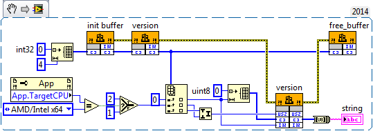
I have a DLL that has been written in C++, and the typedef in C++ code is defined as:
CY_BUFFER
Definition
typedef struct
{
int size;
char * data;
} CY_BUFFER;There is a function that should return the number of version as shown below:
C function
Version CY_INT (CY_BUFFER * buffer);A sample of code C to write to call the DLL is listed here:
Example in C
#include "cy_runtime.h".
const int CUDA_DEVICE = 0;
If (Initialize (CUDA_DEVICE)! = CY_SUCCESS)
Returns - 1;
Buffer CY_BUFFER;
If (init_buffer(&buffer)! = CY_SUCCESS)
Returns - 1;
If (version (& buffer)! = CY_SUCCESS)
Returns - 1;
If (free_buffer(&buffer)! = CY_SUCCESS)
Returns - 1;I have built wrapper LabVIEW using the DLL import wizard, but may not know what I have to do. I read the pointers to C/C++ dll dereferenciant in LabVIEW, but I do not understand how to use. Y at - it someone who can point me in the right direction here. I can't edit the C++ DLL, but I don't know in theory, only the types of data, I just may not know what the wizard trying to do when he created the GetValueByPointer VI code it generates automatically. If its C++, do I need to not use the wizard at all and create from scratch? Any help would be appreciated gratefully.
In addition to what Nathan said, you probably have an alignment problem. C compilers tend to align the elements in a struct to their inherent normal size. This means that the char pointer will be aligned to 4 bytes when you use LabVIEW 32 bits and bytes 8 when you use LabVIEW 64 bit. Now since the DLL also provides the init both the free function, this makes things a little easier. You can simply create an array of 4 integers from 32-bit bytes, pass it as a pointer to array to the function init() and version() free() and the only thing you need to do before release called an additional function of MoveBlock() where you adjust the offset in this table for the number of bits of LabVIEW.
This involves a number of things:
(1) your struct is indeed using 8-byte alignment, which causes the pointer to the byte offset 4 in for 32-bit LabVIEW and structure at byte offset 8 for 64-bit LabVIEW. Are you of any changes by using 64-bit LabVIEW, now that you have these 4 additional elements of the cluster between the size and the pointer?
(2) in fact, the size in the struct element specifies how much data is in the buffer tank.
And for the functions of the DLL error handling was completely omitted. To match the C code, you have shown that you should always check the function returns the value too before continuing.
-
I have a question about a FPGA project I'm developing.
I use a digital RIO NI PCI-7813R, objective and Module FPGA 8.6.1
I implement a SPI bus, master.
I use a state machine in a single loop of Timed Cycle. (about model on one of your examples IP)
I'm running the loop at 20 MHz, which produced a clock of 10 MHz SPI bus data.
I send you the data in 8-bit bytes delivered by a FIFO of the host.
Similarly, I return data bytes of 8 bits of the host by using a different FIFO.
I have no problem sending data, generate all the select chip and data impulses on my desired clock edges.
It's manual clean and perfect as seen on a scope / Logic Analyzer.When I read data from i/o pin however I have found unexplained behavior.
It is this: the data seem to be trolling by two read operations.
When I read the axis of I/O data to the specified limit of the clock that I generate.
I found that the data were two bits shifted to the right, i.e., deferred, one on the scope / Logic Analyzer.
I did a work around by two pins I/O multiple read operations in time of the gap between the data bytes.
There are no generated clock signal and no data valid on the I/O pin at the time of these two read operations as testified to by the scope.
And now the data received matches perfectly to the one sent.
I can only assume that there is some kind of pipeline or delay inherent in the IO read operations. (at higher clock rates)I suspect that there may be something in the optimization performed in the compilation of the structure of the SCTL the cause.
I had found it, sometime before in my development, that data has been little offset from 1 only one position.
I think it was at a slower pace of global clock.I also ran the same state machine in a classic logic expect everything in a loop with an FPGA, to produce a much slower system
and I found that there is no delay at all.I don't see anything in the configuration i/o pins that can affect this. (I turned off arbitration)
Similarly, I don't see anything in the documentation that could refer to this behavior.
8.6.1 of LabVIEW FPGA Module Known Issues (http://digital.ni.com/public.nsf/allkb/F6B5DAFBC1A8A22D8625752F00611AFF)I'm about to use and deploy the code with the solution because it seems to be reliable.
But I am at a loss to explain (in my documentation of the code) why it is necessary
or how to solve this problem if the compiler changes.
Do you have any suggestions?I think that what you run is that the number of sync records used with the digital I/o. If you right-click on the I/O item in the project and select the property page, you should see an option for number of registers for output and output enable synchronization. These settings are global settings for this I/O item that will be the effect on all nodes of the I/O writes to this point of I/O. Similarly, if you right click on the e/s on the schema node and select Properties, you should see a setting for number of registers of synchronization for playback. This setting is specific to this instance of the node for this element of I/O and can be configured differently for each node in the diagram. The effect is that each sychnronization registry will delay this beating of a clock signal. These records are inserted to prevent the problems of metastability and ensure that you always have signal levels valid when the IO is sampled on the edge of the clock. There is a problem whenever the producer and the consumer of the signal are market off different clocks, or at different clock rates. If the external device drive your digital inputs work synchronous clock you are producing, you can eliminate the registers of the synchronization. However, you must perform an analysis of delays in propagation of the signal between the two devices and make sure that all the settings and hold times are always met before. In the end, I think that the easiest and most robust solution will be to compensate for delays in sync in your code as you do already. I hope this helps clarify things.
-
Join the digital with numbers join function
Hello! a small matter of a guy who does not use labview for awhile!
I need to use the join number function to join two number DBL A and B to form a new number of A.B, like numbers of join function
in the example, I would like the results after the number of join function to 1.5
However, I understand that the function merge bytes/words and the result is far from what I expect... the means for
A and B are extracted from the command "READ" modbus register and are unsigned 16-bit
sounds easy enough, but I need a good refresher on how these bits, bytes and digital works together... DOH!
Thanks for all those involved, Bravo to all labview champions!
Hi yan.
as your description is not yet clear in all the details I provide two options, see one that fits your needs:

-
Send UDP traffic for bandwidth test
Hello
I am fairly new to Labview and eager to learn more. I currently do some tests on our devices in network bandwidth. For the moment, I use the open source Iperf to send UDP traffic to the device. I wanted to do the same thing with Labview. All I need is to send a UDP traffic to different bandwidth to the device. I watched sender example VI in Labview and I don't see an option to set the bandwidth. Say for example, I would send 20 MB/s of device. Can you please help a beginner?
Thank you.
wythat wrote:
Thanks Ben.
Understand that. Am I safe to assume that the data in the UDP wirte string is one byte per character?
Yes and keep in mind the network plug in bits per second not bytes.
I think the overhead of package (envelope with source destination Protocol and are control) are all part of the flow. I usually count as 10-bit byte "in the head" is estimated.
Ben
-
Map of CRC-16 TR - M Communication, Modbus RTU
I'm writing the procedure for generation of CRC - 16 for Communication if card - M from TECO Electric and Machining Company. Here's the algorithm that they provide to generate the word of CRC - 16 (attached is my attempt to implement, I look forward to suggestions). Here are verbatim:
A. load a 16-bit register with FFFFH. Call it the CRC register.
B. Exclusive or the first 8-bit byte of the message with the low byte of the CRC 16-bit registers, put the result in the register of the CRC.
Register to shift of c. CRC one bit to the right (towards the LSB), zero filling the MSB. Extract and examine the LSB.
D. If the LSB is 0, repeat the procedure C (another change). If LSB is 1, exclusive or the CRC register with the value of the polynomial A001H.
E. Repeat C, D, until the eight shifts were made. Wile to do this, a full byte will have been treated.
F. repeat the procedure B-E to the byte following the message so that all the bytes of the message is processed.
G. when the CHILD is placed in the message, TI upper and lower bytes are to be swapped.
If anyone understands this, please feel free to tell me where I would not (see attachment).
See you soon!
jmcbee,
I have attached a vi that comes with the Modbus LV library. You should get the answer.
Maybe you are looking for
-
How to change the date system Satellite Pro 4200?
HelloI need to change the date of my system and I didn't know how. I go into the BIOS and there is nothing to change the date. I have no operating system. I used to install Linux, but first I must change the date. Please can tell me how I can do? Sor
-
Critical error (BSOD) on Satellite A300-1MW
Hello. I have problem with critical error on Toshiba Satellite A300-1MW. My operating system is Windows Xp Pro SP2 with the installed drivers that are downloaded from the Toshiba site.This is the name of this error: STOP: 0X0000000A (0 X 0, 00000002
-
Center help and Support using the desktop icon
Office a700y Windows XP - pro. A new ' 05. Just tried to get thru to HP tech using the icon on the desktop for the help and support center. The only way to get thru is signon line through windows or msn. Try not to use a HP Application Recovery no ch
-
Wow Error 132 memory cannot be written... and so on
I'll have wow Error 132 arrive about an hour after the start of the game world warcraft, the game crashes and the error 132. I went on the support site for games and have done everything they said to do to solve the problem, I even updated my drivers
-
HP Deskjet Ink Advantage 2515: HP Deskjet Ink Advantage 2515 no printing, scanning or copying
Hello I own a printer and it never gave me problems, so far. It is not scanning, copying or printing! When I try you are ordering from the office, standing documents in the queue in the "Active printers', and he said only:"printing"in the first docum