No generated impulses!
Hey!
I'm unable to generate a PWM signal with a channel of counter on our map of NOR-6733.
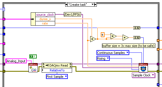
I use DAQmx screw for: create a task (frequency = 50 Hz, duty cycle = 0.07) - set the task to samples with a certain number of samples - start the task - wait until they were written - stop the task (is that really necessary?) and delete the task.
I check the result with an oscilloscope. If I run the VI, the pulse train only a few times is generated and sometimes nothing happens.
The same thing happens when I use MAX and create a train of pulses with the dialog "test panels.
It seems to me that there is a hardware problem, how I can study what is the problem?
Does anyone know this problem? Am I doing something well wrung out? Thanks for any help!
Best,
Steve
Hey once again!
It was my bad! The osci was slowing down. Once she was the acquisition of the signal when the puls was conducting his high State and the other time, he acquired the signal when the pulse had his low state...
See you soon!
Steve
Tags: NI Hardware
Similar Questions
-
Generate impulses to drive an instrument AND trigger some HAVE (the S Series DAQ)?
Hello
I use a PCI-6122 (with LV 7.1 and Windows XP). I'm generating a TTL pulse with one of the counters on the Board (from 0). I need to use this momentum to drive a shutter and also as a trigger for data acquisition (HAVE). Is there a way to "split" the output so I can receive TTL pulses to two simultaneous different terminals, for example to "CTR OUT 0 ' and"PFI 3"? If not, could you please explain to me, or direct me to the equipment, on the if (and how) I can synchronize the two counters in order to achieve the same thing?
Thank you.
Never mind... I figured out how to generate both synchronous impulses go both counters using a common trigger: I use a pulse generated from a digital lines (DO) that I'm physically routing to the CTR terminals 0 DOOR, i.e. PFI 9 and CTR 1 DOOR, i.e. PFI 4,. I am attaching a capture in case it is a help to someone on the other screen.
-
How to generate impulses for change of Boolean?
I need to generate short pulses during the change of Boolean from 0 to 1. This impulse is necessary to reset the counter.
I tried with the Structure of the event with the change of value, but I think I did something wrong.
Maybe sambody can give me some tips to make it otherwise?
Thank you in advance.
Concerning
Rogal wrote:
I need to generate short pulses during the change of Boolean from 0 to 1. This impulse is necessary to reset the counter.
I tried with the Structure of the event with the change of value, but I think I did something wrong.
Maybe sambody can give me some tips to make it otherwise?
Thank you in advance.
Concerning
We assume you want a pulse when clicked on a button on front of (boolean).
I don't always know just what he's wanted.
You want a single pulse when x is greater than 4?
You don't need a structure for this event.
-
I want to program a VI that generates the pulse train. So, I looked for examples and found one as below, also as an attachment. Now, I want to see the pulses generated by this example by adding graphics of waveform in the example. Can someone show me how to do?
Thank you
Jay
You can't see the waveform within the VI, which generates pulses,
You must acquire signals using another channel of acquisition and acquisition
-
the use of two meters: one for the generation of regenerable impulses, one as a counter
I'm new on use the counters. I use an NI PCI-6110 multifunction data acquisition card. I want to count a digital input (on the connector of the PFI 2) pulse and also using the entrance to trigger another counter to generate impulses. So I configured the first counter (task 1) to generate digital pulses with PFI2 as a source of relaxation and redeclenchables award; and set up the other counter (task 2) to count the number of edges of the digital signal with.... But after the two tasks began, the first task was an error 50103 (or the possible reasons: NI Platform Services: the specified resource is reserved.) The operation could not be performed as indicated.) The block diagram is attached. Thank you.
Your Board uses very-old-in-electronic-standards-DAQ - STC a smart meter that requires a little secretly * two * counters work together to make a finite pulse train. He is not actually secret if you read the right parts to the right documentation, but it's not hard to miss if you are unsure you should look. It has been a while since I've done a lot with these counters, but I have this nagging thought that they may not support redeclenchables finishes pulse train generation at all. I would caution you to at least check this.
In any case, it is the reason for the error. The finite impulse generation task uses only the counter that you specify, but there was also this one to help. A couple of new generations of smart meter (NOR-TIO, DAQ-STC2) continues to have this limitation, but the * more * recent it is no longer made.
X series boards use the chip "NOR-STC3" that give you 4 programmable counters by the user instead of 2 * AND * everyone can generate pulse trains finish without using a help desk. You may want a pair of them upward with your 6110, assuming that you need simultaneous sampling analog 6110's capabilities.
-Kevin P
-
How to generate a PCLK at the exit of a 1409?
Using a 1409, I need to generate a 13 MHz PCLK to send to a camera. Use one of the IMAQ generate impulses screws? It does not resemble a way very simple to simply enable a continuous clock output. I can't find any other VI which looks like a possibility.
Thank you
Brad
Hello Brad,
You should be able to output a signal on your PCLK line by adding the following lines to your file to camera.
Attribute (external clock) {}
{Value (list)
{Name (off)
Action (clock) {}
Frequency (0)
}
}{Name (on)}
Attribute (clock frequency) {}
{Value (integer)
Min (50)
Max (20000)
Increment (1)
{Display
Offset (0)
Multiplier (0.001)
Precision (3)
Units (MHz)
}Default (5000)
Current (5000)
Action (clock) {}
FloatValueFrequency
}
}
}
}Default (Off)
Current (power off)
}
}I would like to know how it works.
-
Acquisition of Digital Data Output: generate a pulse with a specific width (depending on time)
How can I generate a digital pulse with a specific width? I was not able to find examples online. Thank you!
With the USB-6000 - essentially none. He has only digital software programmed according to i/o. on your system, you may be able to generate impulses at speeds up to a few hundred Hertz, but there will be a considerable amount of timing jitter. Tens of milliseconds can be common and even longer variations may occur occasionally.
Please indicate which are the times for your impulses, so someone may be able to provide recommendations specific to your needs.
Lynn
-
How to generate a pulse signal?
Hello
I'm relatively new to LabVIEW and I need to generate an impulse (Dirac function) in the motor continuous. At the same time, I need to be able to change the pulse width.
I am currently using LabVIEW 7.1.
Hey,.
With your E-Series cards, you can counter to generate impulses for the user.
The best way to find examples using the Finder example under the Help menu of LabVIEW. Simply navigate to the e/s material > DAQmx > Counter > generate signals or search for pulse generation.
-
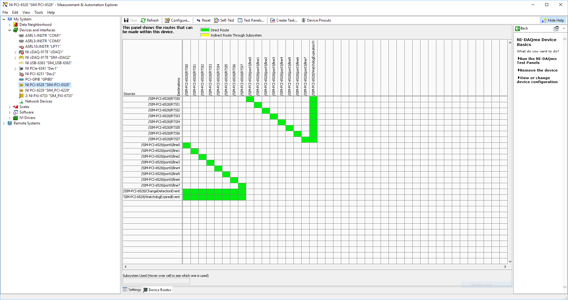
Using SMU 6612 to measure PXI-6528 pulsewidth channel - channel is not available.
Hi all
I use SMU 6612 card counter to measure the pulse width of the signals to PXI 6528 DIO card. These two cards are in the same chassis PXI (NI-SMU-1065). I could measure the pulse widths using the example LabVIEW 2013 Counter - pulse width of reading and (over) frequency example of .vi. However not all channels of the PXI-6528 map appear in the drop-down list of channels on the pulse width can be measured. Try to connect any other channel that those which are available in the drop-down list returns the error. On the PXI card port 6528 0,1 and 2 are entered ports and port 3-5 are output ports. I can measure the pulse on port 0, 3 width and line 0 port 1 and 4.
Can someone explain to me why don't see port 1 or port 2 channels in the drop-down list or force the VI to measure the width of pulse on these channels?
I can plug PXI-6528 external input channels SMU 6612 counter input channels and measure the pulse width, but if possible I'd like to avoid the external wiring between the 2 cards.
Probably not. Unless the routing plan is in fact reversed as it seems a bit sorta that. As stated on my system, you can route * of * a port of entry * to * RTSI, or you can route * of * RTSI * to * one output port. This does not make much sense to me, but that's what I see:
If the routing card * is * reversed, your only likely workaround without physical wire would be to generate impulses in question of port 3. It's pretty clear that 1,2,4,5-tetrachlorobenzene ports have no ability to interact with the bus timing, physical wiring would be the only option.
-Kevin P
-
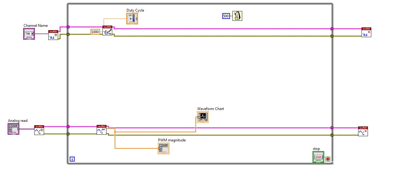
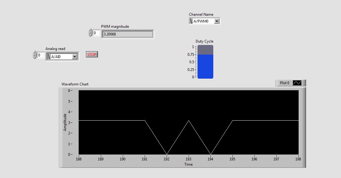
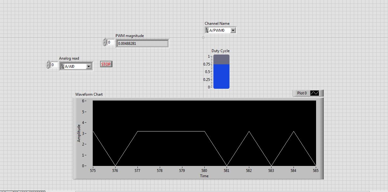
Problem in reading the PWM signals in myRIO 1900
Hi guys,.
I work with myRIO to generate PWM pulses.
Here is the block diagram of my circuit.
I connected external to the analog input pin PWM pin. So I can watch the PWM pulse in the waveform table.
But the waveform is not clear. This is as shown in the screenshot.
See that the waveform is not correct. When I'm watching the same PWM pulses in the CRO (cathode ray Oscilloscope, oscilloscope real in the real world), I get exactly the waveform. that is, the PWM pulses are generated correctly. But the analog read is unable to read the PWM pulses.
I faced the same problem with the pin of analog reading earlier when I read the input voltage. Is not give continuous reading of the voltage input.
Please guide me how to read these impulses via analog read.
Please tell me at what frequency range, I can use this myRIO to generate impulses?
I am able to use 40 kHz?
Hi rcs.
The desired pulse frequency is 10 KHz. My sampling rate must therefore 100 kHz, which is not possible in data acquisition mode. There is another problem with the myRIO. Only AI0, BI0 and CI0 has n-sample mode. The analog input pins is still have no n-sample mode. But in my project, I need 4 pins of I in n-sample mode, which is not possible. In addition, the sampling rate should also be favourable, which does not happen in my case. We can say that this is a disadvantage of myRIO with data acquisition mode.
The only alternative to solve this problem is to use FPGA in myRIO.
He can taste a 25nS rate.
But little complexity is there -
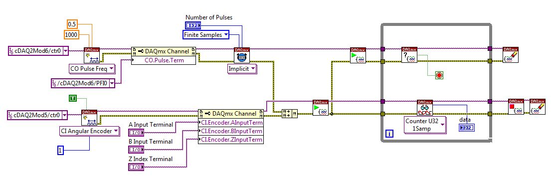
Stepper motor control while reading encoder
Hello
I'm looking to generater a pulse train to control a parallel reading and step by step motor in the impulses of the encoder of the motor. I was able to create two distinct VI who perform these taks individually, but when I put them into a single program (as shown below) is where I run on resource issues. I think I'll have problems affecting timers my properly and that's why I'm having these problems. I use a NI 9401 to generate impulses for the controller and a 9402 train OR read in the impulses of the encoder. If possible I would bring up just using the NI 9401 for the inputs and outputs if possible. The two are connected on a backplane cDAQ 9172 NU. Any help or suggestions would be greatly appreciated on what I'm doing wrong.
Thanks for the suggestion of Carmen, but I was able to understand what it was with a little help from NEITHER. The finite number of pulses of timing function requires 2 counters, so when I tried to read in the encoder data there where no meter more left on the backplane. Changing impulses continuously solved my problem. I'll take a background of most recent basket with 4 meters from the lab which should allow me to run the finite number of pulses and read data from encoder at the same time.
Thanks again,
Doug
-
Need help with counters on PCI-6221 (37-pin)
Hi all
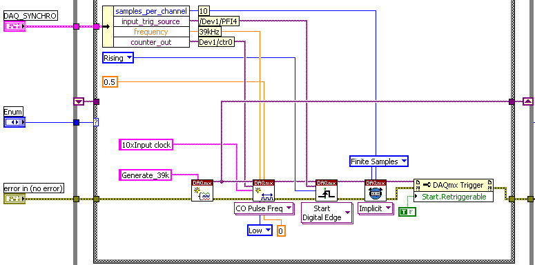
I have a system with a PCIe 1429 connected to a Basler A504 camera and one I use a clock generator (SRS CG635) of 3.9 kHz for trig the image acquisition.
On the same system that I need to add a PCI 6221 37
PIN to acquire:-2 HAVE 39 kHz, synchronized with the acquisition of the image. (Sample of the 10 for each image)
-1 meter to measure a frequency
The accuracy of my clock of 3.9 kHz being much higher than what I have on the DAQ card, I thought that an interesting option would be to have a redeclenchables DAQmx task that generates impulses from 10 to 39 kHz for each pulse received from the clock and then use it to trigger the DAQmx AI task.
Of course this can only work if the 'trigger' sources that I defined for these two tasks do not take both counters that I have on the card.
So, let's describe the DAQmx tasks:
-Here is the one who generates the 39 kHz on 0, the counter of the 3.9 kHz I entered as a source on PFI 4 trig
-This is the task of analog input for which I put the trigger on 6 PFI.
It is: I have "softwarely" know the jury to deliver output (Ctr0) 6 FBP counter? And if so, how?
Thanks in advance for any help!
Maybe you missed something that I didn't really point out in my post. The method I described would use the external clock of 3.9 kHz precise as a sample clock, so you would * not * be in danger of loss of synchronization in 1 s per day. You need to only son of this clock signal in a stem of PFI available and configure the task to HAVE it as a result. The 80 + kHz clock that controls conversions within each sample cycle * would * be generated by the jury of 6221, but he don't would not accumulate any out-of-sync error because he gets "retriggered" on each edge of the 3.9 kHz precise clock.
-Kevin P
-
Using a counter with FiniteSamps and one with ContSamps
I am using 2 counters on the NI USB-6229 (or USB-6259), case where a counter is implemented for FiniteSamps and another for ContSamps. I have the following MeasurementStudio code:
ErrChk DAQmxCreateCOPulseChanTicks(hCnt0, "Dev1/ctr0", "", "20MHzTimebase", DAQmx_Val_Low, 0, 400, 400);
ErrChk DAQmxCfgImplicitTiming(hCnt0, DAQmx_Val_FiniteSamps, 100);ErrChk DAQmxStartTask (hCnt0);
ErrChk DAQmxCreateCOPulseChanTicks(hCnt1, "Dev1/ctr1", "", "20MHzTimebase", DAQmx_Val_Low, 0, 400, 400);
ErrChk DAQmxCfgImplicitTiming(hCnt1, DAQmx_Val_ContSamps, 2);
ErrChk DAQmxStartTask (hCnt1);
When I run it, I get an error-50103 "the resource specified is reserved". If I change the FiniteSamps to ContSamps on the first counter, everything works fine.
If I use only one counter with FiniteSamps, everything works very well.
Is this a bug in DAQmx or the use of double counter on M Series devices is limited to ContSamps?
VIC
Hey Vic,
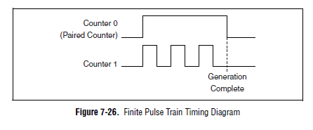
It is actually planned on a device of the M series. Here's a time diagram of the M Series user manual which might make this a little clearer:
The device uses actually one counter for the other door so the result is a generation of finite pulse. If you can provide the door from another source, you can configure a generation of continuous pulses on two counters and their door (DAQmx calls it a "relaxing break") of this external signal.
You can also look at the use of the digital I/o correlated to generate impulses over multiple (up to 32 lines on your 6229 and 6259). You could use one of the counters to generate a time base for digital lines and build the waveform as a result.
One thing to note is that our new X series cards can generate a generation of impulses finished on a "single" counter (it was actually a paired internal counter that allows this). There are four accessible counters by the user on the X series devices, which means you could generate four pulse trains finished.
Best regards
John
-
NOR-FGEN Arb Express reactivity
Hello
I'm playing with the VI Express NOR ANY Arb (with the NI PXI-5421) in order to learn how to create my own VI to generate impulses of the arbitrary. However, I find that when I click on "Run" in the Express window, my o-scope seems never to receive the waveform correctly. I use the sine wave sample and when I click on 'Run' with him put "Start continuous" the o-scope screen updates a few seconds later with a fragment of a sine wave, and it does not always up-to-date. The Test panels for the 5421 work very well with the o-scope, so I don't know what goes wrong.
Any help is appreciated.
Thank you
Billy MaierEDIT: Never mind, the problem itself. I don't know how to remove the wires.
Glad to hear that you have found an answer to your probem a little extra tip is to go beyond the express VIs as quickly as possible. The simplified interface they provide comes at a price. Banely, these screws will be nake laying of assumptions that do not always work in your favor.
Mike...
-
Continued use of digital dashboard to stop a generation pulse train
Hello
I need to generate a train of pulses for a period of time. However, this period is variable, and because of that I can't
Use the finite number of samples.
The pulse train must be output depending on the State of the digital I/o. When the line output goes high, must be output of the pulse train.
and when he goes down the pulse train should be stopped.
I use a USB-6212, but is already using one of the available counters for the measurement of pulse width. I tried to do a
AND logic with the pulse train and line activate, but due to the execution time of vi this solution modifies the pulse train
frequency, which is not acceptable.
Thanks in advance,
Mariana.
Hi Marianne,.
Your previous message mentioned "line in/out" (in the singular) and "enable line" (in the singular), isn't "the i/o lines" (in the plural). Are the two edges on the same line in/out? Or are they on separate i/o lines (for example, climbing on PFI0, falling on PFI1)? Can you clarify your needs?
If the fronts and sides come from the same line of output, then a relaxing break seems to do what you want: cause the meter generate impulses while the input/output line is high and cause the meter to stop while the input/output line is low. However, if you start the job, while the input/output line is high, it will immediately start out impulses. If you want to wait the first front line input/output to generate impulses, you can use a trigger 'start of arms' (which is just below "break" in the node property). When the trigger 'arms beginning' arrives, the meter will be armed, and therefore, the task uses the break to determine when to generate impulses. Using pause and start the same counter task returns error-200146, "put in Pause and start triggers cannot be active in this task," but using break and triggers 'arms beginning' in the same task of counter should be correct.
If you want to increase the edges of PFI0 to start the meter and the fall of the edges of PFI1 to stop the meter, which is more complicated and it will take thought additional (and possibly additional hardware).
Brad
Maybe you are looking for
-
Firefox has my bad location - how to fix this?
Firefox thinks I am located in Poland (I'm actually in the United Kingdom) and share this information with other sites, so all the ads I see for example. on Youtube are in Polish, and when I type a search in the search bar, I'm redirected to google.p
-
28.0 Firefox indicates that my installed Java SE 7 U51 is vulnerable (2014 03 20)
When I use: 'tools-> Add-ons-> Plugins' and select "Check to see if the plugins are up to date", Firefox 28.0 (said currently the last updated version) means that the detected Java version (currently Java (TM) Platform SE 7 U51) 'Vulnérable' is and s
-
Satellite Pro L300-11n: questions realtek RTL8187B wireless adapter
my wireless is down from time to time and im speeds do not get very good download. is the realtek card right? as im trying to get new drivers for it as I tried to update via the Device Manager and he said he was aware, but I can't see why her act lik
-
Most of my OE .dbx files are disproportionately high
Most of my OE .dbx files are disproportionately high. For example a file has only about 100 messages small (IE without attachments) in it, and yet it is a gigabyte in size. How can I make the "right" size folder? I tried compact all folders, but that
-
I have two hard drives (C: and E :) on my computer. E: has been used as a backup. I now use an external HD for backup. When I re-formatted E: it shows the disc to be full when I check its properties. When I try to open Explorer or e: a window opens s