Omega flow meter sensor daq connection
Hi all
I have sensor Omega FTB 1302 and NI DAQ 6229. Sensor has analog output. I do not know how to connect these sensor and daq.please help
Tags: NI Software
Similar Questions
-
conversion of turbine flow meter
Hello
My apologies for the query, but this software is all new to me. I have a cDaq-9188 8 medium chassis containing several modules including 2 off 9401 counter modules, I run signal express version 6.0.0.
My problem is that I have 3 miniature flowmeters turbine (GEMS units FT-110 series) which give various pulse widths depending on what is the 5V square waves. I brought to the entrance of my 9401 and look of good signals so guess that's my express configuration signal which is the cause of the problem,
I connected the + ve and gnd outputs of the flowmeters Com, DIO1 + Com and DIO3, DIO0 + Com on one of my 9401 cards.
I can see the increment in the number of pulses on measurement & automation Explorer when I run test for this module Panel and watch the chefs of edge that my system can see the pulse from trains.
When configuring the express signal I need it to read in l/min, 58-575Hz corresponds to 0.5 to 5 l/min, but I can't seem to convert the pulse in l/min.
If I select DAQmx acquire > counter entry > frequency it gives me the possibility of updated the custom scale, but every time that I run it I get the error signalling DAQ assistant upward. I tried many synchronization settings with no luck. The only time where I have this power as successfully is using counter entry > County of edge, but I'm stuck on how to convert l/min as it has no function of scale (I know!)
Any help appreciated.
I think that he is referring to l/min in litres per minute, and I guess the Freq of flow are the values of this compilation on the scale.
If this is the case; Carl, it seems to me you must configure a custom scale. You can do it in the channel settings tab in the DAQmxAcquire stage. Under custom scale select Create new, and then select map scale. Min/max Freq should match your flow min/max.I have attached a few screenshots for reference.
Let us know if we are on the right track, otherwise we might need more information; FOR EXAMPLE. file seproj and a bit more info on the flow meter (type of connection, the output signal, etc.).
In addition, a brief look at the documentation on this flow meter recommends the use of a pull-up resistance. Might want to look there as well. -
How to connect an International ST75 components fluid flow meter to the DAQ system?
Hello
I am trying wire a ST75 meter to my DAQ system consisting of a device PCI 6052E DAQ, SCXI 1102 b card and a block to connect SCXI-1300. 1102 b has four 249 Ohm resistors connected to channels 0-3 for use with the current of the flow meter signals.
The flow meter has two output signals 4-20 my and RTN, SINK, SOURCE and com connections The documentation is not clear how to connect the sensor to the Terminal Board, other than to say if the two output signals is used, one of the sons of RTN are used. So far, I can not get the signal from the flow meter to work in LabView, so I don't know if I have it plugged properly. Currently I have 1 wire OUTPUT on the Terminal Board + CH2, CH2 - wire to the chassis ground terminal and the COM lead on the sensor.
Thanks in advance.
Towards the end of the manual there are wiring diagrams:
SINK/SOURCE/COM are used for pulse ouptuts. It seems that there are two outputs, one for 4-20mA temperature the other for flow.
The one you need (flow) conjnction with RTN wired to use the + and - (or COM) your DAQ hardware.
-AK2DM
-
Magnetic sensor to the top of analog frequency AC for Turbine flow meter measurement
Hello!!
I use the following hardware configuration to measure a flow meter flow turbine.
Material: 1000 SCXI Chassis
SCXI 1102 voltage input module
SCXI-1303 terminal connection block
Flowmeter: output signal is the frequency of the alternating current (30mv peak-to-peak). Sensor is a magnetic sensor type.
I tried to convert the signal of output voltage in the area of frequency using the FFT, but I get the wrong data.
I wonder if anyone can suggest good troubleshooting techniques so that I can understand what is mess up my position or my technique of measurement in labview itself will not completely? (From my understanding I think that I can measure the frequency of the ac voltage signal generated by the sensor of the FFT. By measuring the frequency I can calculate the water flow)
I am aware that a potential cause might be the ground loop in the system. The signal is based solely on the SCXI-1102 with factory default bias and pullup resistior network. I see no other reason reading wrong or fault in my measurment. Also the flowmter is brand new and there is no risk of damage to the sensor.
I'm sorry if I'm missing out on any important detail to answer that I am relatively new on the techniques of data acquisition.
Thank you
Concerning
Aditya
It's conditioning of signals... and that's what you want to do, so it's not so far

And if your signal about 30mV Ridge to Ridge, it fits perfectly in the beach of crete to 200mV Ridge... I wouldn't say no need of amplification... the + 100mV is not a minimum of signal, this is the maximum signal in this range
Hang it up, take a measurement in single channel mode with one all 10kSPS sample rate take 100ms (1000points) and feed in single tone detection...
display with a graph of signal, stop the vi, in the rigth diagram, click the graph icon and create a constant, save that in a vi and post here if you need help in signal processing
-
How to connect a magnetic flow meter to a 9203 module?
Hello
I have a magnetic flow meter, which gives me a measured 4-20mA signal. I'm reading this signal using the 9203 module. As he wrote in the technical data I have to use external power supply. I have 2 sons of my August flowmeter + and GND. I connect August + food + and GND to AI0 after that - from feeding to Com in 9203. I am doing everything correctly? I see not all values change.
Thanks for any help.
Hi Rodzynek,
Have you tried looking at the output with only a voltmeter digital or similar on the output?
It would be a good guide to tell you what really is the signal.
The 9203 gives a FXP signal in amperes, so if you expect 8ma your jpg shows 7.16 to 7,74 my which is close.
As I said earlier, I found that the signal of the 9203 is rather noisy and apply filtering to clean up the signal, I guess thatâs you measure the flow rate of the signal change very quickly compared to the sampling frequency 9203.
Also check if the WHAT GND is connected to the MASS of other output signals.
See you soon
Stephen
-
Help explain the flow meter VI
After a lot of tinkering, I seem to have developed an effective VI for use with a type/pelton turbine flowmeter. The flow meter outputs a stream of pulses which
can count on the counter of my 6501 line. Unfortunately this eureka moment happened somewhat by chance, and I'm hoping someone
could be kind enough to explain step by step or in terms very simple for beginners (me) works of VI, thank you.
Kind regards
GER
GER,
Welcome to the Forums and LabVIEW.
If you don't the have already made, please work through the tutorials online to get started with LabVIEW. The answers to some of the questions you may have are probably there.
A brief description of your VI:
1. the overall structure is a loop For. It works for the number of iterations that is connected to the Terminal in your case 5 N.
2. the calendar of the loop is determined by the longest time required for any part of the code inside the loop execution. On the first iteration, the DAQ Assistant configures the counter and starts measurement. On all subsequent iterations, he reads everything simply an indictment. On these iterations, the 25 les 25 ms ms expect will dominate. This VI runs approximately 40 iterations per second (for 5 iterations).
This means that the program will take place on 5 * 25 ms = 0.125 sec and then stops. If you run for more 1/8 of a second to help run it continuously button, STOP. Which is intended for certain types of troubleshooting only.
3. the table of waveform and the flow rate meter only shows the last value of the five iterations. (This suggests also that you use run continuously)
4. the registers at offset in this VI nothing do. The upper shift register calculates the cumulative number of the flow meter, but the result is never used. The underpass registry has nothing connected to the Terminal inside the loop on the left. It could be replaced by a terminal.
Suggestions:
1. in order to avoid using run continuously, replace the loop with a while for loop. Add a stop button on the front panel and connect it to the stop it real terminal in the loop. Move the graphic terminals of waveform and flow inside the loop.
2 check your pulse to the algorithm of flow rate. The time for the count interval must be considered. For example if the meter registers 25 pulse in 25 Member States, which represents 1 000 pulses per second. This isn't which will show your VI.
3. see examples of code that uses counters.
Lynn
-
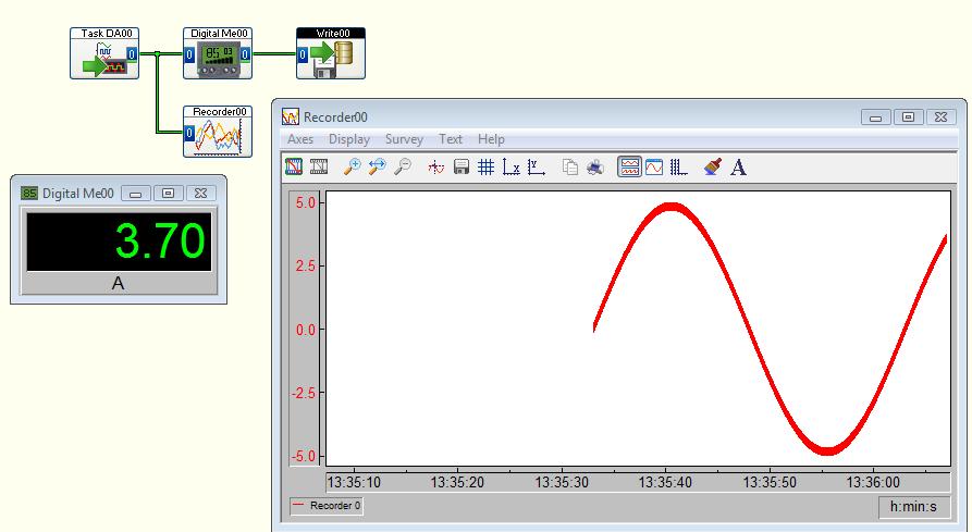
Digital meter as ammeter connection
I'm new to DASYLab and I'm trying to connect a digital meter module to display current measured by a NI 9227 current DAQ. I copy the entries on the exits of the meter and then treat the meter as being in the current path? In addition, connect the current DAQ in the path that I expect that it is electrically with a release?
Don't know exactly what you're asking.
Here's what I'd do from step 0:
Step 0: create a task NEITHER-DAQmx in MAX (Measurement & Automation). Configure it to CONTINUOUS sampling and the value of the samples read to be about 1/10th of the sampling frequency. For example, it the sampling frequency is 25K (Hz), and then configure the samples to read 2500.
Save and run the task to test. Stop the task. Close the MAX.
Step 1: DASYLab open and create the analog inputs of NOR-DAQmx. Configure the following task that you created.
Step 2: Create a digital meter module. Connect the output of the analog input to the input of the meter.
That's all.
If you add more logic, you can configure the DMM to 'copy the entries' and connect your logic to the digital counter, or you can PLUG the wire between the analog input and counter to connect to other modules.
Logically, it is the same thing. The output of the meter is simpy the same data that are placed in the entrance of the meter. He is not treated or changed somehow by the meter.
I've set up as a simulated device, and it's what might look like a spreadsheet.
-
Flow 11: Losing WiFi connection keep local
Several times now that I lost internet connection but I am able to keep the local connection. Yellow triangle on WiFi States report icon that I lost the internet connection part. I run network troubleshooting and it asserts its reset wireless but not my internet connection returns. Only after I have turn off the WiFi and turn it back on my internet connection is avaialable. I ran HP support and have all driver updates and Windows updates.
So far, none of my other devices meet this problem. I know that this notebook has a Realtek wireless card which I know is not the highest reliability. Realtek and come back to me of many laptops with connection problems. It's like they work only when they feel like it. Guess that this flow probably has a WiFi card soldered to the motherboard. So I guess that replacement that's out of the question. Hope someone has some other ideals or Windows 8.1 may be to blame?
After doing more digging I found several others user the same WiFi card with similar problems. A person went up to say that it is a problem of firmware on the chip and others say a Windows 8.1 questions that they were working to solve.
In any case, I go a day without problem and use my 11 stream a lot for business. So I guess that the question does not affect me so much.
-
Duty slot in my sensor signal connection related problem class.
I fanned simple class based on the NDK documentation found here - http://developer.blackberry.com/native/documentation/cascades/device_comm/sensors/
But in my case signals do not plug on slots and returns always false. I was just wondering what I did wrong? Looks all logical.
Here's the class:
#include
#include "Sensors.h"

Sensors::Sensors(QObject *parent) : QObject(parent) {
    // Create the compass sensor.
    m_CompassSensor = new QCompass(this);
    m_Accelerometer = new QAccelerometer(this);

    // Set the orientation mode to fixed so that sensor readings
    // aren't affected by device orientation.
    //m_CompassSensor->setAxesOrientationMode(QCompass::FixedOrientation);

    // If any Q_ASSERT statement(s) indicate that the slot failed
    // to connect to the signal, make sure you know exactly why this
    // has happened. This is not normal, and will cause your app
    // to stop working
    bool res = connect(m_Accelerometer,
                       SIGNAL(readingChanged()),
                       this,
                       SLOT(accelReadingChanged()));

    res = connect(m_CompassSensor,
                       SIGNAL(readingChanged()),
                       this,
                       SLOT(compassReadingChanged()));
    Q_ASSERT(res);

    // Since the variable is not used in the app, this is
    // added to avoid a compiler warning.
    Q_UNUSED(res);

    m_CompassSensor->start();
}

Sensors::~Sensors() {
    m_CompassSensor->stop();
}

void Sensors::compassReadingChanged()
{
    QCompassReading *reading = m_CompassSensor->reading();
    qreal azimuth = reading->azimuth();
    qDebug() << "The azimuth is " << azimuth << " degrees.";
}

void Sensors::accelReadingChanged()
{
    QAccelerometerReading *reading = m_Accelerometer->reading();
    qreal x = reading->x();
    qreal y = reading->y();
    qreal z = reading->z();

    // For debugging purposes
    qDebug() << "x acceleration: " << x;
    qDebug() << "y acceleration: " << y;
    qDebug() << "z acceleration: " << z;
}
Here is the header
/*
 * Sensors.h
 *
 *  Created on: 2014-02-01
 *      Author: misha
 */

#ifndef SENSORS_H_
#define SENSORS_H_

#include
#include
#include
#include
#include

using namespace QtMobility;

class Sensors : public QObject{
public:
    Sensors(QObject *parent = 0);
    virtual ~Sensors();

private:
    QCompass *m_CompassSensor;
    QAccelerometer *m_Accelerometer;
public slots:
    void compassReadingChanged();
    void accelReadingChanged();
};

#endif /* SENSORS_H_ */
Please advise! I was fighting with this for a few days already... I bet I missed something important but s mall

Thank you
Hello! Q_OBJECT macro is missing from the top of the class declaration:
class Sensors : public QObject{  Q_OBJECT
public:
  Sensors(QObject *parent = 0);
p.s. This line changes, the first could not connect will not be detected. It should probably be & =
res = connect(m_CompassSensor,
-
Looking for the flow meter liquid sensiron VI
Can someone direct me to a VI for a liquid of Sensiron meter? I use a DSM of 1600-20
Thank you
Thanks to the folks at Stanford and the University of Santa Clara, it works now, I'll join the vi
-
HP SimplePass - error "sensor not connected.
I have used successfully to my software and sensor SimplePass fingerprint for a year, but he has now suddenly stopped working. A friend of my son was using my laptop and may have changed some settings in the error. Now, when I go to the control panel and select biometric devices, he bed 'Windows don't think biometric devices on this computer. You will need to attach your device or install device drivers. I lookd in other forums and that you have downloaded the new drivers Validity Sensor and SimplePass software update, but it disappeared again. Aside from never lend my cell phone once again, any suggestions would be appreciated!
Hey,ife1973.
I see that you have a simple problem with pass. Looks like something was wrong with the drivers or the installation itself.
I suggest you get the simple pass and the fingerprint driver.
Follow this document which will guide you on how to open the Recovery Manager.
Like this:

You want to recovery of the fingerprint driver, which should be called "Validity Sensor" and the program called 'Single Pass'.
To retrieve the 'single Pass', you can select "reinstalling software." Then to retrieve the fingerprint driver, you need to select 'Hardware driver reinstallation.
Retrieve the two programs.
Please let me know the results. If you have any other questions let me know.
THX
-
mass flow meter and controller
Hi all.
I have the mass flowmeter and controller of Bronkhost. I tried to control using RS232 communication and I found labview progrma developed by Bronhkost to set the desired value and read the measured values. These works of independent Labview programs and when I try to set and read the measured values by connecting one after the other. I can adjust the temperature setting to the controller, but I can't read the measured values. Therefore, I here enclose labview programs, developed by Bronkhost. Any body who has done it before please help me with my troubles.
Concerning
just solved!
-
on my laptop the meter does not read and he tells me that the driver is missing, but when I try to download on the site the hydrotechnik nothing happens
TeeGee
You should probably contact the meter manufacturer.
-
I've recently updated to 8.3.2 and I have been informed of these NAT changes, but even after reading the https://supportforums.cisco.com/docs/DOC-12569 I am still unable to rectify the communication network 192.168.100.0 VPN with hosts on 172.16.1.0 and 172.16.9.0. VPN clients connect to the external interface, and I try to ping inside and the demilitarized zone, respectable 172.16.1.0 and 172.16.9.0 hosts. VPN client shows that the two previously mentioned networks such as roads of security, but still not to the ping pong.
# sh nat
Manual NAT policies (Section 1)
1 (inside) to the (whole) source static obj - 172.16.9.0 obj - 172.16.9.0 destination static obj - obj - unidirectional 192.168.100.0 192.168.100.0
translate_hits = 0, untranslate_hits = 0
2 (inside) to the (whole) source static obj - 172.16.1.0 obj - 172.16.1.0 destination static obj - obj - unidirectional 192.168.100.0 192.168.100.0
translate_hits = 0, untranslate_hits = 0
3 (inside) to the (whole) source static obj - 172.16.1.0 obj - 172.16.1.0 destination static obj - 172.16.12.0 obj - one-way 172.16.12.0
translate_hits = 0, untranslate_hits = 0
4 (dmz) to (outside) source static obj - 172.16.9.0 obj - 172.16.9.0 destination static obj - obj - unidirectional 192.168.100.0 192.168.100.0
translate_hits = 0, untranslate_hits = 0
5 (dmz) to (outside) source static obj - 172.16.9.0 obj - 172.16.9.0 destination static obj - 172.16.12.0 obj - one-way 172.16.12.0
translate_hits = 0, untranslate_hits = 0
Auto NAT policies (Section 2)
1 (dmz), to the source (external) static obj - 172.16.9.5 interface tcp www www service
translate_hits = 0, untranslate_hits = 142
2 (dmz) (outdoor) source static obj - 172.16.9.5 - 01 interface service tcp 3389 3389
translate_hits = 0, untranslate_hits = 2
3 (dmz) (outdoor) source static obj - 172.16.9.5 - 02 interface tcp ldap ldap service
translate_hits = 0, untranslate_hits = 0
4 (dmz) (outdoor) source static obj interface - 172.16.9.5 - 03 service ftp ftp tcp
translate_hits = 0, untranslate_hits = 0
5 (dmz) to (outside) of the source static obj - 172.16.9.5 - 04 interface tcp smtp smtp service
translate_hits = 0, untranslate_hits = 267
6 (inside) source static obj - 172.16.9.0 172.16.9.0 (dmz)
translate_hits = 4070, untranslate_hits = 224
7 (inside) to (dmz) source static obj - 10.1.0.0 10.1.0.0
translate_hits = 0, untranslate_hits = 0
8 (inside) to (dmz) source static obj - 172.16.0.0 172.16.0.0
translate_hits = 152, untranslate_hits = 4082
9 (dmz) to dynamic interface of the obj - 172.16.9.0 - 01 source (outdoor)
translate_hits = 69, untranslate_hits = 0
10 (inside) to the obj_any interface dynamic source (external)
translate_hits = 196, untranslate_hits = 32
I think you must following two NAT config
NAT (inside, outside) source static obj - 172.16.1.0 obj - 172.16.1.0 destination static obj - 192.168.100.0 obj - 192.168.100.0
NAT (dmz, external) source static obj - 172.16.9.0 obj - 172.16.9.0 destination static obj - 192.168.100.0 obj - 192.168.100.0Please configure them and remove any additional NAT configuration and then try again.
-
I'm trying to set up a test bed to measure the linear moving of a hydraulic cylinder and it trace over time to a graph in labview. I was getting erroneous readings on the grapn (a point of tension for every ten samples). I have disconnected the wiring of the Terminal Board of my data acquisition card and the chart fills with 'noise '. If I remove the plate Terminal and move the wire that goes to the data acquisition card, the graph becomes fixed.
Any suggestions as to what can be causing this? All of the components are new, but would it be a bad block, the driver or data acquisition card?
Thank you
Maybe you are looking for
-
Hey there, If I have a Macbook Pro running Mac OSX El Capitan - version 10.11.2 retina. And I have a problem with my Finder... Which is, as my 'Favorites' in the side bar of the Finder first just completely disappeared and there were still there afte
-
Band bandwidth SMU for FPGA chassis
I'm specing on material for an FPGA FlexRIO system. The module FPGA and adapter, we will use has already been defined, a 7975R and a 5782. For our application, we will be streaming 2 inputs analog on a RT controller attached. From my understanding, t
-
NSS6000 - no available domain user (join to the domain is OK)
I have a NSS6000 with "OK to join" my domain name-(firmware 1.21.0) correct the DNS configured (without available WINS) I have 2 directories Active (windows server 2003, windows Server2008 R2) but no domain user and the groups listed, nor in stock or
-
Help! can enter the admin. My son has.
My son forgot his password on his visa window and he is the only one. Another is invited?
-
Location of Dell Inspiron M5030 BIOS/CMOS chip
I need to replace the BIOS/CMOS chip, but I can't find it on the motherboard. This is the 24 c 02 chip and for the life of me I don't see. I'm looking at the right chip? may be named differently? I would like to know where it is before I have to buy