OR 9206 Delta sigma or SAR module?
Hello
I intend to use the library of waveform for cRIO OR cRIO 9074. I'm having the NI 9206 C series analog input module.
The question I have is can I use the example of application of Delta-Sigma or the example of SAR acquisition mode.
Basically, I want to know if the NI 9206 module is a module of delta sigma or a SAR.
Appreciate your help.
Swami HI,.
9206 is a module of SAR, the Delta-Sigma tend to be 24 bits and they have very fixed sampling frequencies that they can run to, if you can set any rate sampling within a range, so it's SAR.
See you soon,.
James
Tags: NI Software
Similar Questions
-
Possible to use the main clock FPGA as a basic Source of time for the NI 9234?
Hello
I am running a NI 9234, and NI 9222 module on a cRIO-9114 chassis with a real-time 9022 controller, data acquisition on the 8 channels on the full sample rate, using the FPGA.
My problem is the synchronization of the data, where the NI9234 is usually a late acquisition, compared to the NI9222. I tried manually delay the NI9222 to take the first samples, but so far without success.
To solve this problem and also to ensure a rate of data more comparable on both cards, I was wondering is it possible to create a Source of time Base master for the NI9234 WITH THE FPGA (opposite to import from another NI9234 or similar module)? The NI9222 I already provide with sampling of the impulses from the FPGA (as expected with this module).
Another issue would be the characteristics of the exact chronology of the two modules, including in terms of synchronization between the beginning of the acquisition and the first samples of data. I couldn't find any information about it...
Thank you in advance,
O Hoppe
Hello!
I've never heard of a possibility to use a time base FPGA with a module of Delta-Sigma.
But I think that the question should be what has not worked to delay the signal and how you did it. Have you read this article?
How can I compensate for delays of different group with the C Series Modules in LabVIEW FPGA?
http://digital.NI.com/public.nsf/allkb/74EB238E1BCADD528625735300681A7DCan you give a more detailed description of your trial to delay acquisitions? Can you provide a code example?
Best regards
Christoph
-
False values of voltage using NI 9225 and ELectrical Power Suite 2014
Hi all
I have a few problems regarding the use of a map of analog voltage NI 9225 with code exaple quality Applications of power (cRIO) (Delta-Sigma) of the Electrical Power after 2014. Running the example code I values of voltage wrong, they are exactly doubled! For exaple with a 230 V RMS input I get 460 V RMS. I think the problem is the module, because by default, the code example expects to use a module NI 9242. Before the upgrade to LabView 2014, everything worked perfectly with EPS 2013. Am I something missung? I configured the C module in the project manager in the same way that I used with EPS 2013. Can someone help me? Thank you
Gianluca
Hi Gianluca,
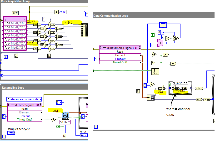
If you use other types of modules in the example, you must take care of the conversion of accuracy in the FPGA VI.
As FPGA VI resampling takes the signal of type fixed point +-24.1, you convert the +-24,10 and-24,5 to 24.1 in the Data Acquisition loop before feeding to the FPGA VI resampling.
And in the loop of data Communication, you restore the output of +-32,3 to 32,12 - signal + and +-32.7. Notice at the time the zoom in and zoom out are equal.
If you change other types of modules of different precision, you must change the precision of the given thread.
For example, 9244 accuracy is +-24.11, so when you convert it to +-24.1, you must restore it by variation of-32,3 to-32,13.
Please refer to the screenshot:
-
Configuration of the basic Source of time to master for the 9234
I have several cDAQ modules I use to collect data. I use vi to Write can Express to save data to a file of PDM.
When you examine the recorded data files, the measured data from NI 9215 provide pleasant timestamps to match how the DAQmx task has been set up--delaying the sampling frequency of 1000 with a 1 ms in the While loop. However, although in the same vi - different tasks, but the same while loop - horodateurs of the NI 9234 do not correspond to the task of DAQmx implemented - sampling frequency of 1000 with a 1ms delay. After reading the material provided with the NI 9234, I found that maybe the machine clean master Timebase Source. There were documents that says he can be configured to be originally of Timebase of Master for the other modules:
Configuration of the basic Source of time of the master for the NI 9234 (Interface FPGA)
It is desirable to have the timestamps for data measured across all modules to match. We do not have the FPGA Module for LabVIEW. Is there a method in LabVIEW for all modules use the same master time base Source? I assumed that because all the data collection has place in the same while loop by using the time delay of 1 ms it was forced through the code. This hypothesis seems incorrect from my review of the PDM data files.
The NI 9204 provides a trigger only.
Software:
Windows 7
LabVIEW 2010 SP1
Material:
CDAQ-9174 chassis
Slot 1: NEITHER 9204
Slot 2: NEITHER 9215
Slot 3: NEITHER 9234
Slot 4; Vacuum
Hi MgDAQ,
An important concept to note is that the 9234 uses a delta-sigma converter and a clock of oversampling to read analog data. There is an inherent delay of entry due to analog and digital filtering built-in. Since the 9215 has a lower resolution there will be a lag the 9234 and 9215 finished. I've included some resources below:
What are the for the NI 9233, NI 9234, and NI 9237 valid sampling rates? : http://digital.ni.com/public.nsf/allkb/593CC07F76B1405A862570DE005F6836?OpenDocument
Synchronization of DSA, S and X series devices with a NEITHER-DAQmx single task series: http://digital.ni.com/public.nsf/websearch/78E44565FD87E7D686257108007F94F8?OpenDocument
Synchronization with NOR-DAQmx of acquiring dynamic signals (DSA) products:http://digital.ni.com/public.nsf/allkb/A133ED27DF9BCC5986256F2E004BA342?OpenDocument
Have you tried to put two modules in the same spot? Alternatively, you can export the sample clock 9234 and tasks installation separately.
Best,
CARISA
-
cDAQ HAVE task using external clock
Hi, I am trying to use a clock signal on a line of PFI in order to generate a clock, but at a lower rate, for a task to HAVE. I run into many issues that I can't explain.
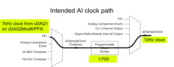
I have a cDAQ-9172 with an entrance module analog (9225) in the Groove 3 and a digital input module (9411 - 2 MHz DI) into the slot 6 (where the PFI lines are accessible). I want to use an external signal on et0/PFI0 to act as the clock for an analog input on the 9225 task. This signal comes from the cDAQ anothr chassis and is too fast for the task to HAVE it, so I intend to use the time base entrance and the divider to clock (as shown on page 31 of the cDAQ-9172 manual). See picture attached for a graphical representation of my problem.
If I have the wiring from the signal "/ cDAQ2Mod6/PFI0" in the DAQmx timing VI, get the error 200414 saying that "required sample clock source is not valid." It is strange because it is listed as "Direct route" in Max (the VI of polymorphic DAQmx Timing is configured as 'Sample clock') Q: why this route is not suitable for the task?
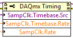
If I use DAQmx Timing property node and change the Source 'Sample clock Timebase' to ' / cDAQ2Mod6/PFI0 ", the task starts without error, but the separation seems to be forced to 256. If I try to change the properties of the separation of the time base, I get error-201100. Try to change the 'sample clock rate"doesn't have any impact on the task and the remains of divider"256 ". Q: why the 'Programmable clock divider"locked to 256 when using the PFI line or can you just not program directly?
I came across another error is the minimum speed on the PFI line. If I have the wiring (for the SamplClock Timebase) lower at 1 MHz, LabVIEW returns error-200077. The error message indicates that the minimum value is 1 MHz. 9172 manual shows the clock 100 kHz is an option for the time base, certainly less than 1 MHz. Q: What are the limits of upper and lower frequency for a clock signal on the line PFI for the ' Timebase AI/SampleClock "?
I looked on the site and in the DAQmx documentation for further explanation, but I have been unable to explain these strange behaviors. What are the barriers to entry of Timebase PFI and the time base "Programmable clock divider" preventing me to reach my goal here? If I can't do it directly, can I use the PFIn signal to feed an internal counter (to act as the clock divider) which could then generate the clock WAS at the rate I want? This method would allow me to perform a division arbitrary clock (unlike the ' 256', which seems to be forced on the PFI as a Timebase SampleClock.)
Finally, something seems odd that I can make an acquisition to 10Sa/s max but when I start a task using an internal timers of the cDAQ9172 and ask a 10Sa/s rate, the task really gives me a rate of 1612.9 sample/s while using the 12.8 MHz clock and a divider 7936 timebase. Q: Why can't the task to 10Sa/s?
I use DAQmx 9.7.0 and LV2012 SP1 (and I tried with 9.7.5 but I got the same results)
Thank you
Olivier
I got additional help Friday in another engineer at NEITHER and the solution to my original problem is actually very simple to get the clock from an external source path:
The idea of picking a PFI line for the basis of 'time' and the 'Programmable clock divider"(in fact, DAQmx calculate this number based on"HAVE sample time clock"and"Sample clock HAVE") works by using the node property below:
(SampleClock.Source cannot be resolved until the task is clerks/reserved, but the default option seems to be the time base that works well in this case.)
The question that I described earlier with the 9225 comes the module properties and the fact that it is a "Module of Sigma - Delta". That the module usually generates its own time of 12.8 MHz base clock (page 14 of the document 9225 # 374707) and the clock divisor is much less possible values than the other modules (must be a multiple of 256). It may use a different time basis from a PFI line, but it must be between 1 MHz and 13.15 MHz.
So a main clock between two chassis and tasks running at different rates of sharing should be easy and simple with most of the modules. With AI modules with Sigma-Delta converters add additional limitations and the master clock for the time base frequency must be selected to accommodate these module as well.
Another good news is that the Simulator seems to bear all these details and DAQmx (9.7.0 in my case) generates the same errors when you use a simulated chassis if you use real body. Play well!
-
NEITHER USB 4432 readable voltage i.e. the ASPM signal conditioning
Hello
For what I understood that the USB-4432 entries must read IEPE accelerometers report. Read a voltage signal conditioner of my sensor ASPM IE using the option 'IEPE-off with AC coupling.
Thank you
1. What if I use the 5th cahannel of
4432 read the square wave pulse width, i.e. the digital signal
tachometer using any function of sounds or labview software and
Vibration Measurement Suite. If so, how precis specific will be read
frequency (speed) compared to meter modules.Channel 5 is the same as the other channels of the 4432 except it lacks excitement IEPE and TEDS. I can't really say how "accurate", it will be at a faster rate because of the delta-sigma ADC. Someone else wants to chime in on this one?
2.
Is available to trigger analog acquisition of digital triggering. If so, is
It possibel to read all 5 channels togather in a single task.You're talking about!
3.
If there is only one PFI then is possible to trigger two
different tasks, i.e. a task of 02 strings with front amount and
a further task of 02 channels with the falling edge of the PFI even.There are 8 PFI lines, but can only be used on the device at the same time (it might as well be one PFI). You must have all the channels you want to raise in a task and use one as the trigger for starting digital PFI lines. (i.e. 'no'
 ... have a stain on the front and the other on the falling edge won't work, a task only by digital triggering)
Germano-
-
synchronize two cDAQ Chassis with DAQmx 9188
I try to sync analog entry tasks on two 9188 Chassis utilzing the build in the BNC (PFI 0 and 1) ports. I also have digital entry spots on the chassis of the master, I want to synchronize. Have been referencing http://www.ni.com/tutorial/5376/en/ and examples, I am not sure I have it set up correctly.
From the link above, I exported the SampleCLK to PFI0 and StartTrig to PFI1 on the chassis of the master. I have two BNC cables routed between ports on the two chassis. I put the trigger DAQmx start on the slave to the PFI1 source (this does not seem to do both tasks at the same time), I tried to adjust the pitch of the DAQmx (sample clock) of source PFI0, but it creates an error (requested sample clock source is not valid).
I can get the application of test runs by seting the slave clock "OnboardClock" sample source When I use this setting, the task two seem to start at the same time, but I don't think the slave chassis uses the master module sample clock and therefore might drift over time?
I would like to know how to properly synchronize the two analog tasks. I also want to synchronize digital tasks on the main frame with the analog task.
Hello
If you want to synchronize the two tasks, you share examples of clock and triggers via PFI lines. The only exception is that it is not currently possible to synchronize tasks between the chassis that use AI modules with delta-sigma a/d converters.
Best regards
Villanueva of the DSL.
-
I tested the FIFO DMA method without success. I copied the example of OR and you can see the target and the attached Hostcode. I read a 4 channels/a. 9234. What I get is nothing and I get a FIFO overflow every time. (which prevents the host program).
I do something wrong, it's obvious? I can post the screws so communal. I use a CRIO-9022 and 9114 chassis.
concerning
Tom
The 9234 is a DSA (Delta Sigma ADC) device and is clocked away from the clock of the FPGA, but by its own internal clock. 9234 a built in anti-aliasing filters, which trace the sample used by its own clock rate internal.
If you do not set a specific sampling rate, then the jury 9234 will run at the fastest pace - 51.2 KHz. Its Anti-Aliasing filter is moving at about 22 kHz. If you don't start on the FPGA, no data is produced.
Discover the reference waveform link (first one above), and see the best practices for the use of DSA in FPGA modules.
If you look at your node IO error code, you will see that this module has not been started (in your code).
-
Determine eligible SampTimingTypes for a given device?
I'm sure that this should be simple, but I can't find the right way to determine if a device supports the synchronization of DAQmx_Val_OnDemand. For example, I can get a list of the modes supported by using DAQmxGetDevAISampModes sample; Is there an equivalent for the types of synchronization?
Ultimately I do simple analog sampling and want to use synchronization to the application as soon as it is available, clock sampling timing also. Thank you in advance for any advice!
QueenSelene,
It is in fact not true. DAQ hardware will support usually static/on request/timing software acquisition on analog I/o if they were converters a/d SAR. Devices that contain dela-sigma a/d converters fall into two categories: slow sampled (typically for measures DC strain, temperature, voltage, current, etc.) and fast sampled (typically for dynamic measures of vibration, bridge, audio sensors, etc.).
Delta-sigma sampled slow devices can often be software timed (on request). Sigma-delta fast sampling devices are usually not able to support this mode.
micahsimonsen,
I see no immediate way to interrogate the task for this mode of synchronization, because, from the point of view driver DAQmx, calendar on demand is not a synchronization mode, but rather a lack of a mode of synchronization. If you were to query the property you mentioned in your message and got no valid results, you might assume that calendar On Demand is supported because the unit will need support at least one mode of operation (otherwise you could not use it). However, if you have received results valid (sample clock, HWTSP, etc.), it would be for a period indeterminate as to whether or not your device support on request because there is at least one other valid mode of operation.
Is there a particular set of devices you want to cover in this application? You might still question the task of the device name, and knowing what you know about the individual devices or device families, determine whether on-demand synchronization is supported. For example, devices 60xx 61xx, 62xx and 63xx (to the best of my knowledge) should always support synchronization On Demand, while most of the 44xx and 43xx devices will not. C series becomes much more complicated in terms of numbering systems, but you could apply a similar methodology to maintain a list of devices that support and compares with this list. According to the extent of the coverage of device you want your application to have, and the complexity of your comparison algorithm could be reduced to a minimum.
Another potentially more robust to treat this way may be to run a fictional task which bed/written one sample on request to see if the task with a particular code errors indicating that the time to demand is not taken in charge. You can handle this error and continue accordingly.
Kind regards
-
I develop a proof of concept in BT 8.5.1 application uses the comforter of cRIO-9012 real-time with FPGAS 1 million 4 connector chassis and I have problems affecting the duration of the scan on the FPGA. I have attached a picture of my FPGA diagram and my application RT block diagram so I don't have to go through a verbal description of my code. My problem is that my scan FPGA rate won't go faster than 3 Hz. I put the timer loop ms County on the FPGA of the application of the RT, and then I say the FPGA to start execution of the DAQ by "arm data acquisition. During the loop DAQ, if I put the Count (mSec) less than 333 mS my time-out indicator again relates that loop rate is not keeping up with the time limit. In my app RT I am followed if there is an overflow of DMA and how many items is still in the memory buffer DMA, both indicate that the FPGA loop and the loop of RT are run synchronously when I had if I had programmed the FPGA loop to run as fast it must maintain the "sampling rate". I know because the application of the RT signals there are 0 items remaining in the buffer for DMA.
I have a feeling that the problem can be explained by the fact that I do work the application of RT through a remote façade. I do this because this application is a proof of concept, and I wanted to avoid having to spend too much time in writing an application of FPGA, a RT application and a host application. The fact that the front of the RT has to update remote some how causes the FPGA vi run differently.
I tried to follow the abundant examples of NEITHER, but I can't seem to find a reason any for the performance of the slow loop on the FPGA.
Hello
I think you have a problem with the type of module you are using. Mod4 seems to be a module 9211, given that you have channels like TC with a CCM and a track. The 9211 is a 24-bit delta-sigma module and has a slow conversion time.
Conversion time... 70 ms per channel; total for all channels including channels of the track and the cold junction 420 ms
FPGA loops can ONLY run as fast as any I/O in their breast works. In your case, the 9211 module has an of70ms of conversion through time and manual States that the module will take ms 420 for all channels (4 stop TC, CJC &). I am somewhat surpised that you can get the loop to run at 333ms. If you do not need to have a faster rate loop, then you have to divide your I/O in different loops.
If you need a faster themocouple reading then you must consider using another module to measure the mV and do the conversions yourself, or consider using probes to resistance and a 9217 that has a high resolution and a mode high speed.
Conversion time
Mode high resolution... 200 ms per channel; 800 ms total for all channels:
Mode high speed... 2.5 ms per channel; total for all channels of 10 ms
See you soon
Stephen
-
Scan USB 4431 DC analog output voltage
Hi all
I have NI USB 4431 Analyzer of dynamic signals. I want to generate constant tension on the port AO0 of this material. I tried to use the Gen Update.vi blood sample, but it is said that only updated the HW Timed mode cannot be used with this equipment. When I use the Test of MAX Panel, I can generate a constant tension.
How can I make it happen in Labview? Can someone help me?
The USB-4431 can be used to generate a voltage, but to do this, you actually create a timed task equipment. This is because it uses a DAC delta-sigma, which must be clocked to produce output. To do this, I would recommend that you set up the device to perform a finite generation. The data you write are just the DC value that you want to copy, repeated. Then you want to define the area of OCCUPANCY. Property of IdleOutputBehavior. In LabVIEW, this is located in DAQmxChannel-> outputs Analog-> General Properties-> output Configuration. In the C API, you would call DAQmxSetAOIdleOutputBehavior to DAQmx_Val_MaintainExistingValue.
To summarize:
(1) create output over task
(2) configure the IdleOutputBehavior property
(3) write the data (value of DC, repeated)
(4) to start the task.
This should lead to the value of the DC output.
Hope that helps,
Dan
-
Acquisition of vibration with the NI USB-9234 using the NIDaqMxBase library
I have a NI USB-9162 linked to a NOR-9234 properly configured and installed under OpenSUSE 11.3. It's the output of ldaq:
>lsdaq
--------------------------------
Detecting National Instruments DAQ Devices
Found the following DAQ Devices:
NI USB-9234: "Dev1"    (USB0::0x3923::0x72B5::0164852A::RAW)
--------------------------------
I'm developing a simple application to acquire the values of vibration of a project connected with an accelerometer.
We start from the example of acquireNScans - AnlgStart.c of NIDaqMxBase 3.4.5 documentation.Unfortunately, the program fails and generates the following error:
"DAQmxBase Error -200428: Value passed to the Task/Channels In control is invalid."
Then I realize that the NI9234 doesn't support analog and digital triggers so I have decided to try with the acquire1Scan.c (a scan without triggering):
int main(int argc, char *argv[])
{
    // Task parameters
    int32       error = 0;
    TaskHandle  taskHandle = 0;
    char        errBuff[2048]={'\0'};

    // Channel parameters
    char        chan[] = "Dev1/ai0";
    float64     min = -10.0;
    float64     max = 10.0;

    // Timing parameters
    uInt64      samplesPerChan = 1;

    // Data read parameters
    float64     data;
    int32       pointsToRead = 1;
    int32       pointsRead;
    float64     timeout = 10.0;

    DAQmxErrChk (DAQmxBaseCreateTask("",&taskHandle));
    DAQmxErrChk (DAQmxBaseCreateAIVoltageChan(taskHandle,chan,"",DAQmx_Val_Cfg_Default,min,max,DAQmx_Val_Volts,NULL));
    DAQmxErrChk (DAQmxBaseStartTask(taskHandle));
    DAQmxErrChk (DAQmxBaseReadAnalogF64(taskHandle,pointsToRead,timeout,DAQmx_Val_GroupByChannel,&data,samplesPerChan,&pointsRead,NULL));

printf ("Acquired reading: %f\n", data);
Also this program fails and gives this error:
DAQmxBase Error -200077:
Requested value is not a supported value for this property. (Timing Mode) How can I get at least a single data value of the accelerometer of the device using the NIDaqMxBase API?
Hi giaulo,
The examples that you have tried to run are not compatible with your device.
The 9234 does not support analog triggering, so examples of "acquireNScans" - AnlgStart.c do not work.
He is also unable to make an acquisition of single point because is based on the architecture of delta-sigma ADC. Here is a knowledge base article explaining the limitation:
KB 4SU94SH7: DSA Hardware Support a Point Acquisition?
This is the reason why the "acquire1Scan.c" does not work.
You will need run one example making an acquisition in the buffer. "acquireNScans.c" would be a good to watch. Be aware of all these examples, the default is +/-10V input range. The 9234 can only input +/-5V, so it will take a few changes. Also as you try to read an accelerometer, IEPE excitement is probably necessary. I've attached an example which is based on the example of "contAcquireNChan.c" that defines the range and allows the excitement for the device correctly.
-
PXI-4461 generate voltage update
Hello
When you try to run the sample Daqmx VI "Gen - Update.vi of tension" with an NI PXI-4461, I get the following error:
200758 error:
"Type of sample Timing is set to on demand that is not supported for analog output on this unit"
What does that mean?
Is there another way to generate a constant DC signal with the 4461?
Also - for next time that consider us to buy a new card - where can I get information on DAQmx properties (like this one) are supported for each camera?
Thank you
Ran
Hi Ran,
The 4461 NOR supports HAVE no single-point / AO of because it is based on delta-sigma converters a/n/CED, which require a clock free run at a constant speed.
There are two ways to output a signal DC with an NI 4461 (or NI 4431):
- Continuously to generate a waveform to DC (containing several repeated values).
- Set channels DAQmx > AO. IdleOutputBehavior to "Maintain the existing value" can generate several updates.
The help of LabVIEW has a page of "properties of the NI PXI-4461 supported", but it does list all the supported values for each property for each device. NOR-DAQmx help has a page entitled "Considerations for DSA timing devices" that talks on this subject:
"
Considerations of timetable for DSA devices
Supported sampling frequencies
Unlike some other devices DAQmx, DSA devices have a maximum and a minimum sampling frequency. Check your device specifications determine the range of sampling frequency.
Other considerations of DSA calendar
DSA devices do not support the type of synchronization on demand. All acquisitions of DSA and generations require hardware timing of a stable clock.
DSA devices do not support external synchronization sources of arbitrary external signals such as tachometers and encoders. PFI lines on the DSA hardware can accept external clocks. You can program a DSA device to use an external clock only when it is a slave in several synchronized system device. Refer to synchronization of the DSA for more details.
"
Brad
-
Hi Jeff,
The first thing that you should start with is a guide to the delta sigma converter:
It is the ADC that is used on the 9233. The delta sigma converter has a built-in inherent anti-aliasing filter. If you look at the dynamic features section of 9233 operating manual it will show you some of the features of this filter. The filter is a digital and the bandwidth and the stopband are calculated according to the sampling rate, you specify the 9233. If you give a sampling frequency of 50 kHz,-3 dB attenuation point bandwidth will be 50 k * 0.45 = 22.5 kHz. If all the components below 22.5 kHz will be kept completely and everything above that will be alleviated. This ensures that you will get no aliasing.
If you apply a 20 kHz filter after that you'll still good data because the threshold for the anti-aliasing filter is greater than the maximum sampling frequency (50 kHz).
Please let me know if this clarifies this question a little better.
-
Lack of first samples using digitizer Tclk and function generator
Hello
I have a pxi-5922, an arbitrary signal 5412 generator. They are synchronized due the Tclk. The question I have is that I can not capture the start of production of function generators. I tried the positions of different reference for the scope, but am unable to quarter at the beginning.
I tried to have the function generator and digitizer as the master, this does not seem to help with my question.
Is there something else I could try to capture the start of the release of gen func using Tclk.
See you soon,.
Brett
So the 5922 has a delta sigma converter that will cause a delay of the sample during synchronization with other cards, the same as our DSA cards. It is the delay of the sample we see and has nothing of synchronizy we can do to get rid of him. What I would recommend is to generate samples 62 "junk" at the beginning of your waveform.
Maybe you are looking for
-
Re: Blank screen on laptop Satellite Pro
Advice please - my son released a disc of a game that he played and the screen went white. She always had the slider, however. I rebooted it and although the screen shows the normal screen displays, it is emptied once it's over. Any ideas would be ap
-
the procurement process from the shock of the clans the amount was deducted in full and did not get the gems has helped me
-
HP dv6 envy: want to know on the best internal hard drive to replace it with
Hi friends... I return my hp dv6 want 3 years and it has worked well for me so far, but since last month, everytime I turn on my laptop, a message is popping indicating that YOUR HARD DISK has FOUND YEAR IMMINENT FAILURE AND there NEED TO BE REPLACED
-
Hello world I have a txt file and it has some data. Specifically, I want to replace a character in the text file. Data will be like this. TT = 15S1ST = 21601S1EN = 50400S2ST = 50401S2EN = 72000S3ST = 72001S3EN = 21600GNST = 00000GNEN = 00000S1B1S = 2
-
Error: C00D11EF while using Windows Media Player to synchronize the iPod
Original title: Installed a new drive, iPod syncs not; using MGTEK for conversion. Remember - this is a public forum so never post private information such as numbers of mail or telephone! Ideas: You have problems with programs Error messages Recent