Scan USB 4431 DC analog output voltage
Hi all
I have NI USB 4431 Analyzer of dynamic signals. I want to generate constant tension on the port AO0 of this material. I tried to use the Gen Update.vi blood sample, but it is said that only updated the HW Timed mode cannot be used with this equipment. When I use the Test of MAX Panel, I can generate a constant tension.
How can I make it happen in Labview? Can someone help me?
The USB-4431 can be used to generate a voltage, but to do this, you actually create a timed task equipment. This is because it uses a DAC delta-sigma, which must be clocked to produce output. To do this, I would recommend that you set up the device to perform a finite generation. The data you write are just the DC value that you want to copy, repeated. Then you want to define the area of OCCUPANCY. Property of IdleOutputBehavior. In LabVIEW, this is located in DAQmxChannel-> outputs Analog-> General Properties-> output Configuration. In the C API, you would call DAQmxSetAOIdleOutputBehavior to DAQmx_Val_MaintainExistingValue.
To summarize:
(1) create output over task
(2) configure the IdleOutputBehavior property
(3) write the data (value of DC, repeated)
(4) to start the task.
This should lead to the value of the DC output.
Hope that helps,
Dan
Tags: NI Hardware
Similar Questions
-
Hello
I have a power meter which provide the USB driver and a Labview program to get the data and NI USB-6221. The project I am currently working on the needs of:
1 acquire two signals (inputs of simple tension), pressure frequency KHz
2. acquire a flow signal, the output signal is 0 to 5V pulse, each pulse means 0.4 ml volume. So I use a voltage inflows to count impulses in certain period of time (in this case, 1 S) for water flow. ; KHz sampling frequency and the 1 Hz update rate
3. acquire a signal of engine speed. The output signal is pulse square wave whose frequency is related to the speed. I use a REIT port to measure the frequency. Sampling rate: Auto
4 give output voltage sine or square wave, I use AO do that.output rate: Auto
5 acquiring by VISA electricity meter data. Data update rate: every 50ms
Currently, all the 5 tasks work well separately. But when I put them together, some signals are beginning to hang, for example, pressure signals sometimes give nothing.
Another problem is the data record. I programmed the VI in such a way that whenever I press the button 'save start', he begins to record data and save them in a .cvs file. For some reason, I always get only the data in the first table. Coult someone help me? I download my code as follows
Hello
What I meant by open, write, close. For any type of file you are using.
Open the file, which produces a reference, then put the mention in a registry to offset.
Write data, using the function write (for this type of file) and the reference.
When you are finished, close the file reference.
Writing in the spreadsheet opens, written, close all at once. It is very good for this type of application.
***
The issue of the loop is more general. I would like to say first of all, I want to say that since each loop works on its own, it is own VI, and that this program has put all this into a single VI, which has a method to solve the problem is to disable all the loops and allow them one at a time to see if there is a culprit responsible for.
Using multiple loops executes the code at the same time, and some loops would be cycle faster than others, especially if some of them are loops just as they are.
Communication between the loops is a test to the address if necessary.
Running all these signals through different loops DAQ must also be examined. Don't know what questions are for read and write somewhat randomly in the channels.
-
Question about multi analog outputs voltage outfit
I am programming my NI USB-6008 with V ++.
Now, I have a question. The unit has 2 analog outputs.
When I put the "ao0" channel to a certain tension, then stop this task. Start another task, then the string value "ao1" some tension. When I do the second task, ao0 held the voltage set in the first task?
Thank you.
Hi Lowsfer-
Yes, the analog output of AO1 status will remain in the last State it was before the task is stopped. As long as the device is not reset or the computer is not turned off, the analogue output will maintain the last tension that you specified, regardless of what did the other Ao channel.
I hope this helps. Good luck with your application!
-
Error-200524 when you try two analog output voltage signals
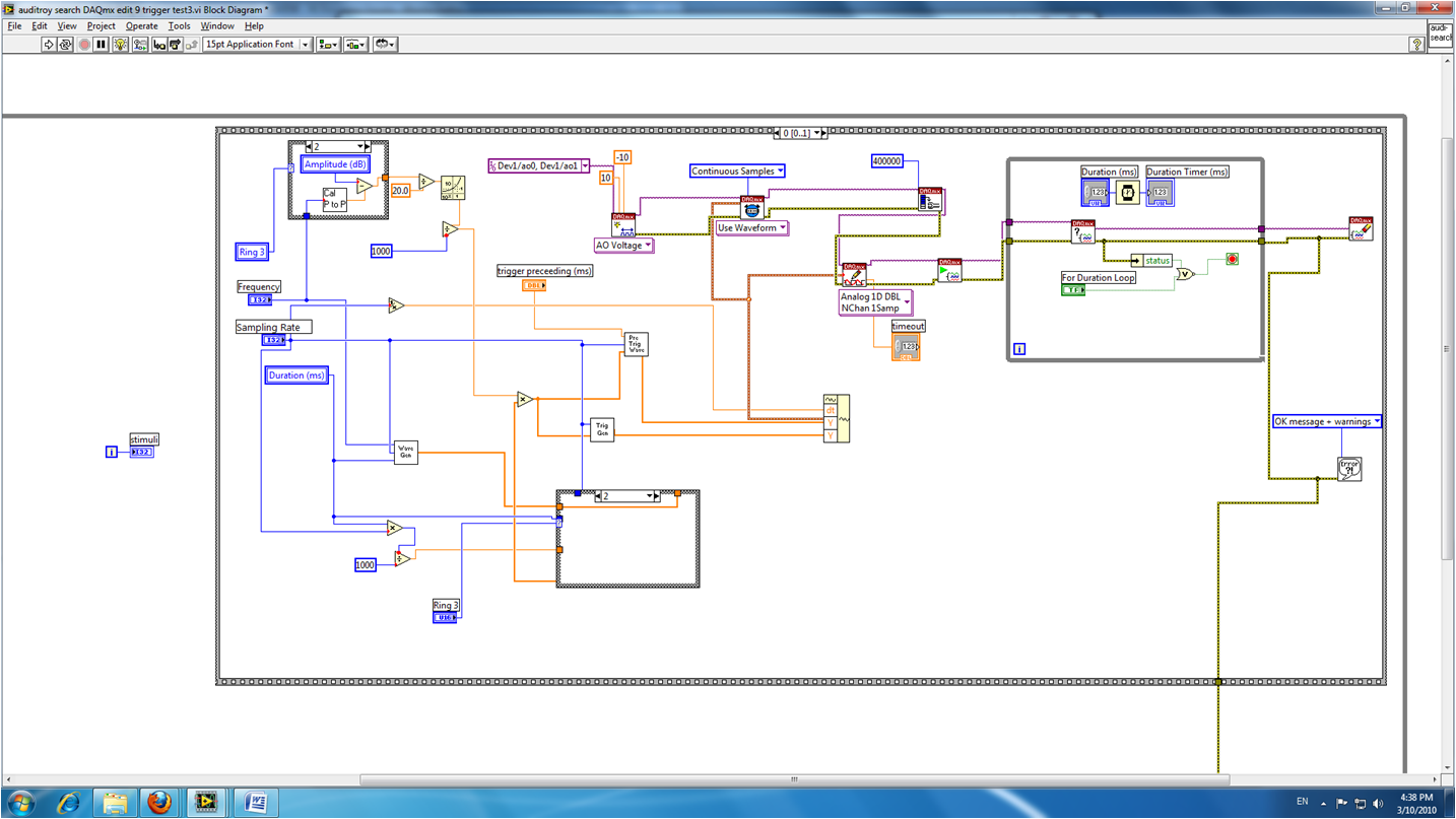
I am train to the output of two signals to analog voltage simultaneously using Labview 8.2.1. One is a waveform to produce sound, and the other is a trigger on another computer (using labview 6.1). I've been doing error-200524 write DAQmx. Here is a screenshot of my VI:
The error message says:
"Measurements: writing cannot be performed because the number of data channels does not match number of channels in the task."
When writing, provide data for all channels in the task. You can also change the task so that it contains the same number of channels as the written data. "How can I solve this problem? Thank you.
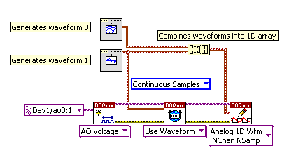
Show you only a waveform in the block diagram.
Here is a picture that shows what I told you to in my previous post.
The waveform connected at element 0 of the 'picture to build' will be emitted on channel 0. The waveform that is connected to the item 1 of the 'picture to build' will be emitted on channel 1. The instance of 'DAQmx writing' is 'Analog 1 D Wfm NChan NSamp.
Hope that is more clear!
d
-
Strange analog output of USB-6211
I just got USB-6211 to replace USB-6001 to set the clock to external sampling on analog output for LED lighting control. The part of external clock example works fine, but the analog output voltage is strange. To do self-monitoring, I connected control pin LED to AO0 & AI0 of surveillance in the NI MAX test panel and LED control on the ground at AO - GND & GND HAVE since I have both USB-6001 and USB-6211, I conducted tests on two of them with the same setting of wire. When I generate sine wave - 5V to 5V to AO0 (from NI MAX test panel), USB-6001 can monitor the same signal AI0, but watch USB-6211 - 3, 4V to 3.4V voltage truncated. I did the test separately (wiring one device at a time), so there is no interference between the two devices. USB-6211 past self-calibration and self-monitoring. Also, I did reset devices. I don't know why they would behave differently with the same configuration, and I hope that someone could help with this question. Thank you.
Hi skuo1008,
The USB-6001 can support + / 5 output current my from terminals to analog output, while the USB-6211 box can provide only +/-2 my current output. It is likely that the load impedance is too low, causing the 6211 to hit its current compliance and thus cut the tension. If you try to exchange your load with a resistance of at least 5 v/.002A = 2500 Ohms, you should be able to see the full +/-5V sine wave. I suspect that your DUT has a words 3.4V/.002A = 1700 Ohms impedance. You could use a device with higher output current or use a more current source buffer circuit. If you do not need a bipolar output, you might also consider using digital lines to control the LEDs.
Kind regards
-
acquire the voltage output of a channel of analog output current
I'm controlling a HV configuration rather sensitive analog output voltages. Is there an easy way to read the voltage level which is currently awarded by an analog output?
Hello
If you set your subVIs different voltages, you can be sure that the voltage you set in these screws are similar to tensions, you have to your output PIN. For example, you could write the value you give to the output in a variable and read this variable in you main VI.
Kind regards
Peter
-
Bad analog output help Every_N_Samples-NI-9263 cDAQ-9172 chassis (works with cDAQ-9178 chassis)
Hello
The NOR-9263 analog output voltage geberation works correctly with the cDAQ-9178 chassis but gives wrong result using the chassis NOR cDAQ-9172.
In the attached code example, a single cycle of a sine wave is composed of 40000 samples and came out in the background using Every_N_Samples at a rate of production of 5000 samples per second.
The output buffer size is set to 10000 samples.
Prepare us the buffer writing 10000 samples 1, then write the remaining data in the background using the Every_N_Samples callback.
Bug: Using the cDAQ-9172 chassis, to the 5000 s/s sampling rate with the help of an external field (or through closure to another HAVE), we observed that 1 10000 samples came out twice, followed by the rest of the waveform. The last 10000 samples are never exits. If you are working properly, we would expect to see 1 full cycle of a sine wave.The bug does not occur with the chassis NOR cDAQ-9178. I use the driver NIDAQmx v9.2.1f0 on Windows XP
The bug does not happen with simulation devices, so you will need to use harwdare real to reproduce.Please find attached an example of code C based on the example program OR "ContGen - IntClk.c" to reproduce this bug.
Thank you
whemdan,
The MathWorks
Hi whemdan,
By default, DAQmx regenerate old samples if no new data is available. To give the correct behavior, you can:
Use DAQmxSetWriteRegenMode to disable the regeneration (DAQmx_Val_DoNotAllowRegen). In most cases, this is recommended if new data are written continuously in the buffer as the build is in progress.
If you just need to generate 40 k samples, you can write them just all at once, rather than in 10 pieces of k (the code you attached probably is just an example, so I'll assume that you have a reason to write the data into segments in your actual code).
I think the difference in behavior between 9172 and 9178 can if explained by the different way, buffering is set up on each product. The 9172 uses a buffer of 8 k (on the STC2) in all cases (source). The 9178 uses an 8 k of memory buffer (on the STC3) If you use regeneration shipped, but uses the 127 samples FIFO cartridge, if you use no on-board regeneration (source).
Then... on the 9172 8191 samples are immediately transferred to the FIFO. By default, the hardware is going to request new data when the FIFO is less to fill (this is configurable with DAQmxSetAODataXferReqCond). I'm not sure what the transfer data request size is in your case (you can set the maximum value with DAQmxSetAOUsbXferReqSize), but obviously it is bigger than the other 1809 samples that you have not yet sent to the Board of Directors of your first entry. At this point, the pilot will regenerate 10 existing k samples so that sufficient data will be available to meet the demand of data transfer.
The 9178 however use the FIFO of 127 smaller samples so you will not have the same behavior in your case.
In summary, the behavior is explainable by the difference of material. If you want to avoid to regenerate old samples, you should ban the regeneration using DAQmxSetWriteRegenMode.
Best regards
-
Problem of generation of the analog output on PCI-7342
I use for the control of servo motor with encoder Axis 1 of my PCI-7342 feedback
and trying to out of the velocity of the encoder on the analog output of the axis-2 which is currently not used.
For testing purposes, I pulled out a constant 16383 (half of 32767) to the analog output
through load DAC.flx permanently, but there is no voltage on the map of the motion.
I read
http://digital.NI.com/public.nsf/WebSearch/102BE3EEED8A8B0DC1256EDA0059EC47?OpenDocument
and configure my 2 axis to be a stepper motor. I also tried to disable axis - 2. None of them works for me.
Also, I tried to read the value of CAD using reading DAC.flx right after that load DAC.flx is called.
Correctly, the value was shown on the screen. (See the attached figure)
I'm really bad now. Please, please, please help!
Any possible solution is fully appreciated!
Ron Liou
-
Analog output on USB6008 in C ANSI does not work
I tried to program the analog output on a device of USB6008 under MSVC ++ 6.0 with the latest NOR-DAQ 8.8.
The lines of the example of the ANSI C program ' MultVoltUpdates - IntClk.c ' work very well with a device emulator, but not as soon as I try to access the real device of USB6008.
/*********************************************/
DAQmx Configure Code
/*********************************************/
DAQmxErrChk (DAQmxCreateTask("",&taskHandle));
DAQmxErrChk (DAQmxCreateAOVoltageChan(taskHandle,"Dev2/ao0","",-10.0,10.0,DAQmx_Val_Volts,NULL));
DAQmxErrChk (DAQmxCfgSampClkTiming(taskHandle,"",1000.0,DAQmx_Val_Rising,DAQmx_Val_FiniteSamps,4000));During the call to the last line concerning the synchronization setup, an error occurs:
________________________________________________________
DAQmx error: measurements: request the value is not supported for this pro value
Property.
Property: DAQmx_SampTimingType
You asked: DAQmx_Val_SampClk
You can select: DAQmx_Val_OnDemandTask name: _unnamedTask<0>
State code:-200077
________________________________________________________
Is there a work around?
Finally, I want to set unique values for the analog output voltage in a loop.
In commenting on the "DAQmxCfgSampClkTiming" call, no voltage is defined in a "DAQmxWriteAnalogF64" call to handle this task.
Thanks for the tips!
'DAQmx_Val_OnDemand' is not a valid option for "DAQmxCfgSampClkTiming...." and leads to errors of execution, if I put it anyway.
As an alternative, I tried in the meantime:
DAQmxErrChk (DAQmxCreateTask("",&AO_V_taskHandle));
DAQmxErrChk (DAQmxCreateAOVoltageChan (AO_V_taskHandle, dev + ao0 "",""-"))
0.0,5.0,DAQmx_Val_Volts,null));DAQmxErrChk (DAQmxSetSampTimingType (AO_V_taskHandle, DAQmx_Val_OnDemand));
DAQmxErrChk (DAQmxStartTask (AO_V_taskHandle));
DAQmxErrChk (DAQmxWriteAnalogF64 (AO_V_taskHandle, 1, 0, 1.0,-))
DAQmx_Val_GroupByChannel & data_v_out, & writing, NULL));
(data_v_out = 2. ;--> back: written = 1) not--> no measurable output voltageDAQmxErrChk (DAQmxStopTask (AO_V_taskHandle));
--> still no measurable output voltage
Any other idea?
-
Want a ramp of output voltage over time and measure input 2 analog USB-6008
Hello
I want to produce an analog voltage output signal that increases over time with a certain slope, which I'll send in a potentiostat and at the same time I want to read voltage and current (both are represented by a voltage signal) that I want to open a session and ultimately draw from each other. To do this, I have a DAQ USB-6008 system at my disposal.
Creation of the analogue output with a linear ramp signal I was possible using a while loop and a delay time (see attachment). Important here is that I can put the slope of the linear ramp (for example, 10mV/s) and size level to make a smooth inclement. However when I want to measure an analog input signal he's going poorly.
To reduce noise from the influences I want for example to measure 10 values for example within 0.1 second and he averaged (this gives reading should be equal or faster then the wrong caused by the slope and the linear ramp step size.) Example: a slope of 10 mV/s is set with a 10 step size. Each 0.1 s analog output signal amounts to 1 mV. Then I want to read the analog input in this 0.1 s 10 values)
Because I use a timer to create the linear ramp and the analog input is in the same loop, the delay time also affects the analog input and I get an error every time. Separately, in different VI-programs (analog input and output) they work fine but not combined. I searched this forum to find a way to create the ramp in a different way, but because I'm not an experienced labview user I can't find another way.
To book it now a bit more complicated I said I want to measure 2 input analog (one for the voltage of the potentiostat) signals and one for the current (also represented by a voltage signal) and they should be measured more quickly then the bad of the analog signal. I have not yet started with because I couldn't read on channel work.
I hope someone can help me with this problem
An array of index. You want to index the columns for a single channel.
-
It is current on the analog module USB NI 9263 output voltage limit (+/-10 v)?
It is current on the analog module USB NI 9263 output voltage limit (+/-10 v)? I try to run a current controlled resistance, but cannot get the required current. The servovalved has a parallel internal resistance of 80 ohms and requires 20 my full operation. Ohm's law: (.02 A) * ((80*80) /(80+80) ohms = 4.5 v) Yet, the required voltage, do not move the servo. Outside the material error (continue this by other means), what could be the problem?
Have you checked the Manual?
Page 12 1 says my.
For servo, you really need some kind of amplifier. See if the manufacturer provides the electronic driver for it.
-
Simple examples of analog output USB-6343
I've tried passing by 'find' examples and does not know how to find what I want.
I'm doing a simple analog output on a USB-6343. Examples of waveforms say they work with the USB-6343, but I really don't want a waveform, just analog of output does not exceed 10 Hz speed of renewal. Some of the more simple examples show that they work with the pcie-6343 but do not list USB-6343.
I worked with USB-6009 in the past, but when I try to use an analog output task that uses 1 sample on request, I get the error "not buffered operations clocked by the hardware are not supported for device and channel type.» Set the size of greater than 0 buffer, do not set up the timing of the sample clock or the value Type of sample On Demand time"
I tried samples N, 100 samples to write to 10 Hz - the same error. Samples of continuous - same error. 1-sample - timed HW - same error.
There is a series of examples of I/O for the X series? Is it possible to search the device examples rather than go through all the examples and by checking the list of devices individually?
Is 'size of the buffer' the 'writing samples"in MAX?
After contacting the support I was provided with the names of the more simple examples for analog i/o:
Analog output-Gen power Update.vi
Analog Input-Acq & chart voltage-Int Clk.vi
They are found in the getting started screen of
Click 'Find examples' near the lower right corner
Filter the results to material by clicking on the menu drop down for the material in the lower left corner and selecting USB-6343 (only connected equipment will be displayed)
Don't forget to check the box "limit results to material" below.
In the center pane, double-click 'Material Input and Output'
Double-click DAQmx
Path for the analog input - double-click Acq & chart analog measures - double click on tension - tension-Int Clk.vi
Double click on analog generation - double click on Power - Gen Update.vi of analog channel output voltage
The examples are for the single data point. Samples and exit multiples are produced by putting the writing or reading VI inside a loop. The beginning and the clear functions should be out of the loop.
Additional information, I need technical support was how material-filter results and identification of more simple examples which were not obvious from the examples of names.
-
synchronize the inputs and outputs on the USB-4431
Hello
I have an application that needs to send a signal on the USB-4431 and then capture it with an entry on the same device.
Aware that I use two tasks to do this, one for input and one for output. I discovered that a trigger (on the RTSI bus) can cycles of sending/capture sychronisé departure operations so that it can be a constant offset between the captured signal and the output signal.
Unfortunately, the code I found is for Matlab. I can't find an equivalent for it in the C API of NIdaq. The method is described here; http://www.mathworks.in/help/daq/synchronize-analog-input-and-output-using-rtsi.html.
What I can't understand is how to implement this on the analog input:
ai.ExternalTriggerDriveLine = 'RTSI0';
Can someone shed light on how to do it?
The rest of the things described here, seems to be feasible with a normal trigger:
ao.TriggerType = 'HwDigital';
ao.HwDigitalTriggerSource = 'RTSI0';
ao.TriggerCondition = 'PositiveEdge';
Thank you
Nirvtek
You can synchronize the HAVE and AO by sharing the start of relaxation between your two tasks.
Choose one of your tasks as the "master" and the other to be the "slave" (any).
Set up a trigger to start of digital dashboard on the task of the slave, and set the source of the trigger to be the trigger of the master's departure.
Assume the following:
The name of your device is 'Dev1 '.
I is the main task
AO is the task of the slave
Here's what you would do to sync the two:
(1) create the tasks I and AO in order that you want to
(2) set up "timing" on the tasks of HAVE it and AO (you choose the sampling rates must be the same or power-of-2 many of the other (for example 100 K, 50 K, 25 K, 12.5 K, etc...))
(3) configure your slave (the task of AO) task to have a numerical advantage start trigger and make the source is the trigger for the start of the task of the master (the task to HAVE it). In our case, "Dev1, AI, StartTrigger.
(4) write data (a sine wave, presumably) to your task AO
(5) start the task from the slave (the task of AO). The task of the AO is now in the 'Started' State, but given that you've set up a digital trigger early, it won't actually generate data until he sees a numerical advantage of 'Dev1, AI, StartTrigger.
(6) to start the main task (task to HAVE it). The task of the AI does not have a trigger digital early, so the software will immediately generate a start trigger, which also causes a numerical advantage on "StartTrigger/AI/Dev1", which causes the task AO start at the same time.
7) read your job to HAVE.
You will notice a few 0 at the beginning of your data to HAVE. It's a result of something called "Filter Delay" and it is an inherent characteristic of all DSA devices - see the manual to use DSA and this article for more information on what is and how to cope.
I hope this helps.
EDIT: I just noticed that you pointed out an existing C example. It's exactly what you want. I don't know why you have a resource error booked - I tried it myself and (after changing the AO will of +/-10V to +/-3 .5V), it works beautifully. Try to reset your device to the MAX (or DAQmxResetDevice() of your program)
-
Reconciliation of analog output NI USB-6210
Using Labview, I am currently using an NI USB-6210 to produce a signal that a BOP of Kepco 50-2 M feeding programs. Unfortunately, this device NOR produced no analog voltage. Is it possible that I can use the digital output or against the unit OR to do something that approximates an analog output? I need a way to get the power output voltage has the supply to increase gradually in a predefined way. I only work with a couple of volts because of sensitive equipment, so accuracy is important.
I don't have access to the program at the moment so I don't know what version of Labview that I use, but I'll be able to check in a few hours.
Its probably not worth to use this device in a method not scheduled. Cheeper with analog outputs are available.
And don't forget the 4886 BIT card that can be purchased and hooked to your diet, there are even for using RS232 or GPIB device drivers to control the supply to
-
Using the DAQ USB-6009 meter and an analog input voltage at the same time.
Hello
Currently, I'm reading the two channels of voltage with the USB-6009. It happens that one of the channels is the output of a digital coder, and it would be much easier to use it directly to the PFIO entry that is defined as a counter. The problem I am facing right now, it's that I can't use the DAQ Assistant to use the analog voltage to a channel and the digital channel counter at the same time. Once I put the DAQ Assistant to read the input from analogue voltage, I won't be able to add analog inputs. And as I put the DAQ Assistant to use the PFIO as a counter, I can add more entries to read analog voltage is.
I wonder if it is possible to solve this problem using the lower level data blocks? Another solution would be to read two channels in analog input voltage and that the use of Matlab to process data resulting from it, since I was not able to do the counting to work simultaneously with the acquisition in Labview to impulses.
Hope you guys can help out me.
Thanks in advance.
Using a simple wizard of DAQ is incorrect. You need one to acquire analog inputs and one for the meter.
Maybe you are looking for
-
The editor displays bad instrument
Logic Pro X Strange problem happened today. For some reason, whenever I select a Midi track and open the editor, the false track appears. The same track Midi Drum guard opens in the editor of any track I select and open with editor. It is not do with
-
loss of the songs after updating iTunes
I lost the downloaded titles directly on my ipod. I accepted the ITunes 4.0 update. After the update I lost all tracks that have been downloaded directly on my ipod, but not those first downloaded on my computer. can I recover these trackts? and how?
-
Pop-up - only began to appear on the Pavilion notebook dv7-4270us
I've had this laptop for over a year and all of a sudden a pop-up started appearing at startup or recovery from sleep mode that says, indeed, the smart adapter I use can prevent the computer from operating at full capacity and he wants to order me a
-
Dell PowerEdge SC 1420 get automatically restarted from time to time
Hi, we have a pc server dell with OS of Windows 2003 R2 std with SP1, the server is auto rebooted from time to time, in the days recently, it automatically restart 2-3 times a day, I had a lot of mini dump in C:\Windows file, however, I have not n6ce
-
My 13 items first does not recognize my Sony HDR - HC7 camcorder. All solutions?
Hi, my 13 items first does not recognize my Sony HDR - HC7 camcorder. All solutions? Rgds, Peter.