or pxi-6541 (HSDIO)
Hello
What are all the ways to generate signals (non-sinusoidales different waves of bolting) and I would like easier ways to define our waveforms
Concerning
Raj kumar S
You can generate these signals in LabVIEW programmatically or with the NI Digital Waveform Editor and reproduction in LabVIEW. For more information see this link.
Tags: NI Hardware
Similar Questions
-
Test Panel does not work with the PXI-6541/6542/6551 in PXI-1002
Ripping my hair out trying to get the Test Panel can work with system as described below:
1002-PXI chassis with controller PXI-8176. In the three places available (from left to right) PXI-6551, PXI-6542 and PXI-6541. They come in NIMAX, they self test, reset and to calibrate. But when I try to open a Test Panel, I get an error as follows:
nidmfpan.exe - Application error
The application failed to initialize properly (0xc0000142). Click OK to close the application.
I uninstalled, re-installed, modified and repaired everything NIDAQMX (15.0.1) 15.0 HSDIO, NI-VISA (15.0.1), etc.
Original symptom is that when I pressed the button on the test Panel, nothing would happen. Then, the next symptom is that MAX has said MFC90.dll (not found) and MSVCP90.dll (not found) and MSVCR90. DLL (not found).
I can not find help topics or the forum messages that cover this. Very annoying.
Hi fully,
Sorry to hear that! Nidmfpan.exe is the process that opens MAX test panels and MFC90.dll is a Windows wrapper. Combinations of driver reinstall or copy other MFC90.dll files in System32 are unlikely to solve the problem.
You are on XP? Try to navigate to C:\Windows\System32 and rename the nidmfpan.exe.manifest to nidmfpan.exe.manifest.back and after close/reopen MAX file and try to open a test Panel. Is it effective?
Note that the file you want to rename is nidmfpan.exe.manifest and NOT nidmfpan.exe.
If not immediately successful, close and reopen the MAX and try the test panels a few times more. If after several attempts it still does not work and the correct manifest file has been changed, it can point to a deeper problem of Windows that requires a reformatting of the OS.
Really that's hope!
P.S. you might get more visibility to a problem as it is in the sections "PXI" or "Digital i/o. VXI and VME are not widely used these days, so this section of the forums is probably not too much traffic.
-
Does anyone know what means error-250043 TClk?
I need help finding this error code. I don't know what the problem with this VI. It was very good of work last night and now I get this unknown error. Any suggestions?
A little more info: this forum works on a system RT PXI with 2 of the PXI - 5412 AWG and a PXI - 6541 HSDIO.
I just reinstalled several driver packages. Seems to work now. Thanks for your help!
-
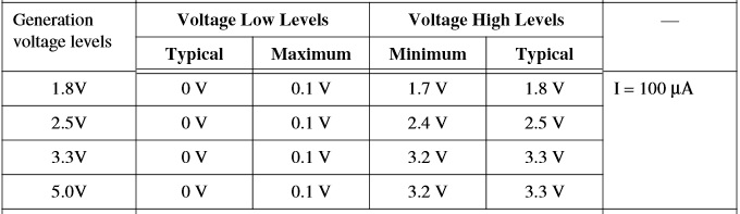
I just want to know that we can use pxi 6541 for output 5V (static and dynamic).
It seems that we can have of 1.8 V, 2.5 V and 3.3 V. But in NI MAX Control Panel, we have the possibility to 5V logic.
Any help will be appreciated.
Hello
The 6541 is a 5V TTL compatible card. Which means that the tensions it generates and uses comparisons are compatible with 5V TTL logic parts. However, the 6541 does not actually generate 5V digital signals. If you look at the table in the specificationsdefining the output voltages, you will notice that, for the value TTL 5V, voltage level is 3.3.
I hope this helps clarify what you see.
JC
-
Controller PXI-8108, causing the DMA failure
I use a controller PXI-8108 running Windows XP. I have a card PXI - 6561 HSDIO trying to DMA data to and from a PXI-808 StreamStor RAID controller and the disk. DMA reads and writes do not move correctly when this controller is in the chassis. The address is not correctly increment on the PXI bus. I removed the controller and replaced by a set of MXI-4 running from a desktop PC and it works fine. I also changed the locations a SMU chassis PXI cards and it works very well. I have checked revisions SW and them were duplicated on the PXI-8108 to match the PC and still no luck. Looks like the PXI-8108 is maybe defective. I joined configs SW of every system I've tried.
-
Installation of driver with PXI-8360 error "this device cannot start - Code 10"
While trying to install PXI-6541 to the PXI-1036 chassi with controller PXI 8360 [express-8360 side laptop], the error message "this device cannot start [Code 10]" laptop is Lenovo T60 with the latest version of the BIOS
Thank you
Manu
Sounds great Manu,
I also followed on that for you, then you should be getting approval sometimes today.
I hope for the best
-
How to read a waveform beginning after trigger conditional
Hi all
I need to communicate with the PXI-6541 card with three sons.
The installation is as follows,
The first line is the trigger line. I need to wait until they get front down.
The second line is the active signal line which is the card output line. I need to make this high with a certain delay line when I get the trigger.
The third line is the row of data that I need to acquire by waveform playback.
The problem is that when when trigger strikes, it begins to acquire waveform data, I need to filter later because valid data, it is only when the active signal line is high.
So I want to get rid of data filtering.
When trigger hits, data acquisition must wait an active signal to go high. Once he should start the acquisition.
Thanks in advance...
KAMRAN
KAMIJI,
Unfortunately, you will not be able to run different generation and acquisition to two clock frequencies without using an external clock any. If you look at the help of HSDIO Clock Sources summary , you will see that there is only one clock available onboard. If you need to acquire half of the rate, you will need to provide your own clock that runs at this rate. Now, you could take the clock generation and export this clock CLK ON DDC CLK or terminal TO terminal, and then use some external circuits divide the clock frequency in half and then import the clock signal in the STROBE line.
Another option is to use a data line, and simply write a 1010101010 model. This would actually give you a clock signal which was half the rate of your generation on a row of data session and you could then this wire channel to the CLK or STROBE line and use it as a clock. It would take just allows you to use a channel more digital output.
I would like to know if you have any questions about my suggestions. Thank you!
-
How to control each channel of the signals emitted by the generator of digital waveforms?
Generator has digital waveforms of 8 channels. I need to generate two different signals for HSDIO. How to change and control two different ways? In addition, how to translate pinout of the PXI-6541 to channels? I need pin 1,3,29 and 31 control signal individually.
Thank you!!
You need to combine your personal data in a table. The digital waveforms is simply a numeric representation of the binary table. It always boils down to bit 0 of each element of the array will channel 0 (or the first string that you specify in creating dynamic channels). The next bit goes to the next channel. My last post is very clear. To display the table in binary, right-click on a table element, then select the display Format, then select binary. You can also right click on the element, select Visible, then select Radix Show to display the small b before the number. One last thing, in the display Format window, uncheck the box next to the minimum field width to use. Then set the digital just below zone 8. Then select Pad with zeros to the left in the box below.
You should not use waveforms up to what learn you more about how the HSDIO operates on the input data. It is not difficult to combine waveforms, but it is not as clear as it is using an array of U8, U16 or U32.
Trying to explain further. The first number to be written to the HSDIO will have this effect: Bit 0 (LSB) of the number is written to the first HSDIO string you specify. Bit 7 is on channel 8, you specify. If you specify no 8 channels, the bits download ignored. If wiring in a certain number will produce only a single bit on each channel. In other words, the number has already combines the bits of all channels that you specify. Combine you do nothing yourself. Return to my photo on my last post. By wiring in a table, you cause a binary model must be generated.
I hope that is more clear.
-
NIMax.exe - Entry Point not found - attempt to create the task in MAX
I have two different cards using NOR-DAQmx: PXI-4461 and PXI-6259. They are installed in a PXI-1031 chassis with a PXI-8105 controller. Both devices pass their self-test in MAX. When I try to create a new task for either, I get first the expected selection dialog box:
Once I selected "Analog Voltage" (or anything else), I get the following error:
Last week I upgraded my to a PXI-6562 HSDIO driver, who led me to update NOR-DAQmx to 9.2.3 and repair the two installations of Windows to get their work (see this forum thread).
Creating task used to work. The system always recognizes one of the tasks I created there are weeks for the PXI-4461.
Here's a screenshot of my current versions of software:
Does anyone know how to fix this?
I solved this problem by downloading and installing the driver OR DAQmx 9.3.0. This, in turn, has caused the problem of the post I linked above, which I fixed it by choosing 'fix' in the control panel to 1. the HSDIO driver, then 2. the NOR-DAQmx driver. The order of the questions. Now, it seems to work.
-
Hello
I'm using Labview 8.6 on a PXI-1045 chassis, a synchronization PXI-6653 module, and a PXI-6552 HSDIO module.
I want to use the CLOCK out of the 6553, but I can't find the Subvi PXI - 6553 NISYNC.
Where are the Subvi NISYNC?
I did a search for OR SYNC on the range of functions, and they aren't there.
Thank you
Roger
I don't have the NO-SYNC in the Labview function palette, as show you.
I already did a computer shutdown and restarted the computer after the installation of NOR-SYNC, and still there is no sub - VI NOR-SYNC in the palette menu.
I'll try to uninstall OR-SYNC and re - install OR SYNC from the link you provided.
Thank you
Roger
-
I'm using LabVIEW 2010 and installed the drivers from device LV2010 and try to use the HSDIO functions, while setting the HSDIO function on the block diagram showing niajel.dll is missing, can someone help me fix this bug.
I tried to uninstall and install not able to set several times.
Hello. niajel.dll corresponds to the NOR-TClk, although NEITHER-HSDIO does not specifically use it. You use certain functions TClk?
Also, what other PXI device driver are installed on the system? Could you give a report on the MAX system?
-
Dear community,
I am trying to implement a background basket (software) PXI trigger on a chassis NI SMU-1082 with LabView 2015 (32-bit) running on an SMU-8135:
HS-DIO (SMU-6544) in slot 2,
-Acquisition of data (SMU-6363) into the Groove 4,
-Flex RIO (SMU-7962R + OR-6583) in the Groove 3.
The trigger schema is explained in the attached file ' LV-PXItrig-HSDIO-DAQ - overview.jpg ".
Scenario 1: written DAQ analog signal and sends signals trigger HS-DIO (software) through bottom of basket, after East of waveform of the complete signals to DAQ for acquisition.
Scenario 2: logical impulse on an external port HS-DIO triggers signals HS-DIO, after HS-DIO waveform is complete DAQ triggered for the acquisition of the ADC by the backplane.
In principle this breaks down to send a trigger of module A to B by PXI backplane. The SMU-1082 chassis has a bus trip with 8 lines (PXI_trigX, X = 0,..., 7) more a trigger in Star controlled the slot 2.
I've linked to implement a software trigger, but I can't access the refreshing resource and execution, see the attachment. Other ways of implementation including the DAQmx Terminal / routine disconnect Terminal have not worked for me either. I am aware about the connection of trigger using the node property VISA but I can't make a trigger.
Tips, comments or solutions are appreciated. Thank you!
For scenario 1, you want to trigger the HSDIO acquisition to begin as soon as the analog output DAQ starts? You can use
DAQmx Export Signalto send the trigger for the start of one of the lines from the Trig PXI backplane. Then, you need to configure your HSDIO acquisition to use a trigger digital beginning on the same line of trigger. Take a look at the example of the "Dynamic hardware generation start trigger" in the Finder of the example (help > find examples)For scenario 2, looks like you do a dynamic unit HSDIO generation when a digital trigger arrives on one of the PFI lines. Once the build is complete, you want to send a trigger for the DAQ hardware to begin sampling. If this is the case, you again use a trigger to start material in your task of NOR-HSDIO, as you did for scenario 1, but use external trig line as the source, rather than the bottom of basket. There is no case of material when the build is finished, but you can use a marker in script mode event instead. The example of the Generation with dynamic event marker' in the example Finder gives a good starting point for this type of operation. You'll want to set the output terminal for the event to be a line of backplane trig, and then tap the DAQmx to start on the same line trig trigger.
-
Generate a digital waveform like memory on PXI cards
Hello
I'm looking for a way to send a large digital waveforms using a PXI digital signal generator. I saw DIO HS cards, but their memory is smaller than the files that I want to transfer. My understanding is that the PXI backplane bandwidth 132 MB/s. So, I shouldn't be able to stream a digital signal from the memory of the card that is slower than the CPU? For example, 50 Mbits / second (equivalent to only 6.25 MB/s)? However, I think I understand after reading their textbooks is that you cannot continuously transmitting a large waveform of the processor memory file, you must transfer the file to the memory of Council first and then transfer that out.
Does anyone know if there is a way to have a flow of digital signal generation card an arbitrarily large directly from memory to the processor of digital signals? Or, what is the fastest card of pxi digital signal generation that does not require the storage of Council first files?
Thank you
Isaac
Hello Isaac,.
Take a look at the following area developer.
NOR-HSDIO Stream from disk (generation) using Win32 file IO
Note that you will not be able to take full advantage of the maximum rate of update HSDIO devices, because the data must be transferred in a bus. Some other considerations are the width of the data as well as the HSDIO device you select, which may depend on other requirements not related to the size of file or waveform (for example the standard voltage or whether you need hardware compare). For more information, take a look at the developer following items area.
Data streaming of Architectures in the PXI systems
The use of National Instruments Logic Analyzer and generator of test patterns SolutionAdvanced features of e/s high-speed digital devices White Paper Series
-
HSDIO - deterministic written submission during the generation
Hello
I use a card HSDIO (PXI-6542) to control a device (DUT) with a predefined fixed length, waveform continuously running.
That maybe had TO actually benefit from the dynamic changes in digital signals according to the measurements on the INSTRUMENT itself.
At the moment I just pass off the coast of the ASE and map HSDIO, write the new waveform on the map, turn to ESA and the generation of digital signals.
Of course, this is not optimal and I would like to change the way signal 'live', while the DUT is running.
Just crush a waveform, whereas it is generated should not be working smoothly due to a condition of race as explained here: http://digital.ni.com/public.nsf/allkb/14CE41C9CB9F10A88625766A005CEE47
I think that I've found a workaround, but need a confirmation about this.
Instead of just a waveform, I could use 2 and select which is generated using a trigger.
The corresponding script might look like this:
script myScript

  Repeat forever

          If scriptTrigger0

            generate a waveform1

          on the other

            generate a waveform2

          end if

  end repeat
For example, the idea is to generate a waveform1.
Then according to that CSA should I calculates waveform2 and transfer it to the HSDIO map.
I think here is overwrite waveform2 with the data of the same size will not create any small problem because it is not currently used to generate signals.
After this using the trigger, I could start using waveform2. If I need additional adjustment of wave shape I could do this by editing waveform1, so it is not used for the generation and thus now alternating serves really what waveform.
Am I correct in that a waveform in memory but are not currently used can be replaced without causing glitch on an another waveform that is currently?
Kind regards
Baptist
Hello, Baptist,.
Yes, you are right. It is a method to dynamically change the waveforms on the fly that was already used in the past. If you waveform1 to generate and download waveform2 then it is idle, it will not affect the generation of waveform1. Then, triggering via scripttrigger to waveform2, then you can download the next waveform, you want to use for waveform1 without affecting the production of waveform2.
-
2515 PXI to wired, and correct connection to GND
Hi all
I am interfacing Board (DIB) test of switching pxi-2515. The switch will connect PXI-4130 EMS & PXI - 6552 to ESA to characterize several tests.
I'll use the connector VHDCI 68 pin on my Board to connect to via a NI SCH68-C68-D4 cable 2515. I will not use all channels of the ESA. Based on the schema of pine http://zone.ni.com/reference/en-XX/help/375472A-01/switch/2515_independent/#MakingAConnection ; How can I connect right connection GND pins to my connector on the Board?
I'm a little confused, should I connect all pins of MASS to the land of my Board? Or can I choose some GND pins to connect to the land of my Board of Directors (since I will not use all channels of OTC in the 2515 - i.e.do some GND pins have chandres with some pins had?)?
The left plug in 2515 is connected to pin right connector (which connects to the DUT) PXI-6552 DI/O. would be GND be referenced to GND via left connector (through the land of 6552 system)? Or should I always connect everything to my land of the system HAD?
I would appreciate any clarification!
Thank you
Saami
Hi Sami,
The PXI-2515 will share the land line between the DUT and the card HSDIO when you use the GND lines. All GND pins share the same physical terrain, so it shouldn't matter what PIN you use for each channel. Just make sure you have each HAD the ground connected to the GND PIN. There are usually several distributed through the connector simply GND pins for easy access on the ground of several channels without having to connect multiple threads in an earth pin.
Which is better?
Hope this helps.
Chris G
Maybe you are looking for
-
Cannot load a site Web of Firefox only, other sites work.
This used to work, but now I can't connect to a server by using Firefox. I can connect to this server using Epiphany on the same laptop and other computers, even using Firefox on other computers (although this system has not yet upgraded to FF10). Th
-
Hello people, As part of a network, I have a few switches out and about. The road is like Yes, > 8 port router > 8 port Modem SW, SW, SW 5 port 5 port. Use the uplink ports to provide communications between the router and switches? I read here and th
-
Eliminate the prompt at startup to sign as an administrator or guest in Windows Vista Home Premium
I write on behalf of a client. The customer wants to know how to remove the prompt at startup to sign as an administrator or guest in Windows Vista Home Premium. I hope to hear from you.
-
Hello I need to create a new Visual Style for Windows 7 that will be installed on the client systems as part of Symantec's Ghost Image. I read that the custom visual style must be registered with Microsoft. Does anyone know the process on how to reco
-
Get 4 disk error when booting from a CD on Windows 7
Having a problem starting at a BIOS from a CD on my Inspiron E1505 laptop. With the help of Windows 7 Professional. Don't know why, it should work... I have it set up correctly and everything to boot from the CD player, here is the problem: ISOLINUX