OR PXI-7853R memory block
Hi all
How to set up a memory block maximum size on my FPGA target and what size of memory allocated?
The Documentation States:
NI PXI-7853R : built-in memory 384 kB
Short form : block Embedded RAM 3 456 Kbps
384 k = 393216 bytes
3456 kbit = 432000 bytes
What is the problem here?
Memory project FPGA Configuration dialog box
DataType U8
"Asked the number of items": maximum of 4294967295 (stays of value even if you enter a higher value, seems to be a 32-bit overflow)
Number of items: 134217728 (no idea what means the number).
I'm just assuming that 393216 or 432000 is the maximum. number of bytes?
Finally, there is a build error (error of xilinx) about the size of the ram, if the number is higher.
However if there is no error (for example using 393216) generation (usually 10 minutes) proceeds ' generation xilinx ip "within 15 minutes.
I don't want to continue to guess, then, what is the number I enter the memory maximum memory Configuration dialog box?
Concerning
Christoph
Hello ChristophSauter,
The maximum number of items that can be created in one memory FPGA PCIe-7854R card when you use U8 is between the 442368 elements and 393216 according to optimizations that Xilinx LogiCore block memory generator Minimum area algorithm can do.
The cylinder block Embedded is 3456 Kbps-> 3538944 bits
But it is continue to know how many ram blocks block exist and what data you want to write in memory, it is possible that the 8 bits of data use 9 bit in memory. Overview of the Virtex-5 familypage 2 XC5VLX85 is the FPGA and the information on it.
I hope this helps.
Tags: NI Hardware
Similar Questions
-
How does impact FPGA FPGA memory block size in compiling?
Hello
I'm working on PXI-7841R cards and I would like to know how can I determine the "maximum number of items required" of the memory block and it is better to work with different blocks of memory or a single...
Is it better to add several blocks of memory of the small number of elements... 1024 for example
or 1 memory block with (let's say I have 10 signals to generate) 10240 items?
I started by following OR example:
http://www.NI.com/example/26548/en/
I want of preferring several blocks of memory to facilitate the reading of memory block in a loop with a loop index as the address For!
Vincent
How about you post the code so that we can have a look. Keep in mind that the FPGA target you use doesn't have a lot of resources.
How wide is the data in your booth? FPGA Virtex 5 supports either 18 or 36-bit width. Wider widths require several booth to get data in and out, even if the use is shallow. In addition, each BRAM can handle at most 32768 Bits (not bytes) then train your width times your depth, you can calculate how much BRAMs, you will need.
Examples:
depth width x 65536 32 bit using 64 BRAMs (1 * 32 * 65536 = 2 Mbps, 2 Mbps / 32 kbit = 64 BRAMS).
8-bit depth width x 65536 will use 8 BRAMS (because the bitness is less than 18 years of age, we can use each BRAM as two independent 18-bit BRAMS: 0.5x8x65536 = 262 Kbit, 262 Kbps / 32 Kbps = 8 BRAMS).
depth width x 65536 40 bits will use 160 BRAMs (bit width is greater than 36 bit, TWO BOOTH must be parallelized to deal with the width of the Bit: 2 x 40 x 65536 = 5.2 M, 5,2 M / 32 kbit = 160 BRAMS)
In view of the fact that your FPGA has only 32 36 bit BRAMS (or 64 18 bit) then you must ensure that your data will be fit. The maximum width bit supported by this goal for 65536 depth is 16. This figure will be smaller because some of the built-in features actually (DMA transfers and so on) are already using one or two BRAMS.
-
Use the PXI-2630 terminal block in a matrix configuration?
My apologies in advance for the length of this post!

I use the PXI system with PXI-2530 switch modules, related to a series of USE with PXI-2632 (1W matrix 8 X 16) connector blocks and a PXI-4071 DMM for each switch module. My request, uses the PXI system for measurement of current and voltage external to verify and/or benefit from restraints of reliability. A requirement of the application, therefore, is that there must be a ride from DC through each USE with change of the minimum impedance as the application between its "bypass" mode switches and its mode 'measure '.
I used this Setup with connector blocks of matrix in conjunction with one of our test systems, and I am satisfied with the results. I started working with the Test System, has no easy connection to catch HAD, I needed to build a kind of interface the PXI system and a resistive faced load HAD, it was not difficult to build in the wires that attach to the Terminal screw of the 2632. He did turn into a nest of a coded son rat I did my best to keep clean and tidy in different bundles, however. Fortunately for the cable fasteners!
My next task is to use this application with system B Test, which has an interface of pines buck header with which each signal that goes to or from the DUT can be obtained. No welding or pass the wires through the openings where the designers have no intention of son to be stuffed. I intend to build a break-out Board that allows simple connections between the modules PXI and the number of Test B system which we have or will have in our laboratory. In order to simplify the configuration/installation, I want to reduce the number of connections to terminal block screw. Preferably, I would like to completely remove the screw terminals and use lever-based connections where I can't have mating of the headers. The PXI-2632 terminal blocks unfortunately use Terminal screw.
In matrix mode 8 X 16, the closing of the PXI-2530 switch kcom1, 3, 5, 7, no matter what points in the array are connected. A link between the row of right and column C is done by closing the switch corresponding to k (16R-C). I checked using the Soft Front Panel.
I also have a number of connector PXI-2630 blocks. These are intended to be used with the switch module in one of its MUX modes and include 8 banks of connections of the header 2 X 9 pins. In the the 2530 documentation and 2630, I identified that switch k-x is associated to chX output pin, ch0-15 related to the pins 1-16 from Bank 0, C16 - 31-associated pins 1-16 of Bank 1, etc.. X = 16 B + P-1. PIN 18 of each bank is used for independent MUX topology comX. Pines multiplexes sixteen seem to correspond to the sixteen columns of the matrix, with eight common lines corresponding to eight lines.
Here's what I would do, but I would like to ping the forum to see if anyone tried something similar and wisdon to share the thought:
- Make custom cables which connect the pins 1-16 of all eight banks 2630's header with a single Ribbon connections 16 son carrying the signals emitted by the interconnected banks (poles!).
- The custom cable bundle will also include a wire connected to the pin18 of each of the eight banks (line connections!)
- 24 total wires in the harness will end in the header connections who will probably partner by the lines that I currently connect to each object to be measured.
- Make additional harnesses that interface with the Test System B header pins.
- Make a map of derivation using band Council or a similar material to provide header pins to connect the two above custom cables and allow the connection of other elements such as resistors using Terminal level.
I checked this concept using the Assembly of 176 pins four terminals, like a bunch of little pieces of wire and cable. Are there other issues that I have to configure, such as the elements of a terminal that establish physical components of the switching topologies? The bowels of the PXI-2632 provide more features than the interconnection of the sets of eight sixteen pins? The bowels of the PXI-2630 connect elements that do not allow my proposed scheme?
I appreciate the suggestions and all entries!
Thank you
Jeff Zola
Hi Jeff,
First a correction to my previous post: 2632 Terminal has no reed relay protection resistors as I said earlier. The resistance that you were referring to the 2632 and those that I confused, is there to connect the columns of the switch. Resistances have a resistance value zero and act as the electrical connections. The 2632 connects columns c0 to c16, c17 c1, c2 to c18 and so on. Switch cards 2531 and 2532 have the protection relay reed on board resistors.
As for resistance in the map that protect the reed relays, they are generally very low and do not significatly affect even small tensions that pass through the switch. The resistance won't affect all currents in the map. Any effect that the resistors have on tensions will be with the precision of the switch card specifications.
Thus, to address the other issue in your post, there is no resistance in the connectors because they are not necessary.
-
How to dispose of the memory blocks?
Hello
How to dispose of the memory blocks?
Thank you.There are many places in the memory where the blocks are kept. So if you want to say, 'data buffer cache' that the command would be (10g).
alter system flusher buffer_cache;If you meant shared pool
Alter system flush shared_poolHTH
Aman... -
Out of bounds (beyond the end of the memory block) pointer argument
Hello
I write a program to control the power supply. One of the functions is to set the voltage and current in the table.
When I run it, it displays the following error message:
"Off-shore argument pointer (beyond the end of the block of memory) '
Could someone help me with this?
Thank you!
This function code is as below:
int CVICALLBACK SetValueCallBack (int, int int event, control panel,
void * callbackData, int eventData1, int eventData2)
{
switch (event)
{
float Voltage_Set, Current_Set;
int TimeSet;
int lines;
char VoltageSetBuff [30];
char CurrentSetBuff [30];
case EVENT_COMMIT:GetCtrlVal (panelHandle, PANEL_SETVOLTAGE, & Voltage_Set);
GetCtrlVal (panelHandle, PANEL_SETCURRENT, & Current_Set);
GetCtrlVal (panelHandle, PANEL_SETTIME, & TimeSet);
GetCtrlVal (panelHandle, PANEL_SETROW, & RowSet);
sprintf (VoltageSetBuff, "%2.2f", Voltage_Set);
sprintf (CurrentSetBuff, "%2.2f", Current_Set);
SetTableCellVal (panelHandle, PANEL_TABLE, MakePoint 1, lines, VoltageSetBuff);
SetTableCellVal (panelHandle, PANEL_TABLE, MakePoint (2 lines), CurrentSetBuff);
SetTableCellVal (panelHandle, PANEL_TABLE, MakePoint (3 lines), TimeSet);break;
}
return 0;
}I am able to reproduce the problem, if I see the problem on the line just before the one you mention. I think it's probably because the variables declared inside a switch statement before the case labels are not initialized the same way as other variables are.* If move you these variable declarations before the passage, I think you will find that your mistakes disappear:
int CVICALLBACK SetValueCallBack (int, int int event, control panel,
void * callbackData, int eventData1, int eventData2)
{
float Voltage_Set, Current_Set;
int TimeSet;
int lines;
char VoltageSetBuff [30];
char CurrentSetBuff [30];switch (event)
{
case EVENT_COMMIT:...
I'll file a bug report to make sure that this gets more studied.
* Note that the rules of the C language, even initialization explicitly (for example int TimeSet = 10 ;)-this position inside the switch has no effect!
A. Mert
National Instruments
-
ProBook 6440 b: Probook 6440 b memory block
I recently bought a HP Probook 6440 b (refurb), only for the purpose of trying 10 windows.
The first thing I did was replace the puny 160 GB HARD disk with a 1 TB HARD drive and buy 8 GB RAM to replace the cam laptop with 2 GB of RAM.
After Installing Win 10 and the upgrade of memory, I noticed that my usable reported memory is 2998 8192 MB MB.
Making a few arround to dig, I learned that it is because my laptop, while the solid case is below on the Department of BONE.
Belarc shows 2.53 Core i5 M540 64-bit ready Multi-Core system (2 in total) and type hyperthreading (4 total)
However, from what I found, the 32 bit OS, is to limit my memory to 4 GB total!
So my quesition is as follows. Is there a solution?
I would get all of the 8 GB (or at least more than 2.93). Is this possible without a major disassembly? Also, from my research, I think that the reason that the usable memory is that only 2.93 GB is because I have an integrated graphics (GPU) which is aspire little memory.
Don't know if I can come back 1/2 of a 2 stick memory package, so this may have been a lesson in "read-twice, once arrested.
You are the very welcome.
The steps you described are quite right — and Yes, all data will be lost, so I would not invest a lot of effort to do something else until you get the discs.
If you order by regular mail, the load is about $10 for the scope of delivery. I usually get them within a few days.
I don't foresee any problems.
There is a full set of W7 64 bit drivers on the support page, and there should be no difference in the W10 x 64 conversion.
The only difference will be that Windows must be able to "see and use" almost the total amount of memory you have installed.
There may be some memory reserved for the video card if your laptop is the Intel integrated graphics card.
You will have to start from the W7 x 64 disk operating system in order to install W7 x 64. It will run from the 32-bit Office.
-
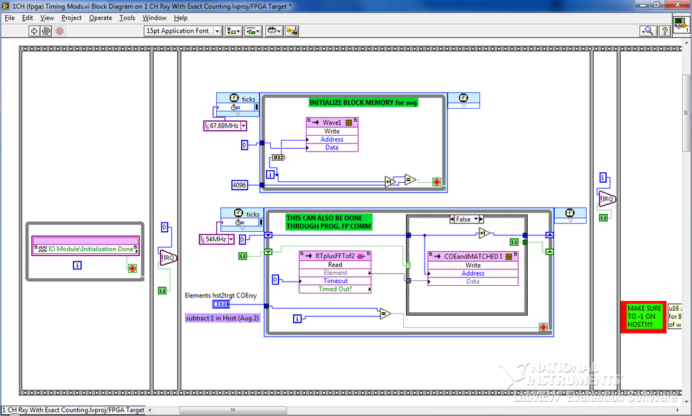
I would like to reset my memory block to all zeros (only once) using the FPGA code. In my past experiences, it did not by the FPGA e/s 'IO done Module\Initialization' NŒUD. To compensate for this, I used a SCTL that passes through each address of the memory block and stores a zero. The approach works fine, but I want to save space since we will quadruple the size of the code in a few months.
FPGA: 7954r
I/o module: 5761r
Thanks for the research!
Hey Denn_Mann,
You should be able to set your memory to initialize to zero in the memory properties. Here is a link that should help you:
http://zone.NI.com/reference/en-XX/help/371599G-01/lvfpgadialog/fpga_define_memory_db/
Hope this Helps,
Doug B
-
FPGA block memory and Timing FIFO
Hello
I am trying to access the data of the memory block and a FIFO, both having an equal number of elements.
I'm trying to access the data must be coordinated with the waveform of a block of Xilinx, I use to deal with the elements of the FIFO and the memory block.
My block of Xilinx has a 3 clock offset cycle and one without a clock cycle lag, which can lead to my use of knots of late.
My question is, the output of an element of a FIFO occur in a clock or a clock set cycle? Also, I am aware that there is a delay of the output clock cycle
block of memory to hold data into account initial reading, which will lead to my choice of offset of 3 clock cycle. Just a handful to decide how much to delay the nodes to use.See you soon
Hi RichieA
If the function or if it is a FIFO, or a memory block is inside the recycled then timed loop function and of all that is on the inside must be executed in a heartbeat. Don't forget that when you compile you are actually programming and connect a gate array so when the compiler is running, it will try to create the FIFO or memory to be executed on a tick. If this is not possible, you should get an error in NI LabVIEW or in the compilation process. Here is a link with more information.
Single-Cycle timed loop FAQ for the LabVIEW FPGA Module
Concerning
R. Esteban
-
problem with a block of memory in labview 2009
Hi all
I have "ERROR: MapLib:979 - LUT4 symbol" during the compilation process (lots of errors like this), and I discovered that the reason of my problem is block of MEMORY.
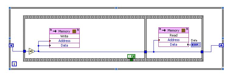
To be sure that the problem is in this block, I did a very simple project in LabView 2009 (on FPGA Target PCI5640R) only with the use of this block you can see in the photo, as well as in file test_memory block.lvproj attached link: https://www.dropbox.com/sh/u87f1oihelmm4dq/Jo_6-bICSf
I have a problem with compiling VI with this block, and I have so many errors like:
ERROR: MapLib:979 - LUT4 symbol
"window/Thatcher/n_00000036/nSCTL_00000013_00000014/n_000000A3/cOutLoc<0>1.
(output = window/Thatcher/res000001ed_wi<2>) is the input signal
"window/Thatcher/res0000020d_wo<1>" that will be deleted. See Section 5 of the
Map a report file to find out why the input signal will become conveyors.or
ERROR: MapLib:978 - LUT4 symbol
"window/Thatcher/n_00000036/nSCTL_00000013_00000014/n_000000A3/cOutLoc<23>1.
(output = window/Thatcher/res000001ed_wi<25>) is an equation that uses
input pin I2, which no longer has a connected signal. Make sure that all the
the pins used in the equation for this LUT are signals that are not cut
(see Section 5 of the report file map for details on which signals were
adjusted).Entire report, you can see in the file report.txt on the attached link.
I would appreciate if someone could take a look at my problem with simple project and suggest me a solution.
I'm really stuck with my biggest project which need to have this memory block.
I'm looking forward to hear from you,
King looks
ING. Damir Hamidovic
Hi all
I find a sollution to my problem.
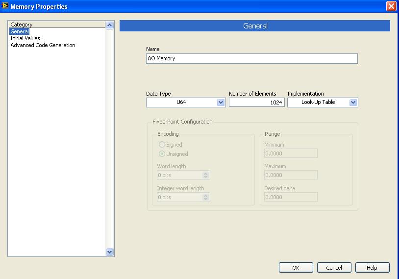
In memory-properties-general-setting up, I changed the block to look up Table memory, and I compile memory.vi and run it successfully.
I did change as you can see on the picture:
Just, can you tell me is it all "bad properties" and limits the use of this type of memory (Look up Table) of the implementation?
King looks
-
How to access memory on the PXI-8106 controller
I am able to write and read the brief on PXI-8106 using FTP functions in labview. But I'm not able to find a way to delete data that I wrote (PXI-8106) memory. Y at - it an easy way to do it.
Thank you
Kitenge
Kitenge,
Is this something you want? - Delete the file from the server FTP using the Internet Toolbox
-
Coregen memory when you use defined VI block memory
I currently have a problem when you try to compile a VI for my card Flex RIO (SMU-7965R). I have a sub - vi which contains a small instance memory set by VI (U16 X 256 elements) and a block of DSP48. This VI is instantiated 128 times in the top level VI. When I set up the memory set by VI to target the block of RAM in the FPGA, the compilation process is suspended during the generation of the nuclei (memory after ~ 45 min). LabVIEW treats each instance of as single block memory when executing coregen? I do not experience this problem when I set up the memory set by VI using LUTs. Any thoughts would be appreciated.
Thank you
Brian
Hi Brian,.
I believe that this compilation failure could be less related to the implementation of memory coregen, rather the memory of the way that is implemented in the lut and block memory on an FPGA. Lut are built through flip-flops and are perfect for storing information 100-300 bytes, while the memory block is segmented in a fixed size of 2 k RAM embedded. There are only a number of structures of block of RAM in a given FPGA and it seems that in your case that you use more of your resources block of allocated RAM. For example, in the 7831R if we tried to implement a FIFO in the maximum possible storage size block memory would be 81 920 bytes due to the limitation of resources.
The implementation of flip flop of the LUTs will allow the compiler greater flexibility in the use of resources in compiling because the size of the LUT is not fixed in the way that is a block structure of RAM. This is probably the reason why this LUT implementation is compiling successfully while the RAM block is not in this case.
Kind regards
Blayne K
-
Use of FIFO memory on two areas of clock (Labview FPGA) block
Greetings!
I'm developing an application on the FPGA of the vector signal OR 5644R
transmitter/receiver. I have two loops single-cycle timed: a 40 MHz making a convolution
and writing a FIFO memory block and the second at 120 MHz (sample clock)
who reads from block FIFO memory and uses the following values
interpolation...Under what circumstances is it permissible to use a FIFO memory block to transfer
values of a loop from 40 MHz to a loop of 120 MHz (sample clock)?
The reason I ask the question, it is that the compilation of my code repeatedly of not
reported the error below:ERROR: HDLCompiler:69 - "/ opt/apps/NIFPGA/jobs/J9k7Gwc_WXxzSVD/Interface.vhd" line 193:
is not declared. I share for everyone's reference, screenshots of my code which is an extension of
sample 'Project streaming VST' given in NI5644R. A brief description of attachments is
given below...
1. "Top_level_FPGA_part1_modification.png": in a loop SCTL 120 MHz, a sub - vi bed FPGA
go a block FIFO memory... In fact, the reading is actually made when entry
"read_stream" is activated... (see details in read_from_fifo_true_case.png)
2. "Top_level_FPGA_part2_modification.png": a 40 MHz SCTL, wherein is a subvi FPGA
called to write the output of convolution to block FIFO memory.
3. "target_respone_fpga_block_FIFO_modification.png": an output of a convolution filter is
written in block FIFO memory each time that the convolution output is available...
'ReadBlockFIFO' VI (circled in Top_level_FPGA_part1) is invoked in a 120 MHz SCTL.
4. "read_from_fifo_false_case.png": when the input "read_stream' of this vi is false,
data transfer memory FIFO of block to a different FIFO ('generation filter") takes
place.
5. "read_from_fifo_true_case.png": when the "read_stream' is set to true, the data is read in
'Filter generation' FIFO and spent on the chain of later interpolation to the
120 MHz SCTL...
I hope that the attachments give enough clarity to what I'm doing... If we need
For more information, do not hesitate to ask...
Kind regards
S. Raja Kumar
Greetings!
I think I understand the problem... The error probably occurs because a DMA FIFO
(FPGA host) is playing at 40 MHz, and it is checked for the number of items in a loop
120 MHz... It is not captured by the "pre-processing" by the labview FPGA, but by the Xilinx
compilation phase synthesis tool.
A lesson I share, is that if you observe this kind of problem, watch if there is incompatibility
in the areas of the clock to access a FIFO...
Kind regards
S. Raja Kumar
-
I had some strange crashes recently on a no. 2851.
When you check the crash logs, I found that the crash was due to a wrong address (supported or fetch statement) an exception.
The exception occurs at the same address every time.
Is there a way to isolate this block of memory for active memory / mark as unusable so the system tries to read?
The memory module on the 2851 replaceable or is welded in the Mo?
Hello
No, you cannot isolate/disable the memory block and refrain the router to use it.
the memory stick is replaceable on its expansion DIMM location:
http://www.Cisco.com/c/en/us/TD/docs/routers/access/2800/hardware/instal...
http://www.Cisco.com/c/en/us/TD/docs/routers/access/2800/hardware/instal...
but before you do this, I'd say to open a TAC case, if still under contract, to diagnose correctly that it is indeed a problem of bad memory/RAM.
-
Exactly how memory works in Labview Fpga
I use a PXI 7853 and me for the last few days I've been playing with the help of blocks of memory in the FPGA.
Now, I'm relatively new to Labview FPGA programming and this is why I would be grateful if someone could provide me with some clarification on the following points:
(a) given that I work on the development host computer when I initialize memory with the ability to use a memory initialization VI then how does exactly in the backend. What I want to ask is, when I change the values of the memory in the computer development and then compile the FPGA VI in the Board of Directors, what is data memory are brought in the FPGA. If this is the case then in what form are the details initially registered in the development computer.
(b) is it possible for me to use the initialization method VI to change memory n valuesi while the FPGA VI is running. If this isn't the case, then it would make a difference if I stop the VI and then change the values using the Initialize method. Who would actually reflect on the FPGA or should I have to re compile the FPGA VI whenever I change memory values in the development machine, using the "VI initialization method (which is available as an option for us do a right-click on the block of memory in the Project Explorer window).
I tried test with simulation of FPGA VI and found that when I try to change the values of memory by running VI initialization. a pop up that says that it is not possible that the FPGA VI is still in service is delivered.
Any light on this or advice with links would be much appreciated
See you soon
sbkr
sbkr wrote:
(a) given that I work on the development host computer when I initialize memory with the ability to use a memory initialization VI then how does exactly in the backend. What I want to ask is, when I change the values of the memory in the computer development and then compile the FPGA VI in the Board of Directors, what is data memory are brought in the FPGA. If this is the case then in what form are the details initially registered in the development computer.
When you compile the FPGA VI, he will understand the values used to initialize the memory.
Are asking you what happens if you run the VI FPGA on your development computer, and your FPGA VI, written in the memory block, the new values are included when you compile the FPGA VI? No, these values will be lost. The values contained in the bitfile are the values you used to initialize the block of memory, as defined in the memory properties dialog box. The initial values are saved in the LabVIEW project file and the definition of memory block.
sbkr wrote:
(b) is it possible for me to use the initialization method VI to change memory n valuesi while the FPGA VI is running. If this isn't the case, then it would make a difference if I stop the VI and then change the values using the Initialize method. Who would actually reflect on the FPGA or should I have to re compile the FPGA VI whenever I change memory values in the development machine, using the "VI initialization method (which is available as an option for us do a right-click on the block of memory in the Project Explorer window).
You will have to recompile the FPGA in order to use the new initialization values, because these values are part of the bitfile FPGA.
-
Help with PXI OR 4070 DMM and OR PXI MUX 2501
Dear alls,
Sorry to post a simple question, but I couldn't understand it.
My PXI1033 chassis has NI 4070 Flexdmm and NI PXI MUX 2501, block of connection OR-TB2605, 1 thread by MAX-mode configuration.
I'm trying to measure 3 voltages (from 2V to 5V) by connecting them to ch0, ch1, ch2 MUX2501 (Terminal screw for example 67,66,65 and common screw terminal 27).
Any device passes self-test to the MAX.
I then use NOR-DMM/Switch Express, swap the added devices and also scan list.
Trigger is PXI; Handshake (PXI trigger 0 and 1 PXI trigger)
However, I could not measure all the signals.
I also try with other examples in LabVIEW help, but have still no results.
Am I missing something?
And, although the trigger section is very clearly explained, I have no idea how the DMM to run his measure through switching and multiplexing. How DMM connected MUX?
I noticed that the DMM and the switch share the same trigger bus (two of them bus trigger 1), but their local buses are different (DMM: local bus left/right = 2, 4, and buses premises MUX left/right = 3.5)
Your advice is much appreciated.
Thank you.
Van.
Lonestar thanks!
Maybe you are looking for
-
NB305-105 - FN keys do not work after installing Windows 7
Hello I'm trying to install Windows 7 64 bit ultimate in netbook Toshiba NB305-105, I have install all drivers, but I can't solve the problem with the WIFI. In particular I don't found drivers for the special key FN to switch on the WIRELESS card.I t
-
Power on the L750D Satellite problem
A problem with the power. Computer is turned off. Tried to restart, but the screen flashes.Battery power ran good until told to look for the ALT powerAfter plugging it back into the wall started to blink.
-
I use the mail account on my i - mac (using el capitan). My recently changed email provider the port 587; It was 995. My outgoing mail won't. I use another service for incoming mail that is not affected. Any ideas on what could be the problem?
-
I often get the message "error running...". The program was asked to stop in a unusual way. "My computer stops and I lost everything I do. What's wrong?
-
Printing problem with my HP c310a (on wireless network now) MacBook Pro 2012 Maverick
Like SingingDixie, I sent 4 messages in January 2014, not being able to print from our MacBook Pro with Maverick OS 2012 on our network, a HP c310a printer, but I don't see that I got all the answers. This printer is on our network as it is Our HP c3