Output 2 signals of pci 6713
Hi guys,.
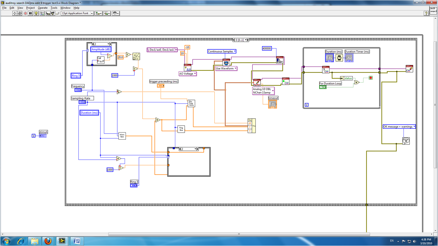
I tried to program my card analog output PCI 6713 to the output of the 2 signals, AO0 one and the other of A01, but I get this error message:
DAQmx Write (analog 1-d Wfm NChan NSamp) .vi:3
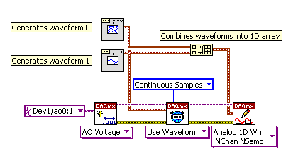
with error code:-50103 I have attached my code for your perusal. Help, please Ridwan All you had to do was select the two channels when you all first created the DAQ Assistant and combined the two signals. With the existing DAQ Assistant, you can add additional channels. I recommend that do you some review of the information available in the getting started with DAQmx Tags: NI Hardware Time to update buffer PCI-6713 Hello guys,. We use PCI-6317for 50 Hz generation of waveform of 3 phases for a quite a while using the library OR-DAQ traditional. We could not get a reliable update of a waveform with a single call to the WFM_DB_Transfer function and need to call double. For now, that's a good solution, but now we have different requirements. We went to NOR-DAQmx and surprisingly managed to update the PCI-6713 buffer with a single call to DAQmxWriteAnalogF64. But it seems that we can update the buffer only once per period of output signal. That is the first question. If the answer is positive, how can it be done? I have attached a LabWindows CVI 7.0 source code for an example of test (for 1 channel only) program we wrote specifically for this post. Could someone kindly tell me what changes to the code have to do to update the asynchronous output with output buffer? And another question. Thank you very much for all supplied glue! Andriy The answer to this question is no. It is not possible to dynamically change the environment buffer output. You must wait until the buffer is exhausted, and then change the stamp on the next set of data. The only thing to do with your current hardware is to reduce the size of form of wave/buffer. You must call the function write significantly more often, but you can change it to any of these points. Also, get a reliable 3ms response in your software feedback loop will be entirely dependent on the speed of your computer. If Windows decides it must allocate resources elsewhere (automatic update check, MS Word being opened, Media Player, play music), then the program CVI can certainly lag. That's why he could miss the update of buffer, which is probably the reason why you get the error 200290. The code cannot run fast enough for all process before the depleats buffer. The absolute best thing to use to control is one of the FPGA modules. With them integrate you actually in the material you want your control algorithm to be. This means that the control algorithm is all timed material, producing the best possible response times. What rate are you inputing to the sampling frequency? In addition, in the code you sent that you send "fFrequency * SAMPS_PER_GRID_CHANNEL" to the DAQmxCfgClkTiming function. I wonder why you're multiplying your frequency of SAMPS_PER_GRID_CHANNEL. The rate input parameter must be just the frequency in Hz you want items to be generated at. There are two cards I have installed on this computer. The two cards are PCI-MIO-16-4 & PCI-6713. They all have two cable connecting to each other on top. The current operating system is Windows 7 64-bit with 4 GB of memory. I went to the drivers OR support and typed in the serial number for these two cards. The two cards came back with the same drivers. That is NEITHER-DAQmx Base 15.0. Installed the driver NOR-DAQmx Base 15.0, but shows Device Manager always the exclamation point on those two cards. So, I tried to search for new hardware and get a message saying cannot install driver. I also tried to restart. Help, please. Thank you hms168 Drivers install successfully. Thank you! Continuous 5V output and signal of Stimulation at the same time Hello I'm out a constant signal to 5V to power a testbed and output a signal of stimulation (create a small magnetic field, etc.) at the same time. I try to use DAQassistant with several output channels, but I can't fix an AO0 data set and the other set of data in AO1. Please notify; my code is up to this home. Thank you! Emily Many DAQ cards provides a constant voltage of + 5V output. DAQ hardware do you use, and there a such output? If so, use instead. It will manage a current higher than an analog output. The analog output lines are not designed to power no matter what, they are purely for signalling. Synchronization of the signal with PCI-6602 Hello I need to generate three signals that must be synchronized. To do this, I use a PCI-6602. The first signal is used to trigger a device, the second signal is used to simulate the noise. The third signal should wear the noise so that it starts before the trigger signal and stops shortly after the trigger signal. The signals are then combined with an external logic circuit. (To see what I mean, see the first PDF). I use a fourth timer to synchronize all other clocks, but the three signals are beginning to run before starting the timer task. I have this evaluated using not to no and a oscilloscope. The trigger and gate (first and last signal) are below 100 Hz, the noise signal is about 200 kHz. At least the trigger and the door must be started synchronously, otherwise the waveform is not what we want. The noise signal didn't need to be synchronized. I am sure I am missing just a little detail here, maybe you can show me what I missed. Please check my screenshot of LabView to see what I've done here. If you want more information about the VI, I can take apart a little and send it, too. Try using start to the outputs of the 3 meter (see attached VI) constant output voltage DAQ NI PCIe-6321 Good evening I am trying to output a constant tension there 10V DAQassist. I'm relatively new to labview and can not fully use the modules of the individual drivers for DAQmx. However, I work with hardward existing on a limited budget. Change the AO writing single-channel > sample > DBL. That should give you a single value whenever you call the VI of Scripture. Also change the entry of data in a single digital control. Maybe call it voltage or something like that? You can probably remove the synchronisation screw DAQmx and the node property Regen as those who will be most relevant. A cell of 700 ohm load will draw 10 ohms = 14.3 V/700 mA, which is still well above the 5 limit my AO lines. A load cell is wired as a bridge. It is the equivalent of two voltage dividers. Without load on the output of the cell the two lines have equal tension: 5.00 V. When you have a 20 mV out of load cell tension on the two output lines will be 4,990 V 5,010 V (or 5,000 V and 5,020 V, according to the internal configuration). So your 6321 must be configured to accept 5,020 V (plus a bit of noise, mistakes and overload conditions). So, you will need to set it to 10 V range. On the 6341 (I happen to have the factsheet - the 6321 is probably very similar) which means a +/-10 V rank. Which translates a theoretical resolution of 0.3 mV. The output 20 mV full scale of the load cell, it comes down to resolution of 6 bits (6: 16). Two possible ways to improve: 1. use a preamplifier or a signal conditioner to amplify the 20 mV at a few volts. These usually have the differential amplifiers to reject common-mode 5 V. voltage They can also have hardware filters. 2. use a power supply excitement split so that the load cell is excited by the + 5V and - 5V. This puts the common mode voltage to ~ 0 V and you can use the +/-0.2 V rank on the lines of HAVE it. The resolution is then about 6 uV and the effective resolution on your signal is approximately 11 bits. Lynn Limit the audio via the acquisition of data, what is the analog output rate of the pci-6014? Hello I'm trying out audio buffers thanks to an acquisition of data pci-6014. Audio files normally have a sampling rate of 44.1 kHz, but I noticed that when I try to exit, at this rate, that I get an overflow error. I checked the datasheet and it shows a rate of output of 10 K samples per second, way too slow! This device 6014 is quite expensive but are still unable to a stereo sound output signal... ? Is there a way to bypass this limit? It is not sensible to pay $1000 one another. See you soon. I don't think there is a way to increase the analogue of rates. The 6014 is old enough. A better card and cheaper, would be the 6221. Configuration of the analog output of the controller PCI-7358 Hello world I work with the PCI-7358 during a period of time and now I need to configure the output of the controller for a specific purpose. All I have to do is turn on and turn off the output to an analog 5V DC voltage level. I use a UMI-7774 as a breakthrough. I plugged the IO of 5-8 to the UMI axis MOVEMENT and I hope to get the tension off-axis 1 of the UMI CONTROL block. I use DAC.vi to load to turn on and off this PIN on UMI. When I tried the voltage level was 1.5VDC and it fluctuates so I tried to read the voltage on the PIN and she was 3.2Vac. It was said in this DAC.vi of charge help offset values or front torque limits does not affect the level of tension. I can't understand what is to limit the output voltage level. (I tried the 32000 and-32000 for entry this .vi) If anyone can help urgently, I will be grateful... Gencer Genç Hi Roman, in MAX, you must configure the axis as the stepper motors. You don't have to worry about the type of comment. You can leave this set to "encode". You can configure the engines loop Mode step by step in the tab settings of the Stepper to open loop. But in fact your needs, no matter, if you configure open-loop or closed-loop axis. Any mode stepper will be unmap the CAD of the axis. In LabVIEW, just use ' configure axis resources "and map of the main output of your axis of stepper output or 'None '. This will also unmap the CAD of the axis. The secondary output must also be mapped to 'None '. I hope this helps, Jochen Analog output of signal generation custom Hello I have a VI that generates a signal from the values in an excel worksheet. I'm trying this waveform through an acquisition of output data. I use a box NI USB-6211. I copied the exit code for the acquisition of data from other VI that generates a sinusoidal signal coming from an excel worksheet. This program works very well. (attached for reference - Analog Output VI + sinusoidal waveform) I have two problems at the moment. First of all, I get error-200560 about waiting until the function, attached. Second output amounts only to about 5.5 v instead of 9V specified in the data. My VI generate several types of waveform according to selected tests, but I'm trying to get an output DAQ working with the first test, named "disconnection of the battery" work first before implementing it in the other tests so please ignore others for now. To run this battery select VI disconnect under tests select then direct to the attached excel (BD values under 10V) file. I hope that I myself have pretty much explained, otherwise please ask for more! I'm new to LabVIEW so your help would be very appreciated. Thank you very much Parker aeParker wrote: I've made a few improvements to the VI but I always feel the DAQ 5 Cap output, 5V. Dear Parker, I guess that this statement is based on the values in the chart show, AO 0. However, this is not (necessarily) the voltage produced by AO 0, but rather the tension being sampled by AI0. If you look at the DAQmx create channel for the AI voltage channel, you will see that you have left entries Maximum and Minimum Value unwired, which means that they take their values default to + 5v and - 5v. This may explain the behavior of cutting that you observe. Try the + 10 and -10 wiring and see if that solves this problem. Bob Schor Hello I just got a new Elitebook 850 G3, it came with a windows 7 x 64 bit CD and App/drivers installation disk, as well as the 8.1 and 10. I was able to update/install all drivers, but PCI Data Acquisition and Signal Processing controller and PCI memory controller. I tried to go to the HP Web site for my product, only 8.1 and 10 x 64 operating system options, a search on the entire SWSETUP folder finds nothing and allowing research on windows update returns no result. I tried the 8.1 drivers, obviously no support for operating system, but wanted to try. Also tried to use the G2 850 drivers with no luck. Has anyone experience this problem? HP has drivers for these 2 devices for Windows 7 x 64? Any help is greatly appreciated! I can't seem to find a driver with the hardware ID you posted. If I missed something in one of the folders, see if this driver works... Error-200524 when you try two analog output voltage signals I am train to the output of two signals to analog voltage simultaneously using Labview 8.2.1. One is a waveform to produce sound, and the other is a trigger on another computer (using labview 6.1). I've been doing error-200524 write DAQmx. Here is a screenshot of my VI: The error message says: "Measurements: writing cannot be performed because the number of data channels does not match number of channels in the task." How can I solve this problem? Thank you. Show you only a waveform in the block diagram. Here is a picture that shows what I told you to in my previous post. The waveform connected at element 0 of the 'picture to build' will be emitted on channel 0. The waveform that is connected to the item 1 of the 'picture to build' will be emitted on channel 1. The instance of 'DAQmx writing' is 'Analog 1 D Wfm NChan NSamp. Hope that is more clear! d Negative outputs analog of the PCI-6229 I appreciate this question may seem a little primary for some of you, but I spent hours looking for an answer with no luck. I have a card from e/s NI PCI-6229 M series I want to use to order a proportional hydraulic valve. The valve in question takes input in the range from - 10v to + 10v, which fortunately is the flow of the IO card range. My question is this; in order to generate a negative voltage (-) through the valve, what I need to connect to the two terminals (AO0 and AO1) AO or can I connect to a single AO (AO0) and the ground terminal (ALWAYS)? Or to say it another way, can the material generate a lower voltage to ground thus creating a negative through the valve potential difference if one is ALWAYS used? Thank you very much. James Hi James, My mistake because I thought you were using LabVIEW. In theory, you should still be able to set the output programmatically. This link from the site Web of The MathWorks shows how to vary the values of your analog output when someone was using a PCI device , so it can be useful. I think the block National Instruments analog output is likely to be also useful. Having not used the xPC Target before, it's hard to be sure if. I highly recommend using LabVIEW next time And yes I count not that you went on your wiring in the correct manner. Kind regards I don't get all the sounds from my TV when it is plugged into the HDMI output. The video is very good. TV presents itself as a sound device and I can run a test of its success. It happens on the videos of her committed and DVR. Any ideas? Right click the speaker beside the clock. Choose playback devices. In the window select your HDMI and then click on the button "Set as default". Reverse the trend to resume through the laptop speakers. Problem when you try to use the trigger for a NI PCI 6713 card I am running Windows Vista SP1 on a laptop HP Pavilion. I would like to use a TV high definition as an external display for slideshows read and other audi/visual media on the mobile phone. I connected the laptop and the TV via their HDMI ports with a HDMI cable and I get a very good quality image on the TV, but no sound. I used all the options on the TV for audio and everything seems OK. So, I suspect that the problem is at the end of the computer. Does anyone have suggestions for how I might solve the problem? Thank you After trying all the combinations configuration listed here in every permutation in the Sun, my resolution was to "* roll back the NVIDIA device Drriver." At one point, I had accepted an update General-NVIDIA Microsoft pilot. It was my mistake. Make sure you have the driver that was created for your computer model. My laptop is a HP DV9000 under Vista SP2 I could go to the control panel-> Device Manager-> display-> NVIDA-> driver and select 'dismantling '. That he solved it for me. Make sure that you first, configure a restore point in case is not your solution. Good luck. I have Firefox 30.0. My new tab was just Google, now that's nine different web pages, which is probably my most used Web pages. I don't like this configuration. I want to just Google whenever I start a new tab. I also want to stop this page taken hos get error when you try to lower the java load error 1-4 of 4 0 x 80070643. get error when you try to lower the java load error 1-4 of 4 0 x 80070643. HP deskjet 656c what replacement of the ink cartridges can be used in this model? Hi all This is my first time here so please bare with me! I have a hp deskjet 656c printer that accepts ink color cartridge n ° 49 (hp51649n 11ml) and black ink cartridge (c6614n 14ml hp) no.20. I tried several shops and can't locate These at all. C Driver HP ENVY Sleekbook 4-1100se solution HY! I lost my recovery and all data during the instalation of recovery.now I need driver audio beats for my product on your website, I have not found my product, please refer link so I can download all the software for my product HP ENVY Sleekbook 4- the little light wireless Blue says my wireless connection is ok, but when I try and connect to the internet that he told me that the wirelesss connection is not lit
The task name: _unnamedTask<1C>

Similar Questions
Otherwise, we could sometimes get a signal consisting of the buffer past and present.
For our 50 Hz signal is 20mS. Function until the next blocks.
Can we call DAQmxWriteAnalogF64 wave update more often than 50 times per second for the output 50 Hz signal?
The waveform generation is started by calling ConfigureTask and StartTask reminders in this list.
PCI6317 can generate signals with different frequencies (channel 1 said generates 50 Hz signal, channel 2-60 Hz, etc.)?
However, as far as I know, when I want it to generate signals, it will only display waves.
Currently I use an external voltage source to power a set of scales that I'm trying out signals in LabVIEW.
I've been somewhat successful, but a cleaner set would be to get an output of data acquisition to fully integrate the system
I know that traditionally deplete you a game recommended by, OR like this:
http://www.NI.com/white-paper/7138/en/
I have an acquisition of data NI PCIe-6321, with a block of connection BNC 20990.
So, I work with BNC connectors.
When writing, provide data for all channels in the task. You can also change the task so that it contains the same number of channels as the written data. "
Maybe you are looking for