output noise DAQ
Hello
Can someone tell me why a DC signal generated by my simple LabVIEW code is much more noisy than the same signal generated by a generator of analog functions? I have attached a photo of both cases and also a screenshot of my code.
Any help is appreciated.
My guess would be that a ground loop exists between the DAQ card and the oscilloscope that contributes to the noise. I would watch the rider to the ground to the terminal block of the DAQ card - this manual will give you some tips on how to configure the rider properly according to your particular configuration grounding: http://www.ni.com/pdf/manuals/372101a.pdf
Take a peek at what the DAQ card and oscilloscope are plugged... sometimes the field provided by taking can be noisy, which can bleed into your signal.
Tags: NI Software
Similar Questions
-
There is no inputs or outputs Assistant DAQ
During the last day, I lost access to the inputs and outputs on the DAQ Assistant. I followed the instructions posted here with no luck.
Some information:
I'm a cDAQ9172 with a series of modules to HAVE/AO/DIO/Relay operating. I also use a SCXI1000 with a NI1303 multiplexer thermocouple.
When I access channels of AI on MAX, I can read out very well. When I place a DAQ Assistant on a white VI, I can configure the channels very well (T/C type, range, etc.). When I build the Express VI, nothing happens and it returns the attached figure.
According to the instructions from the link above, I installed and reinstalled LabVIEW and MAX and updated with the latest version updates. I am now in a bind, because it does still not properly, as he had done in the past. I'm frustrated. Thank you!
-
DC motor of control using the analog output of DAQ 6008
Hello
Since the 6008 DAQ implements not good PWM, can I control the speed of the DC motor using outputs analog, protected by amplifiers?
This will damage my DAQ?
Ok. The engines will be quite low.
Consider using an LM317 as the "amplifier". Add one or two diodes protection. Connect the AO to the terminal of the regulator with a resistance setting to land. Your output voltage can go down to 1.25 V and up to minutes (battery-2 V, Vaomax-1,25 V). If you have a battery of 12 V and a 12 V, the maximum speed of the motor engine will be slightly lower than the nominal speed full. The minimum voltage the motor probably will not work. The regulator has a built in protection against overcurrent and overheating. It's the motor controller cheaper you can do and works very well.
If you need to reverse the engines, things get complicated a bit more. You can use a DPDT relay or a transistor H-bridge.
Lynn
-
output voltage DAQ for external device control
Hi all
I have been using LabView 8.5 to acquire data from an acquisition of data USB Multifunction (1608FS of MCC DAQ) module. However, I now want to use this device even for controlling an optical shutter, but also to detect the position of the shutter sensor. Is it possible using this device in LabView?
I had no problems on the side of the acquisition but I was not able to generate any output voltages can any body in this case help.
Concerning
Steven
According to my quick google search, this device is listed as
DAQ module with eight 16-bit analog inputs and eight e/s digital
So there are no outputs only digital outputs.
-
constant output voltage DAQ NI PCIe-6321
Good evening
I am trying to output a constant tension there 10V DAQassist.
However, as far as I know, when I want it to generate signals, it will only display waves.I'm relatively new to labview and can not fully use the modules of the individual drivers for DAQmx.
Currently I use an external voltage source to power a set of scales that I'm trying out signals in LabVIEW.
I've been somewhat successful, but a cleaner set would be to get an output of data acquisition to fully integrate the system
I know that traditionally deplete you a game recommended by, OR like this:
http://www.NI.com/white-paper/7138/en/However, I work with hardward existing on a limited budget.
I have an acquisition of data NI PCIe-6321, with a block of connection BNC 20990.
So, I work with BNC connectors.Change the AO writing single-channel > sample > DBL. That should give you a single value whenever you call the VI of Scripture. Also change the entry of data in a single digital control. Maybe call it voltage or something like that? You can probably remove the synchronisation screw DAQmx and the node property Regen as those who will be most relevant.
A cell of 700 ohm load will draw 10 ohms = 14.3 V/700 mA, which is still well above the 5 limit my AO lines.
A load cell is wired as a bridge. It is the equivalent of two voltage dividers. Without load on the output of the cell the two lines have equal tension: 5.00 V. When you have a 20 mV out of load cell tension on the two output lines will be 4,990 V 5,010 V (or 5,000 V and 5,020 V, according to the internal configuration). So your 6321 must be configured to accept 5,020 V (plus a bit of noise, mistakes and overload conditions). So, you will need to set it to 10 V range. On the 6341 (I happen to have the factsheet - the 6321 is probably very similar) which means a +/-10 V rank. Which translates a theoretical resolution of 0.3 mV. The output 20 mV full scale of the load cell, it comes down to resolution of 6 bits (6: 16).
Two possible ways to improve: 1. use a preamplifier or a signal conditioner to amplify the 20 mV at a few volts. These usually have the differential amplifiers to reject common-mode 5 V. voltage They can also have hardware filters.
2. use a power supply excitement split so that the load cell is excited by the + 5V and - 5V. This puts the common mode voltage to ~ 0 V and you can use the +/-0.2 V rank on the lines of HAVE it. The resolution is then about 6 uV and the effective resolution on your signal is approximately 11 bits.
Lynn
-
digital output without DAQ Assistant
Hello
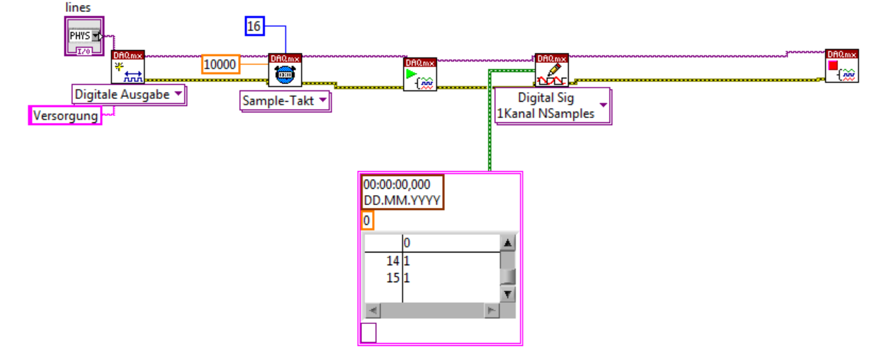
I can produce a digital output signal of some sampling rate 10 kHz with the acquisition of data-assist. Now I would like to implement the same functionality with normal DAQ - screw, as I have to synchronize serveral exits lateron. However, I failed get the normal screws so that they work as the DAQ assistant. The most important thing is out the arbitrary signal with 10 kHz.
Thank you.
Thank you very much. The idea of watching inside the acquisition of data-assist helped.
-
Noise daq signals sent through an RC circuit
Hello
I'm trying to source various signals of voltage AC / DC through a device that contains resistive and capacitive. I'm doing some testing on very simple circuits - a polarization of the square wave out of an Ao of a DAQ 6368 route through a 1mW resistor, then a current to voltage converter sends a voltage in the AI 6368 channel signal.
With just a resistance, everything works fine - accurate readings of voltage/current, low noise, etc. But when I put a capacitor in series with the resistance, I get intense noise across a very broad range of frequencies. A 10pF capacitor double the noise, and a 100pF capacitor multiplies by 10 x or 15 x. The circuit, I am interested in the measure will be about have capacitance 300pF, more an another 300pF of involved additional wiring.
I'm doing something obviously wrong, capacitance is inherently ruin amplifiers?
I feel like I should see nice exponential decay or splitters of a capacitor, no noise from wide band/HF. Take a look at the photos I have attached with the included fft - they are taken to a 0 V DC bias circuit, showing the current measure in units of microamperes (I posted a similar question a forum recently switch and have determined that the problem is not the switch, but parasitic capacitance in the switch).
Thank you!
EDIT: added some pictures of 10 Hz 100mV pulses of square waves, all online is the trace of current time. The resistance of 1Mohm one looks great - 100nA for 100mV makes great sense, low noise, etc. But with the capacitor 10pF, wise capacitive spikes, but whats up with the rise in noise?
Hi Lynn,
Thanks for all the advice - the noise was much higher in frequency, up to 10 kHz region. I finally found my noise problems caused by Earth or impedance mismatch between my PXI and my bipotentiostat loops, so I'm doing the experience entirely using components PXI.
Best,
GIM
-
Hello
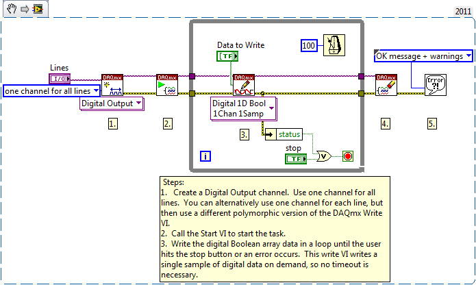
This should be very easy, but for some reason, I'm going to have questions. All I want to do has a switch control a digital output. I use a card NI 9742 Dsub (link), which should be capable of digital output.
My code, with a simulated map is attached. During the test I change the properties of the real card DAQ assistant.
Using this code, I can't get a DC output at all, my scope is all about 100mV. Using other cards, I have the analog i/o works fine, but for some reason, the digital output on this card isn't? In addition, if you look at the map, there are 8 green LEDs upward. I think that each specifies when an output should be enabled. When I turn on the switch, the corresponding led lights actually, but I can't measure a voltage? Is there a setting I'm missing?
I hope that makes sense. Thank you!
-secondary question: once it works, how can I change the output range. The specs say output 6V - 30V, but I do not see where to change that.
g e m e n i,
I looked at your code and noticed that it includes only a DAQ Assistant and a Boolean matrix of values to write.As it is currently, the VI will be only write a single value and then stop. In order to write constantly, you will need to place your code in a While loop.
If you see still no signal the evolution of 9742, consider opening one of the expedition DAQmx examples. You can find these examples in LabVIEW by going to help > find examples...
Try the following example: material input and output > DAQmx > digital generation > write hollow Chan.vi
-
How can I write a digital waveform to the digital output (traditional DAQ)
Hello
I use a NI 6023e, PCI, with 8 digital outputs. I generated a digital waveform. How can I write for a specific digital production line now?
I only have Labview 7, so I can't use DAQmx.
Thank you very much
-
NEITHER 6052e: can I re - route the analog output of DAQ for PFI?
Hello
Does anyone know if it is possible to route analog output to one of the PFI (e.g. PFI0)? I use NEITHER 6052e and I would do the following: 1) output a signal to DAQ0; 2) then a few hundred milliseconds a signal of DAQ1; and then 3) read out a simple analog pulse on any output connector external to trigger an external device.
Thank you very much for your help!
Hello sometimes.
Could you please provide more information about your hardware configuration:
What devices are DAQ0 and DAQ1?
Are you using a PXI and PCI 6052?
When you say AO reroute to PFI do you mean you're trying to wire AO into a PFI line for release purposes or are you trying to exit and the analog signal of a PFI line?
-
Question output noise reduction
Whenever I have apply the noise reduction in LR3 Beta 2, the settings will be displayed in the preview area in LR, but as soon as I export to JPEG, the treatment disappear. It only occurs with noise reduction - all other treatments remains on the image. Any help?
I understand the confusion. This is a gap in low resolution
displays that requires a lower resolution image must be
generated to show you a preview. Lightroom 3 tries to give you a
an extract which is quite accurate in using subpixel rendering, but
Lightroom 2 gives you an overview particularly badly to develop which is
a side effect of the way the preview is generated. He uses a much lower
resolution interpolated to the version of the image display resolution
for reasons of speed in the zoomed-out view. Often, this shows you
more noise is actually there because you don't get the average
of pixels you should get when zoom you back. Sometimes, however, as
in your case, it shows you actually less noise than is really there.
Both are objects of art of the choices made. Only when you zoom
1:1 will actually receive you a correct rendering of the image taking everything
the parameters of development into account.
-
We can connect the output of the sensor directly to the DAQ hardware or any interface necessary?
We can connect the output of the sensor directly to the DAQ hardware or any interface necessary? If so wat kinda necessary interface?
How to change the sensor output to match entry-level data acquisition?
If the sensor output beyond daq range is provided. What are its effects? pls answer
-It depends on your signal and the type of device you have. Your DAQ provides a package of signals? Also, what type of signal you want to measure? You must select DAQ that matches that. Take a look at the following before you start:
Getting started with NO-DAQmx: Main Page
And take a look at table 1 in the following article to wire your signal to the right:
Wiring and considerations of noise for analog signals
-You will need to use external circuitory to match the input of data acquisition range.
-You could damage the unit.
If you have any other questions, please after return. And, don't forget to give more details about your configuration, the hardware and what you're trying to do.
-
Output settings reset inside the DTS sound
So the C series + ugly + built in the Strait, we all know. No matter, like home, I run my sound through some nice speakers and on the road I use headphones. However, to get a good sound, I pass parameters DTS from inside to outside. And voila, sound quality.
However, DTS settings reset internally, forcing me to change it manually every time. Not the biggest problem in the world, I'm okay, but still annoying.
Anyone has an idea on how to change the default setting on the outside? See you soon!
If there is no definition of this option is enabled by default, so I guess you should choose external, output noise always using the DTS sound profile.
-
Poor quality with cDaq sinewave output
I have a cDaq 9174 with 9263 analog output module. As part of a larger system, I try to create a sinusoidal signal generator but have big problems getting something like a reasonable waveform.
I use the express VI the sinus sumulate, then in the service of analog output of DAQ assistant and just feed of amplitude and frequency values in the sine function.
Above about 50 Hz, everything works well, but 50 Hz 0.1 Hz (the range I need to use) the waveform is terrible, not sinusoidal and sometimes cut off upwards. Possible combinations tried as much as I can think of for settings of the sine and the analogue output function, without success. I contacted OR this topic and they executed my VI and say it works very well. but they do not have the same material as me to try it. I have two lots of material and the same problem occurs on both, so is not a defective hardware problem.
I use an external oscilloscope to measure the waveform and we tried two different units, with the same results on both.
-
9421 sinking digital input module toggles output
I have a digital input module 9421. I'm only using a single port (0). The line is 'high' all the time. I can see it on the lights and the tool MAX. I can turn on/off the line and see the LED and MAX change, so I know I have the cable correctly thing. But in normal operation, it is always powered.
It is, when I run LabVIEW mode trace with a probe on the output ExpressVI DAQ, I see that all the other times my code, the output of flicks from true to FALSE and vice versa... and so on. The acquisition of data ExpressVI is inside a while loop.
Any thoughts?
DH
I have chosen the cDAQ "simulated".

DH

Maybe you are looking for
-
I find friends on my Mac?
-
We try to update an ICC with stuff from 2015. He had been working fine on Labview 2014. It's a CPI for Siemens, which has a 1000th Intel NIC and also a map of network Intel 8254. Apparently, it starts up and tries to get an IP address from the DHCP s
-
How to implement the automatic calculation is Visual Studio (I'm new to VS)
IM new vb and I wondered how I would do automatic calculation in my application Here are my Apps UI (I wasn't expecting to get out that big) What I'm trying to do is 1. number of nights * $55 = Total cost night 2 total cost of night * 10% = load of E
-
C4795 all-in-One Printer installation
I would like to install my C4795 printer to another computer and I don't have the operating manual or the installation disc. Is there a way to do it with the disc or if I order a disk somewhere? Please keep in mind, I'm no computer in order to have
-
Smartphones blackBerry Contacts without Outlook management?
Hi all I have Office 2007, but unfortunately, it is not the version that includes Outlook. Are there 3rd party desktop applications that work with Mozilla Thunderbird, or as a stand-alone contact management? TIA, -Mike