Outputs with Om 50 digital TTL
Hello
Is all DAQ Multifunction (USB, PCI, and PCI - e cards formats) with digital output that operate on the entrance of Om 50? It can also be taken out of the meter.
Thank you
Vasilich,
Print digital only devices with an output impedance of 50 ohms are our HSDIO devices. If the reason you want a multifunction data acquisition is to use the DAQmx driver, then devices 6535/6/7 would be better because they use the DAQmx driver. That said if you don't go to high speed with your release you will be able to get away with using DAQ hardware with an output greater than 50 ohms impedance. If it is absolutely necessary that you use a device with an output impedance of 50 ohms HSDIO devices is the only option. I hope this helps.
Tags: NI Hardware
Similar Questions
-
Synchronization of analog and digital output with the external sample clock
Hello
First of all sorry for my English, I will try to explain what I want to do.
I want my PCIe-6321 to send two custom signals (modification sawtooths) on a mirror controller. I would also like to generate output with my card at the beginning of each tooth of saw. Everything must be synchronized with an external k-clock signal of 100 kHz. The idea is that whenever the PCI receives a trigger to external clock, it sends two analog output voltages and when he received 1024 clock ticks it will also send a pic of triggering TTL. What I do is first prepare the map and after that in a loop sending and modifing the output values of the two signals and at the same time send a digital signal Boolean in each arch, so when's done it 1024 iterations of the loop I send an event to the digital port. Attached you can see.
The problem is that I don't know how to synchronize both. Can I use the sample clock just to the analog output? I can use sample for the two outputs clock, or do I need to use the output of the meter? If don't know how to use it here.
If I do nothing else bad/wrong, I would be grateful for feedback.
Thanks in advance,
PabloI don't know how but I find the solution. I'm generating more than a positive value (as I was triggered maybe very fast the oscilloscope has been absent there). If I put the sample clock of digital output to use the sampling/ao/Dev1 clock that it doesn't, but if I put to use the same source as the OD (terminal where my external clock is connected), but the trigger to start the DO to be Dev1/ao/StartTrigger this works. I don't really know why, but it does.
Thank you for your patience and your help. I put here the final code.
-
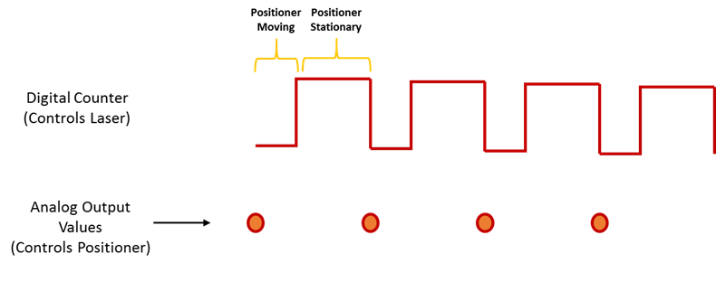
Analog output with counter Falling Edge
Hi all
Here's the iamge which describes what wishes to accomplish. I would like to trigger that the AO output with the edge of the fall of the meter.
I have set the clock for my AO as the counter.
The analogue output should be raised whenever the Digital signal meter falls
SAMPLE_SIZE = 80
SAMPLING_RATE = 40 #Samples are written every 25 milliseconds
TIME = float ((SAMPLE_SIZE) / (SAMPLING_RATE))CREATE TASKS
CREATE CHANNELS OF AO
CONFIGURE THE TIMING CHANNELS
DAQmxCfgSampClkTiming (taskHandleAO, "PFI12", SAMPLING_RATE, DAQmx_Val_Falling, DAQmx_Val_FiniteSamps, SAMPLE_SIZE)CREATE TASKS
CREATE A CHAIN COUNTER
# Time high-low + time equals 25 milliseconds and is proportional to the frequency of sampling
DAQmxCreateCOPulseChanTime(taskHandleD,"DAQ/ctr0","",DAQmx_Val_Seconds,DAQmx_Val_Low,0.00,0.005,0.020)# The values of voltage DAQmx writing
DAQmxWriteAnalogF64(taskHandleAO,SAMPLE_SIZE,0,10.0,DAQmx_Val_GroupByChannel,Voltage,None,None)# DAQmx AO task start
DAQmxStartTask (taskHandleAO)# Counter DAQmx Start task
DAQmxStartTask (taskHandleD)#TIME is equal to the total time for the writing samples
DAQmxWaitUntilTaskDone (taskHandleD, 2 * TIMES)I get an error every time that I run the task:
DAQError: Over Acquisition or generation has been stopped until the required number of samples were acquired or generated.

 function DAQmxStopTask
That's because my AO task is stopped for some reason any.
Is there an obvious problem with the code. Can it be structured differently?
best regards,
Ravi
I do all my programming in LabVIEW, so I'm pretty limited to help with programming syntax text. That being said, here's what I * think * I see:
Your AO task issues a call to DAQmxCfgSampClkTiming, but is not your task of counter. This probably leaves you with a meter spot which creates only a single impulse, which causes only a single AO D/A conversion. In LabVIEW when I need a pulse train, I would call a similar function of the synchronization with the clock mode is defined as 'implied '.
Hope this helps you get started, I don't know enough to give you the specific syntax in the text.
-Kevin P
-
I bought a book of game Google and downloaded the CMHA on my desk. When I try and open it with my Adobe Digital Edition, I get the error message "license make mistake. "License server communication problem: E_Stream_Error.
Response to SMcLeod8:
Hello, I managed to solve my problem of E_STREAM_ERROR regarding the Google Play ebook. The short answer is to use ADE 4.0.3.
When I met the problem of the E_STREAM_ERROR, it is with ADE 2.0.67532 on Windows 7 (and this had no problem handling the Kobo CMHA, OverDrive files, open a library and a sample epub BCAM from Adobe itself). This is why I would not upgrade my 2.0.67532 to the last 4.0.3. Instead, I used another Windows 7 PC and installed ADE 4.0.3. On my first try, I allowed the 4.0.3 without ID, and there was an error E-GOOGLE_DEVICE_LIMIT_REACHED. I then allowed with the Adobe-same ID * as my 2.0.67532 PC. It worked as I could get my epub from Google.
As I don't expect a response from Adobe technical support, I guess that now Google license servers do not work with Adobe 2.0.3. I hope this will help you solve your problem - at least to get your ebook in ADE first.
However, I would be careful replacing 4.0.3 of my 2.0.67532 I wouldn't be surprised if the latest version will not work with other suppliers of epub for social mobilization. For me the upgrade to the latest version of the software is never the best solution - it could solve a problem, but creates another.
Note: * I understand that you can authorize up to a total of six computers with the same Adobe ID. Not sure that this policy is still standing.
-
Hello
I have a table as below.
create the table members (member_id varchar2 (128), name varcahr2 (128))
Insert members (member_id, name)
Select '5591558906BA4A019FAB99EDAA26E62B', 'abc' from dual union all
Select '0F1E7A1B363111D3BDF20008C707ACC6', 'eur' from dual union all
Select '49C73ABC91404F8E825314FF6369E432', 'ure' from dual
I want an output with quotes
for example
If I have
Select member_id members
give me
5591558906BA4A019FAB99EDAA26E62B
0F1E7A1B363111D3BDF20008C707ACC6
49C73ABC91404F8E825314FF6369E432
instead I need output like this
'5591558906BA4A019FAB99EDAA26E62B '.
'0F1E7A1B363111D3BDF20008C707ACC6 '.
'49C73ABC91404F8E825314FF6369E432 '.
any help on this is much appreciated
Thank you>
I want an output with quotes
>
Then put quotes in your queryselect '''' || member_id || '''' from members -
Digital output with NOR-9401 in cDAQ-9174
Hello
I have a cDAQ-9174 with an e/s digital NOR-9401 module. Now I want to output Digital signals on line0:3
$line0: Boolean 1 time = 10ms
Line1: Boolean variable 1 time = 20ms
row2: Boolean variable 1 time = 30ms
line 3:20 pulses (period = 250us, duty ratio = 0.5) after a time = 40ms
the value of line0:3 must be Boolean 0 after 45ms
Can someone let me know what I need to work to solve this please?
Thank you all for your help.
Concerning
Bing
Thank you Christian for your quick replay.
I have some experience in programming of microcontroller with C. I learned LABVIEW for about 1 month and followed a lot of demons in line and tutorials. I know that nodes DAQmx Data Acquisition screws and fundamental property.
As I said at the beginning on the $line0, lin1and line2, they serve to control the relay in my circuit. 10ms could be controlled with the OS clock. Pulse of line3 series is used for IGBT gate signals, which is the critical moment. I want to use the clock machine to accurately control line 3 and synchronize at the same time the pulse with analog inputs from an another two NI9206 modules in the same cDAQ chassis.
I just want to know more on the digital line demand signal relay output and a correlation between the line of analog input-synchronized finished pulse output. Waveform diagram is locked.
Thank you.
Bing
-
Implementation of multiple digital outputs with a box USB-6009
Hi all
I write the code to implement a USB-6009 multiple digital channels, digital outputs independent. I have configured the function of "DAQmx create Channel" to create 'a channel for each line', but I can't understand how to access and control these channels separately. Pointers would be greatly appreciated.
Thank you!
I thought about it. Never mind.
-
Digital output with timer (Simulation)
Hello everyone, I just found out how LabVIEW program a week ago. I try to do a simulation of digital output by LabVIEW (my attachment). In this simulation, I have a slider as an input (0-10 V), two digital controls (upper limit and lower limit), a waveform graph draw these 3 evaluates and two Boolean LED (P0.0 and P0.1) as indicator. In this simulation, you can fill any number (between 0 and 10) in numerical order as a limit for your entry cursor. If the entrance of a cursor exceeds these upper and lower limit, then the Boolean LED lights, P0.0 so exceeds the upper limit, and if P0.1 exceeds the lower limit. The problem is that I do not know how the timer for those Boolean LED. As an example:
(1) make an entry of cursor,
(2) if entry (1) exceeds the upper limit, P0.0 lights for 5 seconds, then turn to during 10 second.
(3) if only 10 seconds, you change the entry back to normal (between high and low limit) then P0.0 will stay turn of until the cursor entry exceeds the upper limit again,.
(4) If, in this second 10 you has not changed the entry (the stay exceeds the upper limit) then P0.0 repeats the process (2) until you the entrance to cursor back to normal.
(Same process for entries exceed the lower limit).
Can you help me do this timer? Thank you

Concerning
Juventom
Hello
If you don t mind I would just give you some advise to your code. To determine the data stream you can also use only the error wire connected to the loop. So Don t you really need, it's beter not not to use variables. For your solution, you can use something similar to what I tried for the upper limit in your program. It is added as an image.
Hope it helps
-
Simultaneous analog inputs and one digital output (with NI6221M). Critical moment.
Hello!
Please excuse my bad English.
Idea:
I developed a device to measure the absorbance of light in the sample. The device will have 20 light emitting diodes (led) and 30 light sensitive photodiodes (DP). I have a PCI NI6221M card. As there are a lot of LEDS and PDs the device must use external multiplexing (MUX). The Assembly is shown in figure "DOAI System.JPG". "delta t" figure is not important. It may be zero, one or a few Americans. It is not essential for the operation of the device.
Opreation:
PD 1 will be multiplexed to the AI and the LEDs blinked (turned on and outside), one at a time. Then 2 PD will be multiplexed to the AI and again all LEDS flashing one at a time. The sequence continues with 3 PD, PD 4 and so on. Each blink a led should produce a sample of I. The sampling frequency of the AI should be about 12 kHz (so 80us for example).
Q: It will be possible to obtain from the Commission of NI6221M?
Problem:
I realize that there will be problems. When c generates an address on the MUXs there will be a delay until the LED driver, PD and input amplifier electronics of HAVE it settled. Q: Is it possible to delay the sample clock HAVE some 10 microseconds as to allow that to happen? (Perhaps use an internal counter operating on a basis of time much faster than 12 kHz sampling or use another for me still a feature is not known. May actually leave the sample clock HAVE be the 'master' and instead of delay clock.) Please see the "" calendar of GOT it. "" JPG ".
Q: Is it possible to control the time to settle for AI? That is to say that he can use the 6221, say, 30 US to settle before it reads the value. What these 30 arrive us before or after the flank of sample clock?All reviews are much appreciated,
Markus
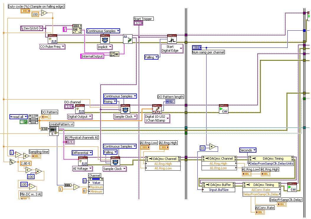
Hello!
Just thought I should fill this thread by posting the code that we use now. The moment is as before, but we've added a few nodes property to coacha few parameters. In addition, 6221 has been replaced by a 6259Usb device that allows us to have the best insulation galvanic and more synchronized digital I/o lines.
-
Triggers the analogue output with PCI-4461
Hello
I'm trying to generate a signal of analog output triggered with a card PCI-4461. First I tried to use the feature OR DAQmx 'start analog edge' with the way analog input AI0 as the source and the channel analog output AO0 as task. After it gave an error that I tried to use the NI DAQmx 'start digital dashboard' function with PCI0 as source and channel of analog output AO0 as task. It ran, but did not produce any output. Now I wonder if I can use the trigger analog or digital of the PCI-4461 to all of the output.
Thanks for support you,
Pribislav
Pribislav salvation,
you still have this problem? I did exactly the same configuration (power play) and it works fine on my system. The PCI-4461 does not support analog triggering, that's why this error occurs.
Kind regards
Michaud
-
Synchronization of the inputs and outputs with different sampling frequencies
I'm relatively new to LabView. I have a NOR-myDAQ, and I am trying to accomplish the following:
Square wave output 10 kHz, duty cycle 50%.
Input sampling frequency of 200 kHz, synchronized with the output that I get 20 analog input samples by square wave, and I know what samples align with the high and low output of my square wave.
So far, I used a counter to create the square wave of 10 kHz, display on a digital output line. I tried to pull the document according to (http://www.ni.com/white-paper/4322/en), but I'm not sure how sample at a different rate than my clock pulse. It seems that this example is intended rather to taste one entry by analog clock pulse. There may be a way to create a faster clock (200 kHz) in the software and use that to synchronize the analog input collection as well as a slower 10 kHz output generation square wave?
I eventually have to use the analog inputs to obtain data and an analog output to write the data channel, so I need the impetus of the square wave at the exit on a digital PIN.
How could anyone do this in LabView?
Hi Eric,.
All subsystems (, AO, CTR) derive from the STC3 clocks so they don't drift, but in order to align your sample clock HAVE with pulse train that you generate on the counter, you'll want to trigger a task out of the other. I would like to start by a few examples taken from the example Finder > Input and Output material > DAQmx. You can trigger GOT off the train of impulses, start by Gen digital Pulse Train-keep -you probably already use a VI like this to generate 10 k pulse train. AI, start with an example like Acq Cont & chart voltage-Ext Clk - Dig Start.vi-you'll want to use the internal clock so just remove the control of the "Source of the clock" and it uses the internal clock. From there, simply set the "Source of the command" either be the PFI line generates the meter, or ' /
/Ctr0InternalOutput '-assuming that you are using the counter 0. You'll want to make sure that the start of the task HAVE faced the task of counter I is ready to trigger off the first impulse. They should be aligned at this point. For debugging, you can use DAQmx export Signal to export the sample clock - you can then brought the train line and the PFI pulse to make sure that they are aligned.
Hope this helps,
Andrew S
-
Frequency of maximum output with USB-6008
I have a digital circuit containing 3 exits, 3 inputs digital and analog 1 entry in labview with my USB-6008. When I connect to the entrance (via the DAQ assistant) analog, the output frequency is reduced to a maximum of 27 Hz, but I need 50 Hz. is possible to do?
Ah. You'll need a DAQ better than the 6008, to do.
There is no train generation feature buffering or the pulse on the 6008. The outputs are all timed by the software, you cannot build a table and tell the 6008 in the output array. Out of the 6211 must be able to produce this signal. Series X-series Renault will do what it takes; the USB-6341 is probably your best option.
-
I use the outgoing/incoming analog DDK with the DAQ 6341 SMU map.
The examples, for example aoex5, show a single timer (method outTimerHelper::loadUI), but the example shows the DMA loaded with same size of vector data.
There is a comment in the outTimerHelper:
 call rogramUpdateCount, which implies that memory sizes different pad per channel can be used.
(the comment is: switching between the sizes of the various buffers is not used)
Nobody knows what should be the format the DMA buffer for data from multiple channels with different frequencies?
For example, we want a0 with a sinusoid at 1 kHz and a1 with a sine wave of 1.5 Khz. What looks like the DMA buffer?
With the same frequency for each channel, the data are interleaved, for example (ao0 #0, ao1 #0; ao0 ao1 #1, #1,...), but when the frequencies for each channel is different, what the stamp looks like?
Hello Kenstern,
Data are always intertwined since each card has only a single timing for each subsystem engine.
To AO, you must specify the number of samples that will be released to the AO. You also specify the number of channels. Because he didn't is that a single engine timing for AO, each AO will be channel will be updated at the same time to update clock tick. Data will be interlaced exactly as shown in the example because each channel AO needs output at each tick of the clock to update. The data itself can change depending on the frequency you want to copy.
kenstern wrote:
For example, we want a0 with a sinusoid at 1 kHz and a1 with a sine wave of 1.5 Khz. What looks like the DMA buffer?
With the same frequency for each channel, the data are interleaved, for example (ao0 #0, ao1 #0; ao0 ao1 #1, #1,...), but when the frequencies for each channel is different, what the stamp looks like?
In your example, you must come with an update rate that works for the two waveforms (sine waves of 1 and 1.5 KHz). To get a good representation of a sine wave, you need to update more than 10 x faster than your fastest frequency... I would recommend x 100 if possible.
Update frequency: 150 KHz
Channels: 2
Then create you stamps that include complete cycles of each wave you want to produce based on the frequency of update. These buffers must also be of the same size.
Buffer 1: Contains data for the sine wave of 1 KHz, 300 points 2 cycles of sine wave
Buffer 2: Contains data for the sine wave of 1.5 KHz, 300 points, 3 cycles of sine wave
You can Interleave them as before. When the data are performed through the ADC, they are out different sine waves, even if the AO channels are updated at the same speed.
-
Python DAQmx triggers a reaction of output with an input signal
Hello world
I use a NOR-6251 Board with a python GUI.
I want to send data on the output channel on each falling edge of the input signal when I click on a start button.
The level of the output signal may be 5v/0/1 (0v).
The frequency of input signal squares is 2 MHz for 50 on it (see the attachment for more information).
I don't know if it is better to use the analog inputs or input meter for the input signal. I think I have to set a clock pulse at the frequency of 10 MHz.
I tried several solutions with bad results.
Does anyone have the answers to my problem?
Thanks in advance.
Thanks for your reply.
It works...
-
Is it possible to output a string and digital front without the border around it?
I know that I can change the border around a string or a digital output to the screen using modern or classic, but is possible to output and the numeric values to the front channels without the border around it? This is particularly useful for panels to front I want to print.
Thank you
Chuck
You are to halfway it using the conventional versions. The next step is to get out of your paint tool and paint the color of the transparent border.
Ben
Maybe you are looking for
-
My HP G6 1250SD screen is broken. Now, this isn't a problem, I want to continue to use the laptop with an external display. The laptop has not automatically recognized the screen. How doe I resolve this problem? I already tried another screen and you
-
Z Turbo Drive 512GB (G3G89AT): support low-profile for Z Turbo Drive 512 GB in Z230 SFF Workstation
Does anyone know how to get support low-profile needed to install a Turbo Z Drive 512 GB in a Z230 SFF workstation? I realized this quick Spec HP card for my desktop which is located at the following link: http://WWW8.HP.com/h20195/v2/GetDocument.asp
-
my wireless router appears to be defective
my century link internet service is not stay, even if I unplugged the modem for 15 minutes and much more. the lights indicate the wifi works, but I can't remember the internet service. I'm not technological, so I need a simple language. Thank you.
-
If remove old windows that delete my pictures, music,
If I delete windows old will that delete my pictures, music, Favorites, bookmarks, my fav.music on utube pdf speed ect.
-
Pavilion DV7-6c23cl AMD quad core laptop there a 2nd Bay and a port?
Hello I'm looking for a laptop that can accommodate two hard disks (I want a smallish SSD for the system and a conventional SATA, more great for data), I've read that at least some of the Pavilion DV7 laptops with a drive Bay 2nd (& port). Costco is