PCI-6601
Looking for example c code to write a single pulse of the outer edge mounted trigger with the 6610.
You want to be able to control the pulse width, no delay.
Thank you.
Hi Doug ^ 2.
There are a lot of great examples on your computer with your software of NOR. If you go to your Windows Start Menu > all programs > National Instruments > NOR-DAQ > text supported the Code > ANSI-C examples. From here, it looks like you want to go to the counter > digital pulses and find your appropriate example.
Good luck!
Tags: NI Hardware
Similar Questions
-
Calendar synchronized with Diuble pulse using PCI-6601
Hello
I'm trying to run a PIV of Labview 8.5.1 system using a PCI-6601 map at the exit of the signals for the laser and the camera.
This requires a line for the camera, one for the FPS (first removal of pulse) and one for the Q-switch.
The difficulty is in the need of a double pulse on the Q-switch for mode double frame PIV.
The distribution box that I use is not one NOR one and I don't have access to 3 outputs four against, otherwise, quite simply, I would use a BNC t with two pulses slightly staggered junction.
I have access to a BNC-2110 timing box, but I think it is not compatible with the PCI-6601 and have no funds to buy a BNC-2121 right now.
I managed to create a double pulse by using one of the counters with a finite number of impulses set to 2 and then stop the task, then run this in a timed loop.
However, it is then based on the software, which is not precise enough for the application, and I can't figure out how to get the timed loop to run from the time of 20 MHz of 6601 map base.
I could be missing something obvious here, or perhaps is more annoying? I'm fairly new to DAQmx.
Thanks in advance
Joe
Dominic makes a good point about the operating system, but really the best solution is to use the hardware timing when possible.
I have set up an example that shows how you can implement different sets of impulses finished using the calendar of the Commission. It requires the use of two meters, but then again a generation of impulses finished the fact (on the 6601).
Communities: Generate several Cycles pulse finished using two countersAlternatively, if you have another signal that you want to use to trigger each set of pulses (rather than to specify a rate so that they occur as in the example above), counters on a 6601 are redeclenchables then you can use the external signal to trigger the generation over time and time again without having to stop the task in the software.
Best regards
John
-
What are the options for 3 bit for Hw_Arm_Sel in PCI-6601 field
Hello
I'm programming our own driver to operate the PCI-6601. For our application, we need option arms material. I know, it is possible to use 2 counters for this, but NEITHER-TIO also supports hw_arm. Although it is not explained in the registration document at all, after some tedious verification in the DDK examples I found that the pieces are in the Gi register metering mode. I know that the position of the HW_enable as well as the position of the 3 options sellect bits PIN. What I don't know is what are the options of 3 bits for Hw_Arm_Sel field. I contacted the support NEITHER, but received no support. How can NEITHER sell boards and when a customer who doesn't use LAbview or Measurement Studio, or DDK, but implements its own driver is then so arrogant at least of NOR? Also, how can OR publish only a part of the records of the Board of support and when a customer contacts and request for some records do not get supported at all? I can't predict the missing records, and he is professional enough to document comes in part from records of 660 x Instruments. And, upon request, you have nothing.
I hope that someone from the community are aware of this Hw_Arm_Sel 3 pin option. Otherwise, there is just one option of the error and the trial. Or simply throw away the jury.
Dr. Kirco Arsov
Hey, sory for the delay in my response. It works and it works very well with the description of Joe and Joe, thanks for your great help. I greatly appreciate. Now we finally also have this option as we wanted it and it works fine.
-
Control correctly 3 heartbeats at 3 meters of material using PCI-6601
Hello
It is a sequel to a previous post
http://forums.NI.com/NI/board/message?board.ID=40&message.ID=7914#M7914
as for control a PIV of LabVIEW rig using a PCI-6601.
The task requires the production of pulses in three outings of the counter. The Q-switch laser, to a double pulse (which is resolved in the previous post), while the other two are simple impulses. It is important to be able to control with precision the difference in width and pulse between pulses.
As far as I understand, I need to configure timers to start and then run from the material without other software entry
I tried using the "initial deadline" option when creating counter channels, but it is very innaccurate (probably that uses the software?). Similarly, using the lag in call loops option does not produce a time delay (and requires the use of a meter as a synchronization source, leaving me without enough counters)
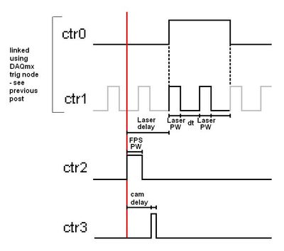
Below is a basic diagram time for a single iteration, keeping in mind that this must be repeated in the range of 100-1000 Hz, approximate pulse width (PW) would be 2 microseconds and delays in the region of 500 microseconds.
I need to be able to define
delay of Cam and laser delay with precision (and the pulse widths must be easy in theory)
Sorry if I forgot something important and thanks for your help
Kind regards
Joe
Hi again Joe,
We could just trigger all out 2 meter (pulse FPS which seems to start the acquisition as a whole).
CTR 2 would be a continuous pulse generation (at the rate we want to re - triggered the entire process).
CTR 3 would be a unique generation of impulses of retriggeralbe, with an initial delay.
CTR 0 and 1 are a bit difficult in the context of the rest of the application.
I think that the suggestion I posted in the previous thread should work fine by CTR 0 triggered with an initial delay.
Otherwise, we could do an output meter redeclenchables finished, but if I remember correctly there are specific behaviour with the initial delay of the finished products redeclenchables counter that could give us unexpected results (I would find the link but ni.com seems to be down at the moment).
I won't be back in the office until next week so I don't have any material to try this, but I think that should help you get started in the right direction at the moment. The desired behavior should be achievable, but it might take a programming smart everything for line lift correctly.
Using a trigger external or not should not affect the programming of the double line impulse which is the most difficult aspect of the application.
-John
-
PCI 6601 - Info from the digital output
Hello
I have a few questions about the PCI-6601.
Are the open collector?
I need to provide an external 5V traction to DO?
Thanks in advance for any help
,Marco
In fact, I did... but probably without enough attention...
Therefore: Yes I need to shoot to the top of the PFI externally.
-
Support for Windows XP x 64 for NiDAQmx PCI-6601?
We use the PCI-6601 with Windows XP x 86 and we want to move to Windows XP x 64.
I have notced the discussion on this forum:
http://forums.NI.com/NI/board/message?board.ID=250&requireLogin=false&thread.ID=20698
Are there updates on support for XP x 64? The latest version of the software only supports Vista x 64 so far, and we are unable to use it for our application.
Thank you.
Erik
Hello Erik,.
Please use the support NEITHER. From now on, we still have no support for Windows XP x 64, and due to the massive amount of Windows users from XP to Vista and beyond it is doubtful that we will in the future have the support for XP x 64. From now on, your best bet is to stick with your current operating system, or if you need to move to 64-bit then, as you have already mentioned, we manage Vista x 64. I hope this helps.
Kind regards
-
PCI-6601 reading pulse without stop the meter
Hi, the problem seems to be simple, just for the moment that I did not came up with a reasonable solution. I'm programming the meter 6601 for the following using my own routines of driver (in visual studio 2008 C++) for read/write registers. I follow carefully the DDK examples. I started with the example 1 and 4, and it works very well and now I have to somehow come up with the following code:
1. I use the signal specific to 10 MHZ external H. MAser as input to the meter.
2. I start the meter with arm software and am constantly read the values of the counter.
3. I want everything just to read a single pulse (1PPS) and make the absolute time of the counter in time synchronization UTC. He should simply give me the meter reading of the rising edge of the PPS signal but after that it should be possible to read the counter as usual by reading the save save values, so read pps without stopping, nor anything in the registers of meter loading or b, simply give a pulse reading and continue even as 2...
Any suggestions?
Hello
problem solved, but anyway, to all those who might have a similar task, here are the raw extract of what I've done (code names and function are similar to the DDK, but has nothing to do with the DDK)
Sub yourclass::yourppscountfunction()
{m_stopPPS = false;
first reset internal values
card1. Write_G01_Joint_Reset_Register_G0Reset(); reset the counter 0
card1. G0_Reset_Registers_Values (); Reset internal values
Disarm
card1. Write_G0_Command_Register_Disarm (true);
load the initial value of 0
card1. Write_G0_Load_A_Register (0x00000000); counter should start with 0
card1. Write_G0_Command_Register_G0_Load (); tells to load the initial counter of a register value
Set the source to time external base
card1. Write_G0_Input_SelectRegister_SourceSellect (1);
Select the axis dedicated to door sellect (default value in this case, PFI_38)
card1. Write_G0_Input_SelectRegister_GateSellect (1);
card1. Write_G0_Mode_Register_Gating_Mode (2); rising edge Gate
card1. WriteIO_Config_Reg_Pin36_Select_out(); Configure the PFI_36 PIN to drive the output
card1. Write_G0_Mode_Register_Output_Mode (1); We're out the TC, connect to a counter2 to count the animated buttons
Configure the PFI_36 PIN to drive the output (not made here)
card1. Write_G0_Mode_Register_Trigger_Mode_For_Edge_Gate (3); Gate not used to start or stop
card1. Write_G1_Command_Register_Synchronized_Gate (true);
card1. Write_G0_Command_Register_Up_Down (1); counting direction up
card1. Write_G0_DMA_Config_Register_DMA_Enable (true);
card1. Write_G0_DMA_Config_Register_DMA_Int_Enable (true);
arm the meter
card1. Write_G0_Command_Register_Disarm (false);
card1. Write_G0_Command_Register_Arm (true);
WRITE THE COUNTER VALUES
card1. G0_Write_Mode_Registers();
card1. G0_Write_G0_Input_Sellect_Registers();
card1. G0_Write_G0_DMA_Config_Registers();
card1. G0_Write_Command_Registers();
while(!m_stopPPS)
{
PeekAndPump();
now loop to see if measures available PPS, if yes, read them and display
If (card1. Read_DMA_Status_Register_G0_DRQ_Status()) //if that something saved
{
unsigned long int counterValue1.
int HWSaveorSWSave;
HWSaveorSWSave = card1. Read_DMA_Status_Register_G0_DMA_Readbank();
if(HWSaveorSWSave==1)
{
counterValue1 = card1. Read_Save_Register();
m_editPPSreading = counterValue1 * 1.E-7;
}
on the other
{
counterValue1 = card1. Read_HW_Save_Register();
m_editPPSreading = counterValue1 * 1.E-7;
}This-> UpdateData (FALSE);
} //if something red} //while
card1. Write_G0_Mode_Register_Gating_Mode (0); gating disabled
card1. Write_G0_DMA_Config_Register_DMA_Enable (false); Disable dma
card1. Write_G0_DMA_Config_Register_DMA_Int_Enable (false); Disable interrupts
card1. G0_Write_G0_DMA_Config_Registers();
card1. G0_Write_Mode_Registers();} //after you might normally read the meter (PPS values are added to playback as UTC offset-> not done here)
to stop playback PPS and continue as normal counter where the values are simply red of the SW save registers
Sub yourclass::yourstopppscount()
{
m_stopPPS = true;
} -
"Data was overwritten before it can be read by the system" count with PCI 6601 with 20 MHz clock
Hello Aditi
What exactly is the purpose of the use of the clock of 20 MHz? You count the edges of it?
You can try to use the VI DAQmx Configure entry 'buffer' to increase the size of your buffer. You can also use the DAQmx channel node to set the DMA data transfer mechanism. If you create a channel node, you can get to this specific property through this path: counter of entry: general properties: learn more: Advanced
 ata transfer and memoryata transfer good mechanism.
 -
Digital filter on the sample clock 6601/6250
Hello
I use a PCI-6601 (Dev1) and the card PCI-6250 (Dev2) connected via a cable RTSI.
I apply a PWM signal to the 6601 ctr0 (Dev1 / / PFI38) and activate the digital filtering (100 ns) on the respective task (measure of the period).
I apply an analogue signal to AI0 map of 6250. As I am interested in a sample of analog measurement when the PWM signal changes from low to high, I put the clock sample of the AI task source ' Dev1 / / PFI38 "and the side assets of clock sample"Insurrection. "
Everything works fine, but I have a question:
The sample for the AI clock is the task the filtered PWM signal or not filtered PWM signal?
Kind regards
Udo
Hi Udo,
Great question! Digital filters are actually not part of the subsystem of counter, but rather the line itself PFI. So, if you have activated the digital filter for a specific line of the PFI, the signal that you route to any subsystem of the PFI line will have already crossed the filter.
It's actually the workaround to the PFI filters on M-series / TIO DAQ devices when you are not using meter (materials of filtering on each PFI line but the DAQmx driver allows only the filtering part of duties of counter on these devices).
I also wanted to emphasize that the 6250 itself has 2 onboard counters, then you could do the same thing using just the 6250 (unless you use more than 2 meters). I hope this helps!
Best regards
John
-
Helps the acquisition of photon counter data using LabView 12
Hey all,.
Student graduate Chemistry here new to LabView and are looking for some help moving in the right direction. I'm looking for help with connecting my meter to 12 LabView for data acquisition of trace-fluorescence photon PerkinElmer SPCM-AQR-14 (now owned by Excelitas Technologies). I just want to be able to acquire number of photon counts vs. time. Currently, I installed a PCI-6601 and use a BNC-2121 to connect the BNC of the sensor output. The detector has a pulse output digital TTL with 30 ns pulse width, and by contacting technical support on this issue, I was told that this pulse width was too short to always detected by the 6601, but can still go ahead and give it a try. Basically, if everyone is familiar with how to start with this configuration, ANY help would be greatly appreciated. As I said I'm all new to LabView and am currently spend all my spare time reading manuals and help files.
Please let me know if you need any kind of information to make me understand what I'm doing.
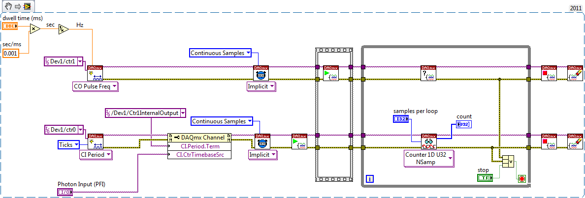
I would say something like this:
A measurement period the registry account out of the entrance of the samples as well as gives the meter. You will basically measure the 'period' of your sample clock fixed regarding ticks of the external photon signal.
According to the downtime, you may need to re-read several samples per loop so that the software can keep up with the incoming data. Also, the first sample is not useful because it represents the County between the software from the task of entry of the meter and the first clock signal - you should disregard/erase the first sample (or if you want you can set up a trigger to begin arms).
To do the same thing by using an edge County task would require using both the sample clock AND a counter reset signal - this not is not supported on 6601/6602 (even if it would be possible to set it up that way on a device of STC - 3 as a series of X).
Best regards
-
Hello
I use the generate an example of digital pulses finished vi to the ttl to generate from my card NI PCI-6601 impulses. I want to see the pulse output on an oscilloscope, how can I do this?
How can I connect a graphical indicator to show the pulse?
I have attached the vi that I use:
Missed the fact that it was only one meter.

You can always use a scope to connect to the output of the counter.

-
How can I more easily generate a pulse of digital output of finite length?
Hello
I need to open and close the two pneumatic valves using a TTL output (without load current or the output power) using a PCI-6280 or PCI-6601. The valves must open almost simultaneously and closing after different amounts of time elapsed (millisecond level timing, maybe 100 microseconds-level timing at worst). My current plan is as follows:
-Create a task with two digital outputs (type of waveform) and another task with a counter that generates a frequency set by the user (I know I can use the generator frequencies on one of these cards, but I would have preferred a counter - the best selection of frequencies).
-Wire the output of the counter at the entrance to clock two digital outputs.
-Output of the meter is digitally triggered by another digital channel which I use to control if the pulse goes out. Through its counter node, it is programmed to be redeclenchables.
-Two digital waveforms are drafted who have both consist of unique active high pulse (i.e. signals go ' down (for the amount of time user-defined) - low ".")
-These signals is written to their respective ports and their tasks have started, as is the task of the meter.
-Whenever the user wants to open taps, digital triggering is sent up and then back to low (this can be done with synchronization software, because it is not exactly when the fire valves). Whenever the user wants the valves open for a different period, different digital waveforms are generated and written in the buffers of the digital output channels.
My problem is that it looks like a lot of effort for me to go and I wonder if there is a much simpler solution, that I don't know everything. You can program a computer to produce a pulse of finite length? Is there a faster way to program a digital output for that channel?
Thanks to anyone who responds to their help.
It is certainly instructive. Thank you.
The thing is, I have only six total counters to work with and I have a lot of time to do things. To use these solutions, I would need to use 4 or 6 account counters required to my needs.also that I would need to synchronize their departures.
Overall, I stick to my method for now - less system resources and synchronization can be don by using the same meter of finished output clock and not to use a trigger to all.
Once again, thank you for your help so far.
-
Set up connection VI start and stop without losing or deleting data
Hello
I currently use a PCI-6280 M-series and a card PCI-6601 of counter measurements on Labview 2010.
I have 3 tasks implemented, 2 tasks of linear encoder on the 6601 counter and 1 analog input task with 4 inputs x on my 6280. All of these are timed with a counter on the 6601 through a RTSI line.
All of these tasks, I have a similar setup as the picture in http://zone.ni.com/devzone/cda/tut/p/id/9574 except that they are all set up as only "Log" and "create/replace" for the logging.vi configuration file.
Because I want to have the encoders permanently locate my position, I never "stop" the tasks of meter. However, I need to use the data acquired after each trip along the way to get and process location and subsequent analogue input data points I have. What I did, I would be 'stop.vi' my clock on the counter sample, and then open the PDM file, read the file PDM, get the table from there, close the PDM file, then "run.vi" the clock on the counter sample. However, I found when I stop the sample clock, not ALL data points have been listened to in the file.
For example, say I move my cart to 100mm to the right during recording, then stop the sample clock, get the PDM file table, find the size of this table called 'X' for future use. Then I get the ramasseherbe on the origin WITHOUT restarting the clock. THEN I start the sample clock and move from 100mm to the left. After that, I once again, stop the sample clock and get data from my file tdms starting at the offset of reading on "X + 1". I EXPECT that this table SHOULD start at 0 then go to the 100 mm to the left. However, what it does, is that I see the data begin at 100mm from the right for a few data points, then GOES to 0, then moves to the left as planned.
I propose this means that when I stop the sample clock, data from meters (stamp?) not all were listened to the tdms file yet, and when I start the clock, the rest becomes she dumped. Here, I'm confused because I thought that 'configure logging.vi' stream directly in the file without a buffer.
I was wondering if I'm doing something wrong, wait bad things, and if there is a way to apply what I want. As in, is there a way to dump data remaning in the "buffer" (I tried the tdms vi flower, but that didn't work and I didn't think it was relevant) after I stop the clock or something like that, or is my implementation to offshore competely.
Thanks for reading,
Lester
PS. have a way to read the most recent point counters would be great also. However, whenever I put the offset or relative to the most recent, it is said that I can't do during indexing, even if I saw a community post saying that it works with analog inputs. This is perhaps off topic, but yes, now I'm just trying to get the tables of PDM works, thank YOU!
-
mDNS 65549 answering machine Service error
I've had a problem for several months now with my devices not appearing is not in NOR-MAX. After studying the problem, I found that the ' charger OR ' assistance is not put on because the mDNS Responder Service Gets a 65549 error when Windows starts. Manually, I can start the service and get all to work until I restart the computer and the mDNS service gets the error again once. This has happened on several different computers with several different cards of NOR.
I tried to limit the problem by loading a new installation of Windows 7 32-bit on a new computer with the latest version of the driver NOR-DAQmx (version 9.5) and an NI PCI-6601 map. No other software is installed and no Windows Update is installed another Windows Service Pack 1 which is included on my Windows 7 installation disc. I found that the mDNS responder service starts automatically if my network cable is disconnected when Windows starts. If the network cable is connected to the start, the service starts only occasionally without the error.
I searched for information on the error 65549 and have found a few things to try, but nothing has worked so far. What is the mDNS responder error 65549?
Hi chvogt,
Would you be interested in trying a beta version of mDNS responder to see if that solves your error? If so, please send me a private message, thanks!
-
Hey Gang,
I have developed a driver for the client using a PCI-6601 and DAQmx embedded application. Now that we are in the deployment phase, the customer is shocked by the size of the NOT-MAX. (a rudimentary facility is about 1.5 GB) The only part of MAX that we use is to establish a connection between the PCI PnP and DAQmx resource name.
Has anyone written a utility to PnP without MAX branch?
Thanks for all the ideas,
Roger
Setup for DAQmx is a little big, but really not all that will be installed on the target system. However, I know a problem if you try to spread using a CD. Alternatively, you can ask end users to download on our Web site (www.ni.com.drivers), or you can host it on an internal network if your end-users are internal.
I just ran the installer DAQmx (including MAX) with all selected and checked the cost of disk. It was a little less than 500 MB. Remove everything except kernel driver, MAX and the support of the API (I chose the support of Visual C++ without examples or integration) and it came out to 300 MB. Use the disc button in the installer to see what will be your condition.
Maybe you are looking for
-
variables of user-defined data transfer
Hello I use the etherCAT 9144 chassis and is only supported by this hardware FIFO range target. After a search, I realized that the only way to transfer data from FPGA to the host by using user-defined variables. But these variables do not support th
-
Hello One thing bothers me and I would like clarification. During the "run Labview transforms its graphic code vhdl then vhdl en Bitstream . LabVIEW being synthesized, can get it back the vhdl code and the compiler on another software like model sim,
-
Help! I'm not a "geek" but a 63 year old grandmother who LIKES its Sansa MP3! BUT I only use it to listen to audio books. If I load into memory for audio book I can't 'play all' that let me play with in the dark in his bed for the next CD, or have to
-
Guest network never requires password
I set up and provided the password, but when you connect, it never prompt the password. It is completely open, when it is activated. Very weird.
-
I'm new to the community and I do not know if this the right place to ask my question, but here goes. I recently bought a dell inspiron 530 with pre-installed mcafee. I get a message that says that my computer is not fully protected. It is said that