FPGAS-vhdl
Hello
One thing bothers me and I would like clarification.
During the "run Labview transforms its graphic code vhdl then vhdl en Bitstream .
LabVIEW being synthesized, can get it back the vhdl code and the compiler on another software like model sim, simplorer... etc.
If so, I think that is not forced d ' use a card nor pour Configurator FPGA.
Thank you for being explicit, so that others can be answers

Hello
The LabVIEW FPGA compilation scheme is owner and therefore closed.
In other words, there is no way to recover the intermediate VHDL files.
This is illegal, and ownership of OR
Nice day
Well cordially
Tags: NI Software
Similar Questions
-
Using of FPGA VHDL IP and analog output
I use a system with Labview 2014 PXI. I've got Labview FPGA to program and run the card PXI-7854R.
I have the VHDL Code I want to use to control an analog output of the card. I use the IP integration node for this now but I also tried it making the process CLIP and still have not been successful. The problem that arises is that the IP integration node must be in a timed loop, while the analog output indicates that it cannot be put in a timed loop. Is there a way to provide an output of VHDL analog outputs of the card?
I tried to embed a loop timed within a while loop, but it still does not work.
I can't download the VI due to the policy of the company, but suppose I'm generating a sine wave in my VHDL code which must lead to the analog output of the card (the actual wave is company owner information but it is generated by a glance to the top of the table as a sine wave VHDL would be).
In an attempt to work the problem I retried import CLIP of the HDL code in a new project in Labview and VI. I'm still not sure about why it did not work with each other when I tried it.
For anyone who seeks to solve this problem:
I basically used this tutorial for the process CLIP: http://www.ni.com/tutorial/7444/en/
It also explains the differences between the CLAMP and the IP integration node.
-
Hello
When compiling a fairly basic FPGA VI, I get the following error:
61332 error occurred in niFpgaCompileWorker_ProcessStatusPipe.vi:1<><>
Possible reasons:
LabVIEW FPGA: An unexpected error occurred with the build tools. You try to compile the FPGA VI again could solve the problem.
The length of a line in "NiFpgaAG_0000002e_WhileLoop.vhd" is too long for xilinx 10.1. Length: 32845 Max length: 4150
Departure time: 17:22:06
End time: 17:22:12
Total time: 00:00:06Apparently, the vhdl code generator OR forgot to add some CR + LF in the intermediate files. How to work around this bug?
Kind regards
Lukas
Hi Lukas.
When LabVIEW compiles a VI, the VI is converted into virtual hard disk to be compiled into a file bit by Xilinx. As you have already understood, this error indicates that a line of code vhd had a length of 32 845 characters, which exceeds the maximum length of 4150 characters for the Xilinx 10.1.
Although 32 845 characters is very long, it is possible that this is due to the codification of LabVIEW rather than a bug. Some common causes of this problem include large enums, a matrix, or clusters in the code. Please check in your code. If you have no luck, please attach a screenshot of the code. I hope this helps!
Kind regards
Dayna P.
Technical sales engineer
National Instruments
-
decriptare codice vhdl generato da labview FPGA
Salve,
Quello che sto cercando di rates e di open a file vhd generato da labview FPGA during the United Nations VI, per vedere come viene scritto codice di compilaizione of it. Questo pole mi'd of poterlo confrontare con UN identico codice scritto directly in vhdl...
Salve,
non e possibile access al codice vhdl generato da LabVIEW FPGA compile durante.
LabVIEW e stato been proprio per evitare di codice vhdl texts scrittura/analysis.
-
Integration of IP node: VHDL + LAVIEW FPGA
Dear members
can I use a library set by the user or a parcel inside the IP integration node?
for example library that contain a function for fixed operations in comma?
As
Library IEEE;
Use IEEE. STD_LOGIC_1164.ALL;Use mustafa... pkg
Unfortunately, there is no way to directly access a block of memory of LabVIEW FPGA and an IPIN node. You will need to file a read/write memory next to your IPIN node node and manage lines of coordinates and data of your IPIN node as ports.
-
Hello
I have to import the VHDL code in Labview. I would like to know what the best solution what CLIP, integration IP node or node on HDL from the previous version of Labview if it is possible to use it.
Thank you
Hello
I think that these documents will help you to choose from, depending on your needs:
Difference between nodes CLIP and HDL
CLIP and the differences of node IP integration
Kind regards
-
Digital electronics FPGA Board Hardware Driver for Windows 10
My son just made me aware that his school has a dozen of National Instruments Digital Electronics FPGA boards, but they have never been able to get them to work or actually use them in the curriculum. It seems that he has left his instructor know that I worked with FPGA Xilinx for more than 10 years and now everyone counting on me to get these maps work. The issue seems to be the USB driver. According to the manual, I tried DEFB2012_5_2.exe which simply refused to run on this machine Win 10 x 64. DEFB_4_3.exe ran, but complained that LabView components have not been installed and that it would not continue. Could someone tell me please how to install USB driver ONLY so that we can download files of bits with IMPACT? In terms of a school budget, the investment they have in these maps is not negligible. Thank you.
Hello Dave and TGregor,
I hope I can clear some things here. I'm sorry that you run in so many questions with your boards OF FPGA.
First of all, direct responses:
The LabVIEW FPGA 2015 driver should install the components needed to use the Board with Xilinx tools on WINDOWS 7, it will not work on any system more recent that the pilot has been developed before the release of Windows 8 and 10.
http://www.NI.com/download/NI-Digital-Electronics-FPGA-Board-driver-software-2015/5857/en/
My recommendation for Windows 8 or 10 is rather install Xilinx ISE you find on Xilinx website or on the downloads page OR:
https://www.Xilinx.com/products/design-tools/ISE-design-suite.html
http://www.NI.com/download/LabVIEW-FPGA-Module-2016/6231/en/
The difficulty that you face here is that tool Xilinx ISE is officially supported only on Windows 7 and below. So even though I think it will work (and it will move to the difference in the link of the above driver OF FPGA) for Windows 8 and 10, you can continue to deal with certain issues.
Now you are all looking to program the FPGA using an HDL, Multisim and LabVIEW? If you just use an HDL, you should be all set to go and in the dev environment, you had planned using the program. Circuit design of Multisim 'S simulation tool which includes a complete library of graphic digital components. A digital circuit can be built using the graphical logic gates in Multisim then downloaded directly on the FPGA without first having to learn VHDL or Verilog. It is quite popular among the logical classes digital introduction and we can help you by establishes that as well if you are interested.
For anyone else who might stumble upon this page, I want to make sure you are all aware that, while the Board of Directors OF FPGA is still supported and sold, it has been developed a number of years and has recently been replaced by the Council for development of the digital system (DSDB)that uses a 7020 architecting and has much periphrials more to the program than the FPGA OF. So I know that it is not useful for the current issue, but anyone looking for if they would like to buy more OF FPGA boards, I recommend watching the DSDB instead.
Thank you!
-
Hello world
We have developed material transmitter and receiver OFDM and SOQPSK-TG, using the rest of the FPGA design. Previously, we were using LabVIEW FPGA.
My question is, how do import you pre-written VHDL code to be compiled later in design? I can't find a way to do it, which wasn't possible with the LabVIEW FPGA software. With what type of VI FPGA target would you start?
Thank you!
-Brian
In fact, even if it is not well supported, it's also not impossible...
The general process is to create an IP-XACT file and use it. There should be an example of what this looks like in x 579 or USRP project examples.
-
I'm new to LabView FPGA and am currently trying to compile my VI on the target FPGA (an NI PXI-7842R).
The initial phase (what seems like Labview generating the VHDL code) appears to run successfully.
The next step (which seems to be the actual compilation on the FPGA) runs for a short time, and then reports an error at the end of the phase of PlanAhead.
The error message says:
LabVIEW FPGA: An internal software error in the worker of compilation occurred.
Error-61330 occurred at niFpgaCompileWorker_ProcessStatusPipe.vi:640001<><>
Possible reasons:
LabVIEW FPGA: An internal software error in the worker of compilation occurred.
Access to the path 'D:\NIFPGA\corecache\F70DE3619E4B4D193B01053C274FD022E0C94A19.timestamp' is denied.
Any thoughts?
I use 2013 LabView, the module 2013 FPGA and Xilinx tools 14.4 on Windows XP SP3.
-
Internal software error of LabVIEW FPGA Module - 61499
I get the error next (in a pop-up window) in the phase of sompilation for the FPGA target with a vhdl IP. This error continues to occur even after restart LabVIEW and the PC. Someone at - it solved is this kind of problem before without having to re - install the software?
Here is the error information:
Error-61499 occurred at niFpgaXml_GetValue_String.vi<><><><>
Possible reasons:
LabVIEW FPGA: An internal software error in the LabVIEW FPGA Module has occurred. Please contact National Instruments technical support on ni.com/support.
Additional information: lack the tag required XML (/ CompileServerList)
As a first step, I can compile the vhdl IP node successfully. However, once when I'm running a VI with the FPGA, the bureau stop working. After that I restarted by force, it cannot perform the build of a vhdl IP node. Even without connecing to the jury of LabView, he pointed out errors before the end of the sompilation.
Interestingly, the screw which also includes nodes IP vhdl that I properly compiled before, I can still run the VI to the Commission and it works correctly.
Thank you
Looks like your ActiveJobsList somehow has been corrupted. I saw occur when computers are hard stop or blue screen during compilation. I don't have that LabVIEW 2014 installed on my machine, so your path will be a little different, and the file extension will be a .txt or .xml instead of .json, but try this:
Move the file "C:\Program Files (x 86) \National Instruments\LabVIEW 2014\vi.lib\rvi\CDR\niFpgaActiveJobList.json" (or your equivalent) out of the above directory (back it upward and delete essentially) and restart LabVIEW. Must regenerate the file and resolve the problem.
-
Compilation of FPGA - real formal error on the cost of the port cannot be an expression
Details:
ERROR: HDLCompiler:192 - "C:\NIFPGA\jobs\BPO5kq2_O6tyN2U\OC4_Sine_Cosine_LUT_Constant_Amplitude_dash_optimised_vi_c.vhd" line 1408: real formal on the cost of the port cannot be an expression
ERROR: HDLCompiler:854 - "C:\NIFPGA\jobs\BPO5kq2_O6tyN2U\OC4_Sine_Cosine_LUT_Constant_Amplitude_dash_optimised_vi_c.vhd" line 69:Unit ignored due to previous errors.
File VHDL C:\NIFPGA\jobs\BPO5kq2_O6tyN2U\OC4_Sine_Cosine_LUT_Constant_Amplitude_dash_optimised_vi_c.vhd ignored errors
-->The compilation happens to step "using the unit felt" but then stops soon after with a compilation error.
The line in question (1408) refers to the output of a "Reinterpretation FXP" node with the text
Cost => (others-online '0'),
in the part of port of the code card. This is the output of the FXP reinterpret node is directly connected to an indicator in a VI sub whose output is then entered directly at a crossing high multiply node. The code is part of a cosine sine LUT I programmed. She used to compile without a problem, but I think I know where is the problem. In one case, I have used only the sine of output of the algorithm and theory, Xilinx can optimize away from the part of cosine. I have two instances of this VI in my code and looking at those generating any errors, the output is associated with a cosine indicator.
Cost-online s_Cosine_2434,
It seems that the track is essentially optimized away, but the compiler, Xilinx has a problem with the flag being present on the sub - VI but the idnicator is not used anywhere. As a result, the cost gets set to an invalid value. I guess close to reinterpret it FXP at the exit of the Subvi is an important aspect of this problem.
I think I know enough now to fix this (remove the path manually by duplicating the sub - vi), but it may be useful for future bug fixes feedback in the FPGA module. It is not the first time that this kind of removal of incorrect code me has given problems, but this is the first time I could clearly identify the problem.
Shane
Hey Shane,
Looks like someone filed a bug report on it a month or two ago. It's the CAR # 475397 if you want to check for it in the list bug fixed for 2014 SP1.
-
LabVIEW FPGA CLIP node compilation error
Hello NO,.
I work on an application for my Single-Board RIO (sbRIO-9601) and faced with a compile error when I try to compile my FPGA personality via the ELEMENT node. I have two .vhd files that I declare in my .xml file and all at this point works great. I add the IP-level component to my project and then drag it to the VI I created under my FPGA.
Within the FPGA personality, I essentially have to add some constants on the indicators and entries CLIP to my CLIP out and attempt to save/compile. With this simple configuration, I met a compilation error (ERROR: MapLib:820 - symbol LUT4... see report filling for details on which signals were cut). If I go back to my VI and delete indicators on the output (making the output pin of the CLIP connected to nothing), compiles fine.
I've included screenshots, VHDL and LV project files. What could be causing an indicator of the output of my VI to force compilation errors?
Otherwise that it is attached to the output ELEMENT, a successful compilation...
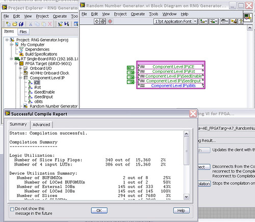
After that the output indicator comes with CLIP, compilation to fail...

NEITHER sbRIO-9601
LabVIEW 8.6.0
LabVIEW FPGA
Windows XP (32-bit, English)
No conflicting background process (not Google desktop, etc.).Usually a "trimming" error gives to think that there are a few missing IP. Often, a CLIP source file is missing or the path specified in the XML file is incorrect.
In your case I believe that there is an error in the XML declaration:
1.0
RandomNumberGenerator
urng_n11213_w36dp_t4_p89.vhd
fifo2.vhd
This indicates LV FPGA to expect a higher level entity called "RandomNumberGenerator" defined in one of two VHDL files. However, I couldn't see this entity in one of two files. If urng_n11213_w36dp_t4_p89 is the top-level entity, edit the XML to instead set the HDLName tag as follows:
urng_n11213_w36dp_t4_p89 Also - in your XML, you set the 'oBits' music VIDEO for output as a U32, however the VHDL port is defined as a vector of bits 89:
oBits: out std_logic_vector (89-1 downto 0)
These definitions must match and the maximum size of the vector CLIP IO is 32, so you have to break your oBits in three exits U32 output. I have added the ports and changed your logic of assignment as follows:
oBits1(31 downto 0)<= srcs(31="" downto="">
oBits2(31 downto 0)<= srcs(63="" downto="">
oBits3(31 downto 0)<= "0000000"="" &="" srcs(88="" downto="">Both of these changes resulted in a successful compilation.
Note: The only compiler errors when you add the flag because otherwise your CUTTING code is optimized design. If the IP is instantiated in a design, but nothing is connected to its output, it consumes all logic? Most of the time the FPGA compiler is smart enough to get it out.
-
Cannot send DIO siganl using the LabVIEW FPGA Module and MyRIO
Everything works when no FPGA is used. If the circuit and harware work.
However when targeting module FPGA MyRIO, acquiring data and processing the work and the signal to the engine's 'sent' (visible when executing Hightlight is on). But there is no tension on the DIO ports used. FPGA projects includes VHDL code.
Do you know what could cause this problem?
You must control the OID in the FPGA.
-
LV FPGA workflow nested CLIP w / NI SMU-6591R
Hello
I develop an application on a NI-SMU-6591R Board. My installation also includes a SMU-1085 w chassis / controller 8135.
Goal: set up a VHDL project prior to the Commission of 6591R. Given that the application requires access to 2 ports Mini SAS HD and the VHDCI connector on the front of the 6591R (physical front) a CLIP nested is the only option here, isn't it?
I am quite new to the LV FPGA framework. In order to understand the flow of the whole project, I would like to launch a trivial VHDL design on the 6591R: a D-FlipFlop edge triggered w / Syncronous reset. I have attached the the D - FF and the wrapper of CLIP VHDL code.
I would like that (1) a little (LV::boolean/VHDL::std_logic) to pass the port D of the D - FF VI (name FDF/D) and (2) drive the LEDs of the Board of Directors according to the signals of outputs (FDF/Q and FDF/QB). Also, I want to read (3) the same outputs (FDF/Q and FDF/QB) back to the VI flying two Boolean flags.
Following the white paper OR, I have:
- Managed to create a XML interface of the import VIDEO Wizard, import the 2 files VHDL (D - FF and its packaging).
- Selected the ELEMENT created in the IP-level component properties window. The LV_DATA_IN (host2fpga) and LV_DATA_OUT (fpga2host) I/O appear in the project tree, under the CLIP icon.
- Created a new VI under the FPGA device with an infinite while loop. Inside the loop, I dropped the LV_DATA_IN and the LV_DATA_OUT e/s and connected with a control (to LV_DATA_IN) and two indicators (of LV_DATA_OUT).
First of all, why in a simulated execution mode, the behavior of the indicators is totally random? They are not connected to one of the connectors 6591R...
Linking the FPGA VI, he reacts to any change in the control LV_DATA_IN button... Why?
The design works as expected in Vivado both in behavioral simulations and post-synthese.
Before asking here, I tried to understand it on my own. I have read all the documentation that I found on campus (I got access to LV Core1, Core2, Core3 and FPGA course material) and on the internet.
What is still missing me?
TY for your kind help!
-
Hello
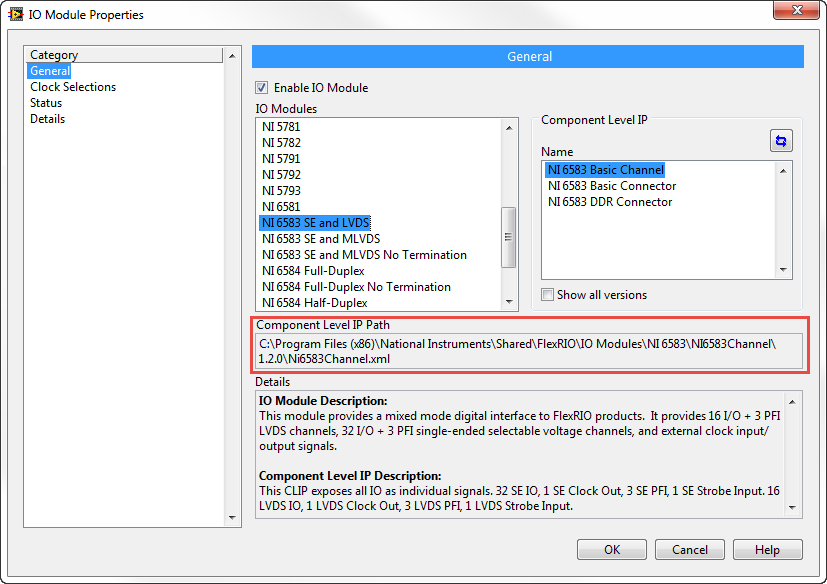
I am currently using SMU-7966R with module of e/s-6583.
For my application, I need to access IO with imported vhdl design FPGAS. As a result, I try to use a CLIP half bridge.
Following the tutorial process NOR, I imported a CLIP half-bridge (for example Ni6583ConnectorDdr.xml). But I can't find a way to instantiate this CLIP I heard the message:
"This statement of the CLIP is a CLIP half bridge and it cannot be instantiated in a socket."
Documentation OR I haven't found example for customizable CLIP but not how instantiate a socket, and then a half-bridge CLIP. You can define more precisely this procedure?
Thanks in advance,
Roman C
Hi Roman,.
To CLIP half bridge, it means that it must replace one of the sections CLIP material in the project, in this case the module. This means that when you choose which module you are using, you choose your CLIP instead.
I think that he can come in the entry, it must be stored in the right place on the disk to appear in lists in the dialog box. You can see the path of the existing CLIPs from the dialog box:
See you soon,.
James
Maybe you are looking for
-
Satellite Pro L40 wireless channel selection
I have a Realtek 8187 b WLAN in my Satellite Pro L40. I have the latest drivers installed with xp pro, but can't set the channel everything but 10. How can I change the channel when I get the message that the channel range must be 10-10. This just do
-
How can I get a new tag that displays information from computers at the bottom of my laptop?
I took the sticker that comes at the bottom, how do I get a new one?
-
Windows Voert niet meer correct af. PC gaat niet meer ITU through market: close. Deze is maar nog alleen af you door Aan/ITU knop some seconden ingedrukt Pickwick you houden. Daarna start niet meer op en hij wordt devising PC not door een keuze van
-
Vsphere-Windows failover cluster replication
HelloNeed help to replicate Microsoft cluster at 2 knots. I know that vSphere replication is compatible with virtual RDM so will change to virtual RDM physica, but the controller SCSI ROW of nodes have buses sharing (Physics) is enabled. How to repr
-
MiniMac Yosemite - can it run Dreamweaver CS3?
I recently bought a MacMini Yosemite - running and trying to get my Dreamweaver CS3 to run on it. It seems that since the specifications that it should run, but when I tried to install from the CD, nothing was in the Dreamweaver folder - just a gree