Simultaneous release of digital waveform at different frequencies - cDAQ-9174 with two 9477 maps error-50103
Hello
I'm working on a project that requires two outputs digital signals at different frequencies. Frequency of the phase 1 is about 1 kHz and is modulated on and off to a pace that will change during the execution of the program. Wave 2 passes from 1 kHz to about 6 kHz while needing to be pretty accurate to the tenth of a Hertz.
Initially, I tried to manage the simultaneous output of signals at different frequencies using a single task on a single 9477 daqmx in a cdaq-9174 chassis. As far as I know, the best way to get a specific frequency in a waveform output is to set the sampling frequency up to 2 times the frequency of the wave that is generated and generate a waveform that is given to each clock cycle. This works very well when it comes to a gesture, but I was unable to get the frequency of the modulated wave (wave 1) remains constant when the frequency of wave 2 modified or vice versa.
I have a few other modules lying around (another 9477, 9403 and 9476) and I thought I would try another task running on a separate module. I find myself receive error-50103 message if I add these modules to my cdaq chassis and run one of the waveforms of a task set to run on the add-on. Is there a way to bypass this error? I guess it would cause by running two digital output on the cdaq-9174 tasks at the same time, but it seems to me that this wouldn't be a problem with an additional module.
How can I have two outputs digital signals, running at the same time, maintaining their independent frequency frequency of the clock of the other sampling rate changes. In addition, because the wave 1 is enabled and disabled at a defined frequency, I use it to set the number of samples to write when you write a range of waveforms in the module (when generating these two waveforms on the same module).
I'm sorry if the explanation was difficult to understand. I've attached an example of error 50103 lifting. This isn't really a part of my project as a whole, but it is the easiest way to reproduce the error.
Thank you
Hi awol.
I have a follow up for you. You encounter the error because the cDAQ chassis has only a timing engine of. You will not be able to perform simultaneous tasks of the call by the hardware. Please see the following knowledge base: http://digital.ni.com/public.nsf/allkb/5E0B829E50ADE1BC86257AC50062B2D2
Mike
Tags: NI Hardware
Similar Questions
-
Generate digital waveforms of high frequency
Hi all
I have some problems. Today, I am generating several digital high frequency waves with my DAQ (PCI-6251) card. The duty cycle of the waveform must be adjustable.
The required frequency is 100 kHz.
To do this, I have tried several solutions:
(1) I used counters in the acquisition of data to generate waveforms, and it worked fine. However, I have only two counters. In my application, I need to at least three waveforms with different cyclical report;
(2) I used a 'loop' and structures 'case' in labview to build the model of waveform and then feed them to the digital I/o. However, the problem with this solution is that the frequency of the wave generated cannot be high.
(3) I used a 'digital' generator in Labview to generate waveforms and then feed them to the digital I/o. In this case, the time base is from an external source (200 kHz). However, with this solution, the cycle is not adjustable.
Please give me some advice on how to make these waveforms. Your assistance is appreciated.
OK, so I may be wrong, but after mucking around for a bit, I realized that the regeneration should be automatic - in other words, if you a pattern to the right and then just leave your VI work in a while loop, you will find that the generation is continuous. Discover the correlation dig write metered in the finder for example Labview. You can leverage this as you get the cyclical report you are looking for. You can split the signal down what you write a single period consisting of a series of 0 and 1. In other words, if you want a wave of 100 kHz with a cycle of 20%, you write a pattern of digital waveforms a 1100000000 at the rate of 1 MHz. Using this technique, the resolution of the cycle will be limited by the on-board clock speed (80 MHz = 0.125%).
Let me know if this makes sense - I am unable to reproduce this on my desktop and have never had to do this before.
Cheers, Matt
-
Increase the frequency of sampling on the cdaq 9174 with neither 9212
Hi all!
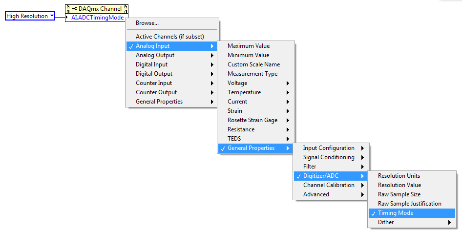
I am trying to increase my sampling rate on my nor 9212, that I use with a cdaq 9174 and LV 2015. Apparently, the sampling frequency depends on the time of conversion and can be changed between the high speed, the Best 60 Hz rejection, best 50 Hz rejection, and high resolution. (see http://www.ni.com/pdf/manuals/374358a_02.pdf, page 6). My maximum sampling frequency is 1.8 Hz, which indicates the use of the mode of synchronization of high resolution
I found this documentation explaining how to change with a crio:
http://zone.NI.com/reference/en-XX/help/373197D-01/criodevicehelp/cRIO-9212_rt/
However, I can't change it when the module is not in my project with my cdaq. My question is: How can I change the conversion without a crio time?
Thank you very much!
X0N0
Hi X0N0,
There is a DAQmx property for this:
You are welcome!
-
Different frequencies of signalexpress with oscilloscope
Hello
I'm new to the signal processing. I am facing some difficulties to measure the signal of a sensor of acoustic emission for my project. I use the PXI-6115 module with 1042 q and terminal block is TB2708. I used AI0 and AI1 for main signal and trigger respectively. I acquired the signal of 6115 in SignalExpress (v3.0) and convert to linear spectrum (Hanning window) and conversion of RMS with RMS on average 200. Same parameters are used in the oscilloscope (LeCroy LC564DL) too. I plugged the two signals of oscilloscope as well as for comparison. I saved data from the spectrum of SignalExpress and oscilloscope and plotted. You can see the graph as an attachment. It's totally different. Why is it so?
And one more thing, that is if I disconnect my connector NI DAQ system, spectrum in oscilloscope changed in amplitude at a certain frequency and vice versa.
Thank you in advance.
Myo
My apologies for the late reply. I've been sick for a few days.
I generated an amplitude 1V (2V peak-to-peak), 100 kHz, 10MS/s 20ksample sine wave to help to create an analog Signal. I treated it with the power spectrum using 200 linear medium with RMS algorithm. Value at 100 kHz - 3dB, as expected and as it should.
However, at a given time in the process, forced SignalExpress my frequency of 100 kHz to 50 kHz (probably due to a shift of frequency and the number of points). This would result in what you see. Check your project to see if this has happened to you. If so, you would get - 350dB to 100 kHz (essentially a pure signal noise floor) and - 3 dB to 50 kHz.
-
Table 1 d of digital waveforms
I have a table 1 d of digital waveforms and I need to work with the data. I can't get the 'mass' to work with any function table or any other type of function also.
I need to be able to convert these so I can find a particular value in the table.
Thank you.
So you're just trying to get inside the matrix? Use a loop For or an Index Array node.
-
Frequency of measurement with cDAQ NI 9402 chopper
Hello world
I'm new in the world of the cDAQ and try now just get a frequency of a TTL signal output chopper. I confirmed 23 Hz frequency on an oscilloscope. It's a nice clean 5V square wave, but when I try to measure the frequency in labview using a VI (dig frequency of continuous measurement) example, it comes to expire. Trying to look at the entrance of the signal in express shows signal an incompatible digital signal that is around 3 Hz and clearly the result of the port being interviewed for entry too rarely. The final objective is to get this work with the labview vi PLL is a detector lock in the amplifier, but first of all, I have to be able to measure and to read correctly this frequency.
My hardware is a cDAQ-9174 with a 9402 OR for use with the digital input. I don't know it's important, but the 9402 module is in slot 3 and I'm on channel 0. The software is labview 8.2 with DAQmx 9.1. Is there some timing issue material or the definition of I'm missing here? Any help is greatly appreciated, thank you!
Hi Skaboss,
Counters have multiple terminals (source, the door in and out), which map to separate on your NI 9402 PFI lines. For the measurement of the frequency, the default input terminal depends on the method of measurement (low frequency, high frequency, wide range). Here's the relevant section of the NOR-DAQmx help (which is on the Start Menu):
Connections of signals C series for counters
The following table lists the default input for various measures of meter terminals. You can use a different line of the PFI for one of the input terminals. To edit the entry PFI for a measurement, use channel NOR-DAQmx attributes/properties.
NEITHER 9402 and NI 9435 (4 channels)
Measure Ctr0 Ctr1 Ctr2 Ctr3 Number of edges Edges: PFI 0
County Executive: PFI 2Edges: PFI 3
Branch Count: PFI 1Edges: PFI 1
Branch Count: PFI 0Edges: PFI 2
County Executive: PFI 3Pulse width measurement PFI 1 PFI 2 PFI 3 PFI 0 Duration/frequency measurement (low frequencies with a meter) PFI 1 PFI 2 PFI 3 PFI 0 Measure of duration/frequency (frequency with two counters) PFI 0 PFI 3 PFI 1 PFI 2 Duration/frequency measurement (wide range with two counters) PFI 0 PFI 3 PFI 1 PFI 2 Measure semiperiod PFI 1 PFI 2 PFI 3 PFI 0 Measurement of two-Edge separation Departure: PFI 2
Stop: PFI 1Departure: PFI 1
Stop: PFI 2Departure: PFI 0
Stop: PFI 3Departure: PFI 3
Stop: PFI 0Measure of position A: PFI 0
B: PFI 2
Z: PFI 1A: PFI 3
B: PFI 1
Z: PFI 2A: PFI 1
B: PFI 0
Z: PFI 3A: PFI 2
B: PFI 3
Z: PFI 0Alternatively, you can override the default with the CI. Freq.Term channel property.
Brad
-
Digital output with NOR-9401 in cDAQ-9174
Hello
I have a cDAQ-9174 with an e/s digital NOR-9401 module. Now I want to output Digital signals on line0:3
$line0: Boolean 1 time = 10ms
Line1: Boolean variable 1 time = 20ms
row2: Boolean variable 1 time = 30ms
line 3:20 pulses (period = 250us, duty ratio = 0.5) after a time = 40ms
the value of line0:3 must be Boolean 0 after 45ms
Can someone let me know what I need to work to solve this please?
Thank you all for your help.
Concerning
Bing
Thank you Christian for your quick replay.
I have some experience in programming of microcontroller with C. I learned LABVIEW for about 1 month and followed a lot of demons in line and tutorials. I know that nodes DAQmx Data Acquisition screws and fundamental property.
As I said at the beginning on the $line0, lin1and line2, they serve to control the relay in my circuit. 10ms could be controlled with the OS clock. Pulse of line3 series is used for IGBT gate signals, which is the critical moment. I want to use the clock machine to accurately control line 3 and synchronize at the same time the pulse with analog inputs from an another two NI9206 modules in the same cDAQ chassis.
I just want to know more on the digital line demand signal relay output and a correlation between the line of analog input-synchronized finished pulse output. Waveform diagram is locked.
Thank you.
Bing
-
static/digital waveform output and low frequency measurement of voltage - SMU-6358
Hello
1. I have an attached VI [digital_voltage_output] who must generate a logical true or false static state in the output of the device/port0/line1 Word to say. When the VI works I click the button several times, but nothing happens to the port0/lines1.
2 such a thing [digital_voltage_waveform_output_square] if I'm trying to generate a digital waveform to pin the same with the waveform generating VI. If I connect a waveform chart to the output of the generator function VI, then the chart will show me the good waveform I want, but still nothing is written to the text file.
3. I have read the manual for the X series cards, but it remains unclear for me a little how to things of the road in LV I have a measure of the frequency measurement VI low frequency that I downloaded. It offers me the ports for the supply frequency - ctr0, 1, 2, etc. As far as I'm concerned the PFI ports are responsible for these types of actions. How can I find out the LV that I want to connect say ctr0 and pfi0? »
I use LV 8.6.
Thank you
Kriváň
Hi Kriváň,
The problem you had with the choice of a specific digital line as a physical channel, is that the control that was previously used in this example was created for a data acquisition task that uses a whole port rather than a specific line. I was able to overcome this problem by removing the control and recreate. The control now gives you the option to choose the specific digital lines e.g. port0/PXI1Slot2/$line0.
I was also able to overcome the error of-200802 you mentioned. I was able to do this in a real constant of wiring at the entrance to auto-start the VI DAQmx writing then remove the DAQmx beginning the subsequent code VI. The modified code is attached.
I hope this helps.
Best regards
Christian Hartshorne
NIUK
-
I use the outgoing/incoming analog DDK with the DAQ 6341 SMU map.
The examples, for example aoex5, show a single timer (method outTimerHelper::loadUI), but the example shows the DMA loaded with same size of vector data.
There is a comment in the outTimerHelper:
 call rogramUpdateCount, which implies that memory sizes different pad per channel can be used.
(the comment is: switching between the sizes of the various buffers is not used)
Nobody knows what should be the format the DMA buffer for data from multiple channels with different frequencies?
For example, we want a0 with a sinusoid at 1 kHz and a1 with a sine wave of 1.5 Khz. What looks like the DMA buffer?
With the same frequency for each channel, the data are interleaved, for example (ao0 #0, ao1 #0; ao0 ao1 #1, #1,...), but when the frequencies for each channel is different, what the stamp looks like?
Hello Kenstern,
Data are always intertwined since each card has only a single timing for each subsystem engine.
To AO, you must specify the number of samples that will be released to the AO. You also specify the number of channels. Because he didn't is that a single engine timing for AO, each AO will be channel will be updated at the same time to update clock tick. Data will be interlaced exactly as shown in the example because each channel AO needs output at each tick of the clock to update. The data itself can change depending on the frequency you want to copy.
kenstern wrote:
For example, we want a0 with a sinusoid at 1 kHz and a1 with a sine wave of 1.5 Khz. What looks like the DMA buffer?
With the same frequency for each channel, the data are interleaved, for example (ao0 #0, ao1 #0; ao0 ao1 #1, #1,...), but when the frequencies for each channel is different, what the stamp looks like?
In your example, you must come with an update rate that works for the two waveforms (sine waves of 1 and 1.5 KHz). To get a good representation of a sine wave, you need to update more than 10 x faster than your fastest frequency... I would recommend x 100 if possible.
Update frequency: 150 KHz
Channels: 2
Then create you stamps that include complete cycles of each wave you want to produce based on the frequency of update. These buffers must also be of the same size.
Buffer 1: Contains data for the sine wave of 1 KHz, 300 points 2 cycles of sine wave
Buffer 2: Contains data for the sine wave of 1.5 KHz, 300 points, 3 cycles of sine wave
You can Interleave them as before. When the data are performed through the ADC, they are out different sine waves, even if the AO channels are updated at the same speed.
-
Several channels with different frequencies
Hello
I use card NI USB-6221.
The C API using, I need to generate 6 digital output channels, with frequencies of diffrenet and Heavy duty.
To be more precise, the 2 are totally identical, but I need them to be reversed, and the other 4 are similar to another, but should be shifted in time (I.e. There is a delay between each of the channels).
I used the 2 channels of CO that the USB-6221 takes charge for the first two signals, and it works very well (the two signals are synchronized and are reversed).
Now I need an additional 4 channels for the other vague square.
I saw an articale NOR by JohnP web site with the title:
Generate multiple channels of digital output with different frequencies and Heavy Duty
The following example shows how to create and generate a digital with the non-regeneration wave form so that you can change the frequency and the duty cycle on the fly with the M Series DAQ hardware X. The example uses output digital rather than counters to achieve this, so if you need more output than the available counters, it would be a good option (Note: on the materials of the M series an external sample clock must be provided, this may be caused by one of the counters if you want).
that seems to be exactly what I need, but the examples are for LabView which I did not.
Can someone explain how to do this with the C functions?
Best regards
Danny.
Hey Danny,
The important thing to note is that you can clock of arbitrary digital waveform (up to 1 MHz on the 6221). The real data acquisition programming is pretty easy once you have the waveform. My Example LV used LabVIEW Base generating function VIand then converted to a digital waveform to generate the signal from each channel.
The functions of LV helped tremendously with to achieve the waveforms to be updated on the fly (the basic function generator keeps track of phase for you).
If you do not need to be updated on the fly, then the construction of the waveform in C should not be too bad. For example:
P0.0 [1 1 1 1 1 1 1 1 1 1 0 0 0 0 0 0 0 0 0 0] * 1
P0.1 [0 0 0 0 0 0 1 1 1 1 1 1 1 1 1 1 0 0 0 0] * 2
P0.2 [0 0 0 0 0 0 0 0 0 0 1 1 1 1 1 1 1 1 1 1] * 4
P0.3 [1 1 1 1 1 0 0 0 0 0 0 0 0 0 0 1 1 1 1 1] * 8
[9 9 9 9 9 3 3 3 3 3 6 6 6 6 6 12 12 12 12 12]
The table above U8 would give you 4 output waveform of 50% duty cycle at Fs/20, shifted 90 degrees to eachother. The lines would be p0.0 by p0.3 (the bit rate of the U8 corresponds to what line goes high).
Best regards
-
Can someone tell me how to extract a part of a digital waveform?
I am trying to extract a part of 2 analog waves (using the http://zone.ni.com/devzone/cda/epd/p/id/4149 for example) analog signals is synchronized with a digital waveform. I need to extract the same portion of a digital waveform. Can someone tell me how to add the digital extractor in the example above?
Hello
Here's your extractor example slightly modified in order to add the digital data extraction.
The principle is exactly the same, the tricky part is how to get digital data which is different from analog data.
You can also add nodes property to identify the value read on the analog graph sliders on the digital chart.
Kind regards
-
Generating analog output signals 4 with different frequencies
Hi all
I was trying to say to generate 4 different signals at different frequencies
1. first waveform is a sine wave with 5000 Hz,
2. other with 8000Hz,
3. third, one is a square with 25 Hz waveform and
4. fourth one with triangular waveform 50 Hz
all waveforms must be generated simultanoeusly.
I tried to generate with the task unique analog output and sample clock (clock rate is 100000). Cross in scope that I see only 5000 and 8000 Hz we generated correctly and the rest two waveforms show the incorrect frequency.
I guess that's due to the frequency of high clock to sample for more low frequencies for ex 25 Hz and 50 Hz. If I reduce the clock rate to get the lower frequencies properly so I can't generate frequencies higher correctly. (there's a clsh between frequencies and the clock frequency)
Is it possible to use DAQ board master sample clock and its magnitude downward revision (everywhere where it is necessary for each waveform separately) to generate all the signals at different frequencies at the same time in a single task?
-
PCI, I / AO at a different frequency
Hello
As a newbie, I met a problem when I tried at the entrance and the analog output signal at a different frequency.
I followed PID-control - Multichannel .vi to build a control program, so input/output can be synchronized. However, the project requires that the frequency of I be tenfold of the AO. I could re-write the while loop to make the output value constant for 9 of 10 cycles. However, in my view, it is simplest way to do.
Anyone provide an example?
Thank you in advance.
Sincerely yours
Ming
lmuri wrote:
Hello
As a newbie, I met a problem when I tried at the entrance and the analog output signal at a different frequency.
I followed PID-control - Multichannel .vi to build a control program, so input/output can be synchronized. However, the project requires that the frequency of I be tenfold of the AO. I could re-write the while loop to make the output value constant for 9 of 10 cycles. However, in my view, it is simplest way to do.
Anyone provide an example?
Thank you in advance.
Sincerely yours
Ming
Hello Ming!
Please use the Forums of NOR. You'll be happy to know DAQmx allows what I/O tasks such as these to be not run not only at the same time, but at different rates.
The problem with the solution that you have imagined is that this implementation will remove the delegation of tasks to the hardware level, and your program would become software-driven; This becomes a problem when you perform tasks of acquiring data at very high speeds as it becomes limited to the speed of your operating system (OS).
You can coordinate your tasks to operate synchronously and perform the output and the acquisition at different rates by creating a maintask. This means generally that you configure a task by DAQmx that keeps a clock frequency and you create tasks that use this clock frequency, or a division thereof, to exploit to their own individual frequency. This facilitated not only the execution of DAQmx tasks synchronous but also provide a material entirely focused on the solution of performance maximimse.
Thanks to LabVIEW, if you go to help > examples find to open the Finder of example of OR. If you are browsing material input and output > DAQmx > synchronization > multifunction > Multi - multifunction - Synch Dig read write with Counter.vi, you will find an example of how to set up a counter as a master of the task to control the operation of operation both a reading and writing . (This example shows a digital but implementation may be easily replaced by analog).
By setting the meter to the maximum frequency rate that you will require for your task (in this case, the speed at which you want to copy values) and apply it to the output of the SampleClocktask, you will drive the clock output task with the counter as the clock source. You can then use the meter as the source of the SampleClock for the task of entry, however to set the rate at any division of the driving frequency. In the case of your example, you can set the bit rate to 0.1 times the frequency counter to acquire a 10th of the rate.
If you want to acquire at the same rate, but only to retrieve values on the 10th of the speed, this same solution can be configured to produce instead a trigger to return an acquisition in the buffer. With a master synchronizing the task, the possibilities are endless!
I hope you find it useful, and if you need a precision more do not hesitate to let me know. Have fun with your DAQ!
-
How to control each channel of the signals emitted by the generator of digital waveforms?
Generator has digital waveforms of 8 channels. I need to generate two different signals for HSDIO. How to change and control two different ways? In addition, how to translate pinout of the PXI-6541 to channels? I need pin 1,3,29 and 31 control signal individually.
Thank you!!
You need to combine your personal data in a table. The digital waveforms is simply a numeric representation of the binary table. It always boils down to bit 0 of each element of the array will channel 0 (or the first string that you specify in creating dynamic channels). The next bit goes to the next channel. My last post is very clear. To display the table in binary, right-click on a table element, then select the display Format, then select binary. You can also right click on the element, select Visible, then select Radix Show to display the small b before the number. One last thing, in the display Format window, uncheck the box next to the minimum field width to use. Then set the digital just below zone 8. Then select Pad with zeros to the left in the box below.
You should not use waveforms up to what learn you more about how the HSDIO operates on the input data. It is not difficult to combine waveforms, but it is not as clear as it is using an array of U8, U16 or U32.
Trying to explain further. The first number to be written to the HSDIO will have this effect: Bit 0 (LSB) of the number is written to the first HSDIO string you specify. Bit 7 is on channel 8, you specify. If you specify no 8 channels, the bits download ignored. If wiring in a certain number will produce only a single bit on each channel. In other words, the number has already combines the bits of all channels that you specify. Combine you do nothing yourself. Return to my photo on my last post. By wiring in a table, you cause a binary model must be generated.
I hope that is more clear.
-
Same result for different frequencies?
Hi all
I'm new to labview and the communication kit, so I'm trying to test the examples.
When the example of 'Rx Continuous Sync or Async' opening and it works I get the same output on the "power spectrum".
i'm checking different frequencies in the range of 1.2 GHz to 6 GHz.How is it possible then that there is nothing transmitted? -> checking with the android application for wifi channels (channels 1 to 8 are used, all others are not...) and yet labview gives me the same result... (attached file = 2 GHz, the other is a comparison of the 5 GHz, 2,412 GHz and 2,484 GHz)
material:
NEITHER USRP N210 (rev 4)
CBX 1200-6000 MHz Rx/Tx (40 MHz)
Antenna VERT900connecting via gigabit
PC: W7 64 bit, i7-2600 to 3.4 GHz, 4 GB RAM
Thanks in advance
Hey insiderbe,
I did some research on the Ettus forum and found the following:
https://lists.gnu.org/archive/HTML/discuss-gnuradio/2010-08/msg00237.html
https://www.Ruby-Forum.com/topic/214890I suspect that the IPS you see on 0Hz is the DC offset that is introduced to the ADC of the USRP N210. We can confirm this by removing air and closing the RX. If the tip is still there, it's a feature of the analog input circuit.
Brian of Ettus recommends tuning your frequency slightly out of your signal of interest and using a high pass filter to remove DC offset. I recommend looking at the second link for more information.
With respect to obtaining the value of art through many different frequencies, I think that it is a property of the antenna used. The VERT900 is valid from 824-960 MHz and 1710-1990 MHz. can you listen to one of these groups and test your power, even if you have a known signal? You have another USRP generator or a function to generate a known signal?
https://www.ettus.com/product/details/VERT900
My last concern use the N210 with the CBX in LabVIEW Communications. According to the Readme, it's an unsupported hardware configuration, which means that R & D has not tested the configuration, and we do not know how the configuration will occur.
http://download.NI.com/support/softlib//RF/NI%20USRP/15.0/niUSRP_readme.html
Thank you for this post!
Kind regards
Maybe you are looking for
-
Questions on Satellite L300 - 11 c (PSLB0E) WLAN
I bought a L300 - 11 c and after a week, I got a blue screen when you try to pass of the Wifi network. After a restart of the laptop working again. A few days later I got this blue screen again and I couldn't get my WLAN online. It seems that there i
-
turn off the ringer only on hp 640 fax
How can I disable only the ringer and not all the sounds on the HP 640 FAX?
-
Skype does not appear in the notification iOS5 Center
Hi all I use the latest version (3.5.0.454) of Skype on my iPhone 4S and I can't find the Skype app around the Notification Center of iOS5! It isn't yet on the list "notification Center". I tried to restart, reinstall and everything. The application
-
Hi all It is a question of Windows: is there a way to go in my application (when run as an EXE file) if it has been launched by the user (click on the EXE file) or if the application was launched by the OS because it's in the boot? Thanks in advance
-
want to 4500: HP envy 4500 print only not with the iMac
I have a 4500 desire connected to a new imac. When I send documents to the printer and check the print queue, it says it has connected to the printer and print, but nothing happens. Any idea what's going on?