periodic waveform generation complex FPGA (PXI-7852R)
I would like to create a complex periodic wave (digital) with my PXI-7852R.
After checking the article here on the generation of periodic waveform with cRIO and then for a few hours trying to get this software to work on my fpga (PXI-7852R) I'm not much closer to making it a reality.
I bet that someone with more experience could some conversion not fast enough... Notice to lovers?
Thanks in advance!
Tags: NI Software
Similar Questions
-
Waveform complex of FPGA (PXI-7852R) Lock-in Amp.
My main goal is to create a lock-in that compares complex signals (not only sine, square, etc.) point by point.
I have demonstrated that I can use DDS to create complex waveforms of reference.
Now I want to read an analog input and compare (i.e. multiply and integrate) the acquis of signal with the reference signal.
Attached below is my attempt. I changed the DDS to produce a sinusoidal signal for testing purposes. I proved to myself that the sinusoid of reference is correct (I wired it to an AO and checked) and sine wave sampled is correct (I also have it wired to an AO and checked).
Unfortunately, the output of the average does not take into account the phase of the two signals. If I change the Ref wave phase or the acquired signal or freq, the output of the average remains the same... random osccilations from + 2 to-2 V. The average averaged for the number appropriate to points, as long as the number of points is less than 70 ks (convert to 'wave form cycles' host vi).
I suspect that there is a mistake in my 'mean.vi '. I created it by changing the average VI found on the FPGA palette. I replaced the 'high through put' multiply by the digital multiplication (from the top through put does not work on the objectives of the CR). Everything else is the same.
Any suggestions?
Thanks in advance
Proj1.PNG a screenshot of my FPGA code and host mean.vi
Found the problem!
The product of two signals is nonsense. Reduce the amplitude of the two signals cleaned straight up. Apparently something was saturate...
-
FPGA (PXI-7852R) Square Wave DIO
I need to improve the noise to the DIO square pulse pulse width. With my current code (attached .png) I see 25 ~ ns jitter on the front coming down from the impulse (I have the trigger on the rising) with my oscilliscope. This Jig is present even with only a single output square wave (i.e., I delete the other square wave generators).
Any ideas how to improve the fidelity of pulse width?
Thanks in advance!
25 ns is the period of your clock to 40 MHz, the jitter is unavoidable at this clock frequency. The DDS square wave algorithm produces a very precise frequency over time, but cannot control the speed at which it is called to update.
If you set the clock of the loop to a greater frequency of derived clock, you shoot the Jig by the same factor. Right-click on a 40 MHz clock embedded in the project with the FPGA target and choose new clock derived from FPGA. You may need to experiment a bit to see how high you can set the clock frequency without introducing sync in compiling violations; new targets will allow higher clock rates generally. Set up your single cycle timed loop to use the derived clock and don't forget to update your average square configuration with the new clock frequency.
-
I created two pieces of code that run as desired independently. It creates a sine wave, reads analog input waveform and concludes the relative phase. The other piece of code creates three waves with independent settings (freq, duty cycle, etc.). When I try to put them in the same vi only the first code runs. Square waves are not generated from the second code.
Any ideas why?
I wouldn't be surprised if my problem was something to do with the SCTL which is part of the code of the square wave. I tried to put the SCTL inside the loop on the other code and square waves have not yet been produced.
attached is a file .png to my code.
Thanks in advance!
I found a work around... I changed the IO nodes and how I expect to knit square waves. See the attached png file for more details
Thanks for the comments everyone!
-
Hello
I currently have a PXI-7852r, and I try to get the data from the FPGA for post-processing of vi map. I wrote a simple loop to retrieve the data from the fpga, but when I move it to the host vi I start getting time values. For example, I say the card wait 50 usec between samples and it does but when I run the host vi my timing goes haywire. I guess what I'm asking is how can I get the card data sampled at usec 50 to the post-processing step.
Any help would be appreciated,
The first example I mentioned above does not use a timed loop, but you should probably be able to replace the while loop with a timed loop, set the clock to 200 kHz and still compile fine.
Depending on whether you want to raise or not your acquisition, on the side of the host of VI may need to be slightly modified, but the provided VI must be a good starting point.
Post your screws if you encounter some unexpected problems (or better yet, the project, as in the example, since there are a few definitions of FPGA coming along if you just post on the screws).
-
Generate a digital waveform like memory on PXI cards
Hello
I'm looking for a way to send a large digital waveforms using a PXI digital signal generator. I saw DIO HS cards, but their memory is smaller than the files that I want to transfer. My understanding is that the PXI backplane bandwidth 132 MB/s. So, I shouldn't be able to stream a digital signal from the memory of the card that is slower than the CPU? For example, 50 Mbits / second (equivalent to only 6.25 MB/s)? However, I think I understand after reading their textbooks is that you cannot continuously transmitting a large waveform of the processor memory file, you must transfer the file to the memory of Council first and then transfer that out.
Does anyone know if there is a way to have a flow of digital signal generation card an arbitrarily large directly from memory to the processor of digital signals? Or, what is the fastest card of pxi digital signal generation that does not require the storage of Council first files?
Thank you
Isaac
Hello Isaac,.
Take a look at the following area developer.
NOR-HSDIO Stream from disk (generation) using Win32 file IO
Note that you will not be able to take full advantage of the maximum rate of update HSDIO devices, because the data must be transferred in a bus. Some other considerations are the width of the data as well as the HSDIO device you select, which may depend on other requirements not related to the size of file or waveform (for example the standard voltage or whether you need hardware compare). For more information, take a look at the developer following items area.
Data streaming of Architectures in the PXI systems
The use of National Instruments Logic Analyzer and generator of test patterns SolutionAdvanced features of e/s high-speed digital devices White Paper Series
-
Digital waveforms of SPI with PXI-6552
I am trying to follow the following tutorial about the PXI-6552 module: http://www.ni.com/white-paper/3671/en.
This is the example that I am referring:
You can also use the data Active event to control the relative delay between the response data and the side assets of the sample clock. For example, you can export the active data on PFI 1 event and send it to the PFI 2, which can be configured as the source of Start command acquisition, as shown in Figure 8. You can export the generation of sample DDC CLK clock out and adjust the STROBE acquisition sample clock.
Figure 9 shows a LabVIEW program that configures and outwardly carries the data Active event and the sample clock. The functions marked with an arrow carried out additional system requirements.
Hello MrHappyAsthma,
I'm looking at your code, and I see that you have two sessions of acquisition while the example has an acquisition and sessions of a generation. This could be the reason for the error.
The digital data control are done right click on the front panel, then go on modern > I/O > digital data.
I hope this helps.
-
How to get tilted periodic waveform in labVIEW?
Hello
I want to draw a waveform that has range of 0 to 360 and have a frequency of 50 Hz. the logic that I used in my code is like:
50 HZ = 0.02 seconds.
360/0.02 = 18000 (means multiply each sample to 18000 to get inclined wave that offers an amplitude in the range 0 to 360)
values go from 0 to 0.02, not accurate, and I multiply each step with 18000 to get the desired line.
1. take the current stage.
2. If step is > 0.02
then start from scratch
3. other (less then or equal to 0.02 seconds, then)
Multiply step with 18000
but I do not get the desired response. kindly help me, I'll be very grateful to you
Kind regards
Brassart ahmed
Why not use the function of the ramp signal? Check the range of signal generation.
Also, looks like you're wanting to generate an output signal. If so, you need to put your data in the buffer and to let the jury AO manage the timing of release. Windows has too much jitter timing to do what you want.
Mike...
-
generation of impulses PXI-6602
I am new user and I got pxi 6602 iwant to generate a 5 3.5ms amplitude 2.5 kHz and 2.5 offset I probably need to use 2 meters can someone tell me which wires I need to connect on CBS 68 device and how ican write this program?
Thank you for helping meIt can generate a ttl which means a pulse of 0 to 5 volts. If that fits your definition, then it will work.
-
Create simulation FPGA PXI card?
Hello
I wonder if it is possible to emulate a FPGA card (like 7854R) to evaluate the possibilities of Labview FPGA?
Thank you.
This is possible and maybe more. This whitepaper is a good start to http://www.ni.com/white-paper/7445/en#toc2
-
Waveform generation continues in C/C++, application example
I am looking for one or more examples of analog output in which a waveform is generated on the fly. for comparison, all of the examples with NOR-DAQmx constantly shipping and way repeated output data; I would like to be able to edit the output values. non-renegeration may be the Member of (non-obvious) phrase that I'm missing in my research. suggestions, please?
This seems to be what I'm looking for:
http://zone.NI.com/DevZone/CDA/EPD/p/ID/4872
only in c / c++ instead of labview.
Hi David,
This example should be useful - this looks like what you want to do.
DAQmx - continually generate tension - no regeneration - LabWindows/CVI
The part of the acquisition of data is:
Configure
DAQmxCreateTask("",&taskHandle);
DAQmxCreateAOVoltageChan(taskHandle,chan,"",min,max,DAQmx_Val_Volts,);
DAQmxSetWriteAttribute (taskHandle, DAQmx_Write_RegenMode, DAQmx_Val_DoNotAllowRegen);
DAQmxCfgSampClkTiming (taskHandle",", rate, DAQmx_Val_Rising, DAQmx_Val_ContSamps, 1000);Write data
DAQmxWriteAnalogF64(taskHandle,bufferSize,0,10.0,DAQmx_Val_GroupByChannel,data,&written,);
Start the task
DAQmxStartTask (taskHandle));
Write data continuously in a loop
so that {(gRunning)
DAQmxWriteAnalogF64(taskHandle,bufferSize,0,10.0,DAQmx_Val_GroupByChannel,data,&written,);
}Clear task when finished
DAQmxClearTask (taskHandle);
Data written on your task must follow the pace it's be clocked what you receive a buffer overflow error (i.e. the data array must be large enough so that you write enough data by loop iteration). Writing DAQmx is a blocking call, so if you try to write more data space available in your loop output buffer will wait here until space becomes available and he finishes his writing or the specified timeout is reached.
Best regards
-
Hello
I'm working on the attached VI for the acquisition of the temperature. The program displays the data acquired on the two graphs in real-time and save it in a file when the user click on the dedicated button.
I want to add a feature which save the data in the file automatically every # measure (user-defined) and reset the graphics. I tried to do (see the lower right in the second while loop), but all previously recorded data is deleted and replaced. How can I write the new data after the old man? I don't know if I explained, I can give you more details if you need.
Thank you!
Your Subvi file writing have an entry called Append? By default, they are fake and will create a new file when you do not have a constant connected to it.
You must connect a real constant to these inputs, so it will add the new data in the file.
Is there a reason that you have two while loops? Why do you use of so many local variables? You can have race conditions seriouis past that might lead you to duplicate data, or data loss.
-
FPGA device configuration, package and speed grade.
Hello.
Where can I find the news of grade package and the speed of the FPGA inside of the PXI-7842R? I ask because I want to build a project XPS in the Xilinx XPS and program needs this info.
I followed the example in the "how to use designs based on Xilinx Microblaze with NI LabVIEW FPGA 2009 and the R-series modules". There, he gives the info for the specific FPGA (PXI-7852R and PXI-7953R) they use. It's a Virtex5, ff676, xc5vlx50, level-1 speed, but the authors do not mention where one can find this info.
Thank you
Bill.
Nevermind, found the info in this way:
Instruments\LabVIEW national 2010\Targets\NI\FPGA\RIO\R Series\Pxi-7842r
Bill.
-
FPGA wave sinusoidal generation discontinuity
Hi all
I have a question about the generation of sinusoidal waveform FPGA: the generated waveform has unknown non-periodic discontinuity. I want to know where it was generated and how to solve it.
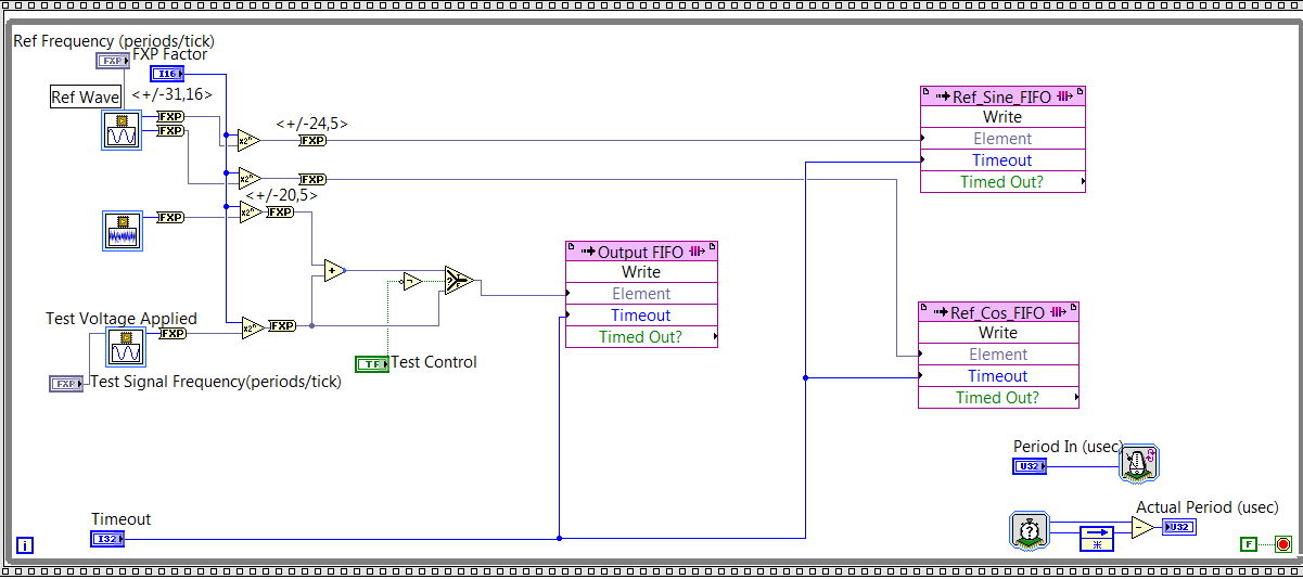
As you can see on my FPGA code below, I generated reference signal - a wave of fishing and a cos wave by using the function of 'generation of the sine wave. Then I write the data to their corresponding FIFO and the sampling rate is controlled by "Period In (usec)" and it is set at 20. Thus, the sampling rate is 50KS/s.
Fig. 1. Code generation of FPGA sin wave
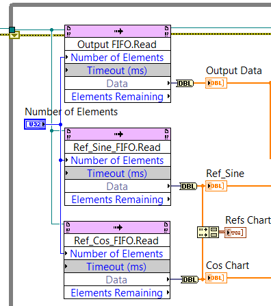
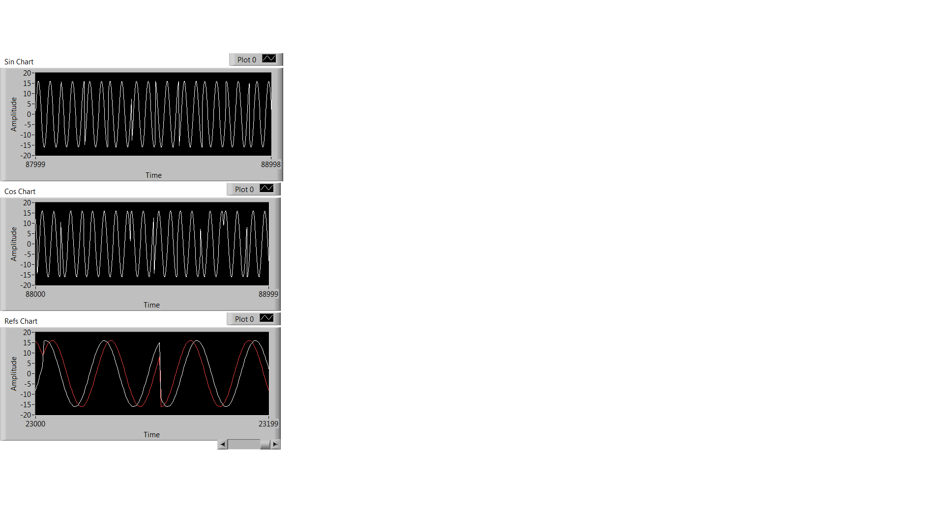
At the level of the RT, I observe the data through the code illustrated in Fig. 2, and what I observe is Fig. 3. Three graphics from top to bottem are: result of the sine, cosine wave result, sin / cos wave shown using the same chart.
Fig. 2 RT level Code
Fig. 3 Sin / Cos waves are the result
Everyone has the same problem ever or any input on what has caused this?
Thank you!
Kind regards
Doris
Hello
Thanks for responding! I think I solved this problem. What's happened is that the execution time for the rest of my code of RT level is longer than the duration for the FIFO to be filled, so the code FPGA that writes data in the FIFO to wait to get code RT to finish. FIFO data are not time continues because of this reason.
Kind regards
Doris
-
Problem with the generation of multi-sinus wavefrom of random phase using PXI-5412
Hello
I am trying to generate random phase multi-sine waveform using the PXI-5412 14 bits 100 M/s AWG on LabVIEW8.0.
The version of LabVIEW8.0 for the PXI-5412 comes with a sample VI on multi-tone waveform generation. When I tried with a different combination of frequency and amplitude, there is no problem with the sample VI.
Because I need the phase to be random for each frequency component, I had tore the tone cluster containing 3 elements, i.e. frequency, amplitude and phase, which feeds the generator of signals, and rebundle the cluster with elements of reading a CSV file by using a loop, a fixed value amplititude and a number of random phase of the frequency generated by a random number (formula lournies elements (: pi - 2pi x r). When the waveform multi-sinusoidale generated on the PXI-5112 100 MHz Digital Oscilloscope, it was pointed out that the waveform would change with the tested frequency range. However, the amplitude of the wave is always ~1.4V (guess that's always default to 1 V x sqrt (2)). There is no question also when testing the same combination of frequency and amplitude by using sample VI without modification.
Please find attached the VI of the sample, snatching up to the version and the CSV file I used. Is there something wrong with the table 1 d of the cluster of 3 elements that I built and assembled causing the signal generator to ignore the value of input amplitude and, possibly, the input value of the same phase (as it seems that the amplititude is always set to the default)?
The other question that I found on the two sample VI and ripped version is on the news of sampling. The waveforms appear on digital Oscilloscope PXI-5112 always default to 10 cycles no matter how changed the sampling frequency and the number of samples. For example, if the frequency is 10 Hz, sampling frequency is 1000 Hz, and I put the number of samples to 10000. I'm supposed to get 10000/100 = 100 cycles. However, I could see 10 cycles no matter how, I changed. What should be the correct way to change the number of cycles?
Really appreiciate your help and advice. Thank you.
1 phase unit is in degrees (-180 to 180), no - pi pi.
2 standardize Waveform.vi always normalize your amplitude of the signal. You can remove it to use your desired amplitue, but must make sure that it is not above 5412 spec.
Maybe you are looking for
-
Web page of Demonoid does not connect in Firefox
Firefox refuses to open the page Web of Demonoid, with error msg "unable to connect. Firefox can't establish a connection to the server.Other browsers open OK.Tracking solutions in the knowledge base of Mozilla and other sites (which seems to be a pr
-
ServoApp appears after Windows Vista starts
"ServoApp" appears on the taskbar after starting Window Vista, what is it, how can we that to solve this problem?
-
Bluetooth won't connect to Macbook?
This weekend I've flattened my phone using the CCP but still have a problem with Bluetooth. I love the smart lock and work function, I want to use my work Macbook Pro as a device. The phone and Mac will pair without problems, but seconds after matchi
-
How to change permission to all users in the custom dashboard
Hello I created the new personalized dashboard I want to give access to my colleagues to give the permission to change. Please let me know how to do this? Thank you Vivek
-
Identification number of blackBerry Smartphones?
Hello I just got my Blackberry I brought on ebay but when I turn it on it asks to enter a PIN. How do you get around that because I can't get a response from the person that I got on ebay. Please help, I am so excited to start using my new phone. Tha