Loops FPGA (PXI-7852R)
I created two pieces of code that run as desired independently. It creates a sine wave, reads analog input waveform and concludes the relative phase. The other piece of code creates three waves with independent settings (freq, duty cycle, etc.). When I try to put them in the same vi only the first code runs. Square waves are not generated from the second code.
Any ideas why?
I wouldn't be surprised if my problem was something to do with the SCTL which is part of the code of the square wave. I tried to put the SCTL inside the loop on the other code and square waves have not yet been produced.
attached is a file .png to my code.
Thanks in advance!
I found a work around... I changed the IO nodes and how I expect to knit square waves. See the attached png file for more details
Thanks for the comments everyone!
Tags: NI Software
Similar Questions
-
periodic waveform generation complex FPGA (PXI-7852R)
I would like to create a complex periodic wave (digital) with my PXI-7852R.
After checking the article here on the generation of periodic waveform with cRIO and then for a few hours trying to get this software to work on my fpga (PXI-7852R) I'm not much closer to making it a reality.
I bet that someone with more experience could some conversion not fast enough... Notice to lovers?
Thanks in advance!
-
FPGA (PXI-7852R) Square Wave DIO
I need to improve the noise to the DIO square pulse pulse width. With my current code (attached .png) I see 25 ~ ns jitter on the front coming down from the impulse (I have the trigger on the rising) with my oscilliscope. This Jig is present even with only a single output square wave (i.e., I delete the other square wave generators).
Any ideas how to improve the fidelity of pulse width?
Thanks in advance!
25 ns is the period of your clock to 40 MHz, the jitter is unavoidable at this clock frequency. The DDS square wave algorithm produces a very precise frequency over time, but cannot control the speed at which it is called to update.
If you set the clock of the loop to a greater frequency of derived clock, you shoot the Jig by the same factor. Right-click on a 40 MHz clock embedded in the project with the FPGA target and choose new clock derived from FPGA. You may need to experiment a bit to see how high you can set the clock frequency without introducing sync in compiling violations; new targets will allow higher clock rates generally. Set up your single cycle timed loop to use the derived clock and don't forget to update your average square configuration with the new clock frequency.
-
Waveform complex of FPGA (PXI-7852R) Lock-in Amp.
My main goal is to create a lock-in that compares complex signals (not only sine, square, etc.) point by point.
I have demonstrated that I can use DDS to create complex waveforms of reference.
Now I want to read an analog input and compare (i.e. multiply and integrate) the acquis of signal with the reference signal.
Attached below is my attempt. I changed the DDS to produce a sinusoidal signal for testing purposes. I proved to myself that the sinusoid of reference is correct (I wired it to an AO and checked) and sine wave sampled is correct (I also have it wired to an AO and checked).
Unfortunately, the output of the average does not take into account the phase of the two signals. If I change the Ref wave phase or the acquired signal or freq, the output of the average remains the same... random osccilations from + 2 to-2 V. The average averaged for the number appropriate to points, as long as the number of points is less than 70 ks (convert to 'wave form cycles' host vi).
I suspect that there is a mistake in my 'mean.vi '. I created it by changing the average VI found on the FPGA palette. I replaced the 'high through put' multiply by the digital multiplication (from the top through put does not work on the objectives of the CR). Everything else is the same.
Any suggestions?
Thanks in advance
Proj1.PNG a screenshot of my FPGA code and host mean.vi
Found the problem!
The product of two signals is nonsense. Reduce the amplitude of the two signals cleaned straight up. Apparently something was saturate...
-
Hello
I currently have a PXI-7852r, and I try to get the data from the FPGA for post-processing of vi map. I wrote a simple loop to retrieve the data from the fpga, but when I move it to the host vi I start getting time values. For example, I say the card wait 50 usec between samples and it does but when I run the host vi my timing goes haywire. I guess what I'm asking is how can I get the card data sampled at usec 50 to the post-processing step.
Any help would be appreciated,
The first example I mentioned above does not use a timed loop, but you should probably be able to replace the while loop with a timed loop, set the clock to 200 kHz and still compile fine.
Depending on whether you want to raise or not your acquisition, on the side of the host of VI may need to be slightly modified, but the provided VI must be a good starting point.
Post your screws if you encounter some unexpected problems (or better yet, the project, as in the example, since there are a few definitions of FPGA coming along if you just post on the screws).
-
Synchronization between two periods loops FPGA
First of all, I appreciate the forums here and have read a lot of interesting topics. This is the first time I can't solve it with research and I hope for your entry.
Information:
I'm using LabVIEW 2009 f3, PXI-1033 with the PXI-7813R.
Problem:
In my FPGA program, I have two loops, where you need to run as fast as possible (has) and the second just quickly (B). Has turns 20 MHz to 40 MHz and B . These are for the two loops limiting speeds. B cannot run faster and Has should not run more slowly.
Loop has captures the sensory information and integrates data as many loops as indicated by the user. When completed, please send a trigger to B, which calculates the new position information and sends it to the machine. Only at certain times, B must achieve something and said nothing to the rest of the time.I thought of two ways, but doesn't work for me.
(i) with the help of a Boolean trigger. As in a loop, the Boolean value of A can become true and switches to the next loop to false, B is not capture all the triggers and a 50% chance of getting the triggers and isn't perfectly synchronized.
(II) using the occurrences. Sounds very interesting, but these are prohibited between the periods differently loops.
I played with many scenarios, but may not understand proper. Someone at - it suggestions?
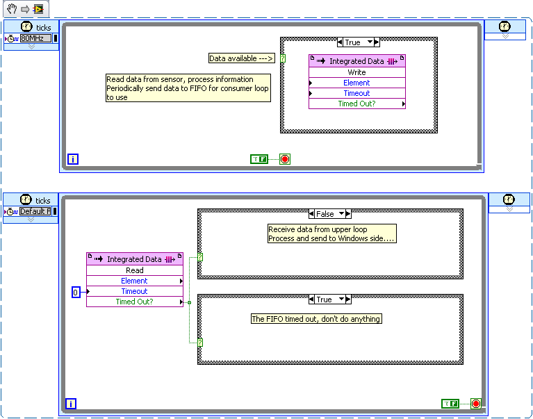
This seems to be a fairly simple producer/consumer scenario.
I would like to use a device worn FIFO to transfer data from the loop of producer (top) to the loop of consumer (bottom).
Depending on how often the producer generates data (each cycle or every nth cycle?) the case around the write FIFO structure will allow him to write only when your requirements are met.
The consumer loop reads the FIFO with a timeout of '0 '. When the FIFO is to expire, the consumer runs to the case which does nothing. When the FIFO does not expire, who processes the data and sends it to the side of Windows runs.
In my example, I used 2 structures of cases to illustrate the two different modes. In your code, you must use a single structure of matter.
There is no advantage to set a loop "sleep", even if no data exists on the FPGA. Because you are running in hardware and the non-profit CPU cycles these loops can operate simultaneously at no increase in the latency of a
-
Value of the loop 'For' pass before the complete loop - FPGA
Hello
8.5 LV, LV FPGA, PCI 7831-R FPGA Board
I got a cramp of brain on this one. I have a function (Arb. GIS read) that Im using to generate an arbitrary signal which I created in memory. I can't move to the value of data however. I don't know why I can not, its because it is nested in a "loop For" who runs indefinetly and updates only the value whenever it loops back to 'zero '. Ideas quick and dirty on how to use this value as it is being updated in the loop in my hand vi?
I've seen messages on the use of local variable 'Files' and property nodes, but I can not just give a sense the. Maybe because it's FPGA, something is different/no supported?
* My principal is 'control MicroMirror Arb. SP", look in the #4 case and the condition of"false. "
The 'Sub - VI' is called 'Arb Sig read RevB', and I'm trying to pass the variable 'Data' to hand while the loop For always runs.
Thank you!
-
Create simulation FPGA PXI card?
Hello
I wonder if it is possible to emulate a FPGA card (like 7854R) to evaluate the possibilities of Labview FPGA?
Thank you.
This is possible and maybe more. This whitepaper is a good start to http://www.ni.com/white-paper/7445/en#toc2
-
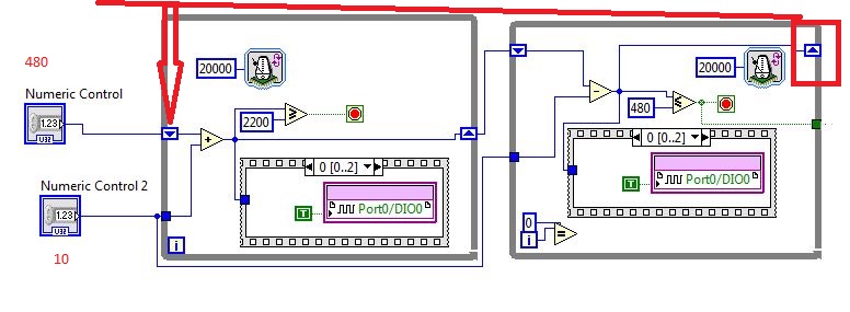
Recover the registry values to shift to another loop (FPGA)
Referring to the image above, all the two loops are inside a loop (not shown in image). Problem is im trying to run the digital command only once and use the value of the second loop after that. I tried many ways and don't have still no idea how... could someone help? Thanks in advance
augustg,
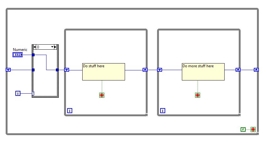
You could try to use a structure case to route digital controls in this movement register only on the first iteration of the outside while loop and in all other cases courses out of the second shift loops to register in the first case. Kind of hard to put into words, but something like this:
The structure box to the right that I added has a new case "Default". In this case, the value from the shift of the outermost while loop register is wired straight through. I hope this helps!
-
FPGA device configuration, package and speed grade.
Hello.
Where can I find the news of grade package and the speed of the FPGA inside of the PXI-7842R? I ask because I want to build a project XPS in the Xilinx XPS and program needs this info.
I followed the example in the "how to use designs based on Xilinx Microblaze with NI LabVIEW FPGA 2009 and the R-series modules". There, he gives the info for the specific FPGA (PXI-7852R and PXI-7953R) they use. It's a Virtex5, ff676, xc5vlx50, level-1 speed, but the authors do not mention where one can find this info.
Thank you
Bill.
Nevermind, found the info in this way:
Instruments\LabVIEW national 2010\Targets\NI\FPGA\RIO\R Series\Pxi-7842r
Bill.
-
Can damage the FPGA module if I connect accidentally two pins writing together.
My current configuration has a PXI chassis with two FPGA modules. Each FPGA module has an adaptation Module 6581 on that. I would like to test the signal through my system path by having the user to move some cables that would be a reason for a return to the other looping FPGA.
I fear, however, the risk of the user is not correctly as shown and somehow a channel available in writing that connects to another channel write-enabled. This damage to the FPGA or adaptation modules?
Hi Brian,.
Your concerns are correct. We never want to connect two pins that are output voltage. If two pins are outputs digital mistakenly connecting them together may damage one or both nodes in output since there is nowhere to flow the potential.
It is well to connect to two pins that read a voltage. If both pins running entry digital (reading of the pins), as there is no risk, nor pin would be likely to be damaged.
-
Deploy with fpga after change of chassis.
Hello
I'm running a project Veristand 2011 with an NI PXI-8109RT controller, a jury of NI PXI-7852R fpga and analog outputs 5 NI PXI-6733.
For development, I used a chassis PXI-1000 b.
Now, I have moved the system to a PXI-1045 chassis, and I can't deploy the project more.
It gets stuck the "start of the deployment group 1", and after a while, I get a timeout error (-307672).
The only way I deploy the project is to remove the FPGA of the nivssdf and remove the NI PXI-7852R of the chassis.
Of course I need to map FPGA, then... why the project will not deploy with it?
Thank you
Matteo
Hello Matteo,.
The chassis of 1045 (and other PXI chassis with a large number of slots) have several segments of independent PCI bus along the bottom of basket. By default, triggers are not shared between the segments.
So, if you want to synchronize all your cards, one solution is to put all cards in the same bus segment. If this is not possible, you will need to go to MAX and manually map PXI Trig 0 away from your card master sync everywhere for other bus segments. For more information on how to do this, see the following document:
Routing see PXI trigger in the bus chassis PXI crossover
Kind regards
Devin
-
FPGA - count inside a statement box
Hello, LV users - type of intermediary with the LV, fairly new to FPGA. I use LV2010 with the FPGA with a PXI-7852R RIO module. I have my working for all practical purposes, with the exception of a decision point FPGA application that is controlled by a simple integer (what-I-thought-should be). This integer that I tried first with registers at offset, then tried a knot of comments I've seen that had been used in the FPGA Debug.lvlib in 2008. STILL does not work! What happens in my code is as follows: whenever I detect the negative in my modulating wave, a Boolean value is True and penetrates in a case where it is appropriate to update my account by 1. Rather than be updated by one, it is updated the order of 10,000 or more, the same number each time + / a. Not sure where that number comes from. Count a tick maybe? It's a larger number if I slow down my modulating wave. No idea why this is happening? Even better, any ideas how to do a 'simple' metering works as expected? Thanks much for any help.
Out of curiosity, when the SaddlePtCount is true, only it prevents you from returning the 0.08 Hz, 0.0159 case? If you are not prevented from returning the case then your counter increment will continue to increase while your modulated signal is in the stubborn interval +-0.0003055. To check this possibility, you might reduce the scope delimited to say +-0.0001 to see if this reduces the number. Depending on the whether it works, everything you have need to do to stop the counter would be to have a "Triggered" local variable that is set to true the first time that the SaddlePt Boolean value is true. Then, if you wrap the feedback node increment in a nest additional cases, you could check the status of "Triggered" and if it wasn't it true value and leave the real case in the case empty structure. Therefore, the first time the County will be updated at each time consecutive that the signal is between stubborn in a given cycle, it will not change the County. The only other change would be to set the variable false "Triggered" when the SaddlePt is set to false.
Hope this helps,
Blayne Kettlewell
-
Laser digital lock with Labview FPGA?
Hello
Sorry to bother if you are not interested in this issue of digital signal processing. We are looking for a possible digital solutions to our problem locked frequency cavity closed-loop laser (see attached PDF file for more details). The goal is to flatten the PZTs transfer function (cancel the resonances and anti-resonances and their phase shift matching) in the frequency domain, in addition to the normal PID control. Input/output necessary voltage signals are small (we have our own amplifiers high power for the PZTs), and their bandwidth must be at least of 50 kHz (100 kHz would be optimal).
Among various OR hardware/software (DSP, FPGA, cRIO etc.), would anyone recommend a cost-effective solution for rapid prototyping?
Thank you!
I would like to look at the FPGA PXI cards nor 7854r. I rate of 750 kHz, 1 MHz AO. According to the involved treatment, you might expect between 200 and 750 kHz closed control loop. If the treatment is very intense, it's probably something less than 200 kHz.
That said, the key to these performance levels is not trivial and great care and attention to detail must be used in the coding of the FPGA.
Good luck
-
Adding personality to VeriStand FPGA
Hello
I am trying to add a personalized my VeriStand configuration FPGA. I use PXI-7853R in 1044 with PXI-8110 controller chassis.
The FPGA model itself is running properly and the fpgaconfig file is modified. The fpgaconfig and the bitfile are added to the propper directory. Now when I want to add it as a target FPGA, I get the following error:
***********************************
LabVIEW: File not found. The file could be
moved or deleted, or the path may be incorrectly formatted for the
Operating system. For example, use- as Windows path separators: on Mac OS
X, and on Linux. Check that the path is by using the command prompt or
File Explorer.=========================
NOR-488: The non-existent GPIB interface.
C:\Documents
and All Users\Documents\National Instruments\NI VeriStand
2010\FPGA\PXI-7853R HighSpeed Interfaces.lvbitx***********************************
I checked
but the http://Digital.ni.com/public.nsf/allkb/2FA525A8585A92E9862566EE002A3755 was not able to address the issue.
I enclose a few screenshots to give an image of my installation.
p.s. I'm not planning to use the GPIB.
Error 7 is a generic "file not found" error in LabVIEW. Unfortunately, I think the NOR-488 driver also uses the error code 7 for a GPIB interface to the nonexeistent, and the error description lists all possible sources. In your case, the error is due to a missing file and has nothing to do with the GPIB.
I re - check the bitfile name in the .fpgaconfig and verify that it is the path listed:
C:\Documents
and All Users\Documents\National Instruments\NI VeriStand
2010\FPGA\PXI-7853R HighSpeed Interfaces.lvbitxIf you can get the files .fpgaconfig and .lvbitx, we try here and I hope that give you the best guidance.
Maybe you are looking for
-
Enforcement myidol will not erase from my phone. I touched several times to "confirm" to remove the application and all of its data. I also restarted my phone several times.
-
put photos on a memory card, through my printer
I'm not sure I have the right forum. I am trying to put pictures on a memory card, the card will then go on my digital photo frame, I put the card in my printer which is smart Photo 5520 and I use windows 7, when I did it before with another printer,
-
Satwellite-A110-274 - sound does not
Recently my sound stopped working and I tried with headphones, but I can't hear anything. How will I know which is my sound card in Device Manager and if I need to download a new sound card that one do I need? Thank you!
-
Windows XP cannot create connection DSN ODBC in SQL Server to SQL Server
I create an ODBC SQL Server DSN connection on my desktop Windows XP domain. I select the system DSN and ADD. I select SQL Server, and it will return to the original system DSN screen. What's wrong? Has anyone seen this problem? There is anoth
-
I tried to load several updates that have failed in service pack (Microsoft.NET framework). They don't load and when I look at updates they say error 57. It seems stop take on IE9. Any solution to the problem? (In a few simple steps please. Thank you