PXI-7852r
Hello
I currently have a PXI-7852r, and I try to get the data from the FPGA for post-processing of vi map. I wrote a simple loop to retrieve the data from the fpga, but when I move it to the host vi I start getting time values. For example, I say the card wait 50 usec between samples and it does but when I run the host vi my timing goes haywire. I guess what I'm asking is how can I get the card data sampled at usec 50 to the post-processing step.
Any help would be appreciated,
The first example I mentioned above does not use a timed loop, but you should probably be able to replace the while loop with a timed loop, set the clock to 200 kHz and still compile fine.
Depending on whether you want to raise or not your acquisition, on the side of the host of VI may need to be slightly modified, but the provided VI must be a good starting point.
Post your screws if you encounter some unexpected problems (or better yet, the project, as in the example, since there are a few definitions of FPGA coming along if you just post on the screws).
Tags: NI Software
Similar Questions
-
periodic waveform generation complex FPGA (PXI-7852R)
I would like to create a complex periodic wave (digital) with my PXI-7852R.
After checking the article here on the generation of periodic waveform with cRIO and then for a few hours trying to get this software to work on my fpga (PXI-7852R) I'm not much closer to making it a reality.
I bet that someone with more experience could some conversion not fast enough... Notice to lovers?
Thanks in advance!
-
FPGA (PXI-7852R) Square Wave DIO
I need to improve the noise to the DIO square pulse pulse width. With my current code (attached .png) I see 25 ~ ns jitter on the front coming down from the impulse (I have the trigger on the rising) with my oscilliscope. This Jig is present even with only a single output square wave (i.e., I delete the other square wave generators).
Any ideas how to improve the fidelity of pulse width?
Thanks in advance!
25 ns is the period of your clock to 40 MHz, the jitter is unavoidable at this clock frequency. The DDS square wave algorithm produces a very precise frequency over time, but cannot control the speed at which it is called to update.
If you set the clock of the loop to a greater frequency of derived clock, you shoot the Jig by the same factor. Right-click on a 40 MHz clock embedded in the project with the FPGA target and choose new clock derived from FPGA. You may need to experiment a bit to see how high you can set the clock frequency without introducing sync in compiling violations; new targets will allow higher clock rates generally. Set up your single cycle timed loop to use the derived clock and don't forget to update your average square configuration with the new clock frequency.
-
Waveform complex of FPGA (PXI-7852R) Lock-in Amp.
My main goal is to create a lock-in that compares complex signals (not only sine, square, etc.) point by point.
I have demonstrated that I can use DDS to create complex waveforms of reference.
Now I want to read an analog input and compare (i.e. multiply and integrate) the acquis of signal with the reference signal.
Attached below is my attempt. I changed the DDS to produce a sinusoidal signal for testing purposes. I proved to myself that the sinusoid of reference is correct (I wired it to an AO and checked) and sine wave sampled is correct (I also have it wired to an AO and checked).
Unfortunately, the output of the average does not take into account the phase of the two signals. If I change the Ref wave phase or the acquired signal or freq, the output of the average remains the same... random osccilations from + 2 to-2 V. The average averaged for the number appropriate to points, as long as the number of points is less than 70 ks (convert to 'wave form cycles' host vi).
I suspect that there is a mistake in my 'mean.vi '. I created it by changing the average VI found on the FPGA palette. I replaced the 'high through put' multiply by the digital multiplication (from the top through put does not work on the objectives of the CR). Everything else is the same.
Any suggestions?
Thanks in advance
Proj1.PNG a screenshot of my FPGA code and host mean.vi
Found the problem!
The product of two signals is nonsense. Reduce the amplitude of the two signals cleaned straight up. Apparently something was saturate...
-
I created two pieces of code that run as desired independently. It creates a sine wave, reads analog input waveform and concludes the relative phase. The other piece of code creates three waves with independent settings (freq, duty cycle, etc.). When I try to put them in the same vi only the first code runs. Square waves are not generated from the second code.
Any ideas why?
I wouldn't be surprised if my problem was something to do with the SCTL which is part of the code of the square wave. I tried to put the SCTL inside the loop on the other code and square waves have not yet been produced.
attached is a file .png to my code.
Thanks in advance!
I found a work around... I changed the IO nodes and how I expect to knit square waves. See the attached png file for more details
Thanks for the comments everyone!
-
Trigger the FI - RIO 5641R and digitizer 5142
Hello
I am trying to generate a trigger of the my IF - RIO FPGA to start the acquisition on a table digitizer 5142. I want to do with the PXI line, but I don't have the same line in the e/s FPGA (PXIe_Trig0... PXIe_Trig6) and in the range driver (RTSI0.. RTSI6, PFI0... PFI2).
So, it is possible to do? If Yes, which line should I use?
Thank you
I found a PXI-7852R get tested. The problem was in the IF - RIO.
I found a vi in the 5641 driver to set the direction of the RTSI (entry or exit) lines. The default value is entered, now I change out and it works fine.

I wasn't a huge problem. I don't understand why we do it "manually" on this card, and why when we are simply changing the node FPGA read/write it does not change the meaning automatically.
Thank you for your help
-
FPGA device configuration, package and speed grade.
Hello.
Where can I find the news of grade package and the speed of the FPGA inside of the PXI-7842R? I ask because I want to build a project XPS in the Xilinx XPS and program needs this info.
I followed the example in the "how to use designs based on Xilinx Microblaze with NI LabVIEW FPGA 2009 and the R-series modules". There, he gives the info for the specific FPGA (PXI-7852R and PXI-7953R) they use. It's a Virtex5, ff676, xc5vlx50, level-1 speed, but the authors do not mention where one can find this info.
Thank you
Bill.
Nevermind, found the info in this way:
Instruments\LabVIEW national 2010\Targets\NI\FPGA\RIO\R Series\Pxi-7842r
Bill.
-
Deploy with fpga after change of chassis.
Hello
I'm running a project Veristand 2011 with an NI PXI-8109RT controller, a jury of NI PXI-7852R fpga and analog outputs 5 NI PXI-6733.
For development, I used a chassis PXI-1000 b.
Now, I have moved the system to a PXI-1045 chassis, and I can't deploy the project more.
It gets stuck the "start of the deployment group 1", and after a while, I get a timeout error (-307672).
The only way I deploy the project is to remove the FPGA of the nivssdf and remove the NI PXI-7852R of the chassis.
Of course I need to map FPGA, then... why the project will not deploy with it?
Thank you
Matteo
Hello Matteo,.
The chassis of 1045 (and other PXI chassis with a large number of slots) have several segments of independent PCI bus along the bottom of basket. By default, triggers are not shared between the segments.
So, if you want to synchronize all your cards, one solution is to put all cards in the same bus segment. If this is not possible, you will need to go to MAX and manually map PXI Trig 0 away from your card master sync everywhere for other bus segments. For more information on how to do this, see the following document:
Routing see PXI trigger in the bus chassis PXI crossover
Kind regards
Devin
-
FPGA - count inside a statement box
Hello, LV users - type of intermediary with the LV, fairly new to FPGA. I use LV2010 with the FPGA with a PXI-7852R RIO module. I have my working for all practical purposes, with the exception of a decision point FPGA application that is controlled by a simple integer (what-I-thought-should be). This integer that I tried first with registers at offset, then tried a knot of comments I've seen that had been used in the FPGA Debug.lvlib in 2008. STILL does not work! What happens in my code is as follows: whenever I detect the negative in my modulating wave, a Boolean value is True and penetrates in a case where it is appropriate to update my account by 1. Rather than be updated by one, it is updated the order of 10,000 or more, the same number each time + / a. Not sure where that number comes from. Count a tick maybe? It's a larger number if I slow down my modulating wave. No idea why this is happening? Even better, any ideas how to do a 'simple' metering works as expected? Thanks much for any help.
Out of curiosity, when the SaddlePtCount is true, only it prevents you from returning the 0.08 Hz, 0.0159 case? If you are not prevented from returning the case then your counter increment will continue to increase while your modulated signal is in the stubborn interval +-0.0003055. To check this possibility, you might reduce the scope delimited to say +-0.0001 to see if this reduces the number. Depending on the whether it works, everything you have need to do to stop the counter would be to have a "Triggered" local variable that is set to true the first time that the SaddlePt Boolean value is true. Then, if you wrap the feedback node increment in a nest additional cases, you could check the status of "Triggered" and if it wasn't it true value and leave the real case in the case empty structure. Therefore, the first time the County will be updated at each time consecutive that the signal is between stubborn in a given cycle, it will not change the County. The only other change would be to set the variable false "Triggered" when the SaddlePt is set to false.
Hope this helps,
Blayne Kettlewell
-
Hello
I have a pxi-7852r and I just installed labview 2011, but labview 2011 says that the device is not installed. If I go to labview 8.6, he sees the card without problems. Any help would be appreciated.
Thanks in advance
Hi efriday4455,
You have the NOR-RIO driver installed? You will need version 4.0 to the R with LabVIEW 2011 series map interface, and it must be installed after LabVIEW has been upgraded.
Kind regards
Peter W.
-
FPGA for PXI FPGA Communication
Hello
Due to constraints in/out, I need to find a way to send data between two different FPGA cards (specifically a 7852R and 7813R) aboard a chassis PXI-1042 q at a speed of about 1mech.
Does anyone know how this can be achieved / if possible (and if there is not a way to get 7 th / s on a single card).
Cheers, Ben
ports do you mean digital 12 bit groups?
When you say you want by 8 points, the number of bits in each point?
what you do in your loop of 80 MHz? Digital I/o? I don't think you can run digital at 80 Mhz.
using PXI lines, you create a bus digital multiline from the master to the slave. 1 clock, 1 sync. 4 data.
2 words per data row. up to 10 MHz clock rate.
However, NEITHER shown FPGA to hose FPGA using PCIe to NOR-Week of very broad band.
This seems more down your driveway. Do not know to what extent this tech was release but maybe in that neither can sound.
-
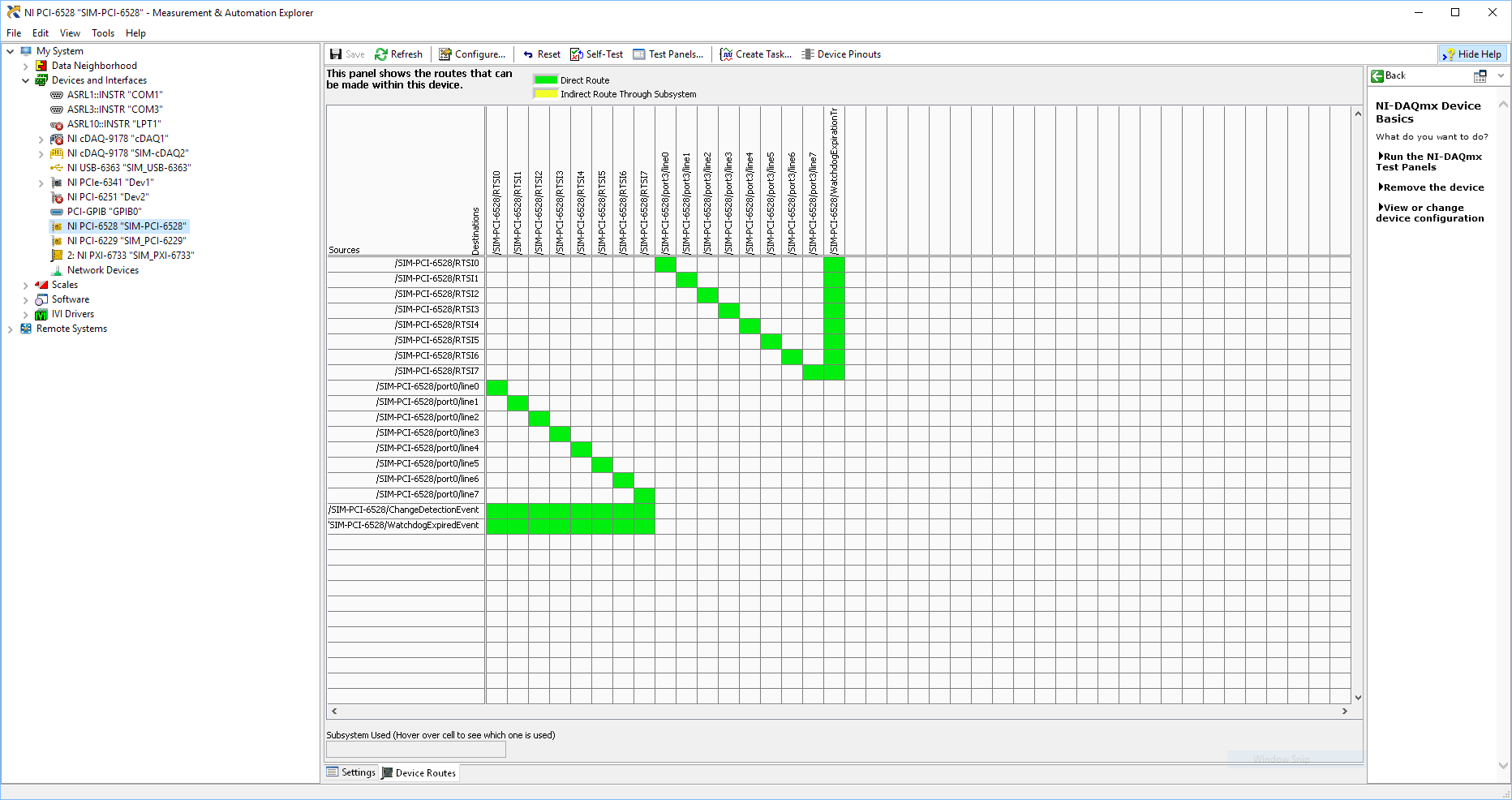
Using SMU 6612 to measure PXI-6528 pulsewidth channel - channel is not available.
Hi all
I use SMU 6612 card counter to measure the pulse width of the signals to PXI 6528 DIO card. These two cards are in the same chassis PXI (NI-SMU-1065). I could measure the pulse widths using the example LabVIEW 2013 Counter - pulse width of reading and (over) frequency example of .vi. However not all channels of the PXI-6528 map appear in the drop-down list of channels on the pulse width can be measured. Try to connect any other channel that those which are available in the drop-down list returns the error. On the PXI card port 6528 0,1 and 2 are entered ports and port 3-5 are output ports. I can measure the pulse on port 0, 3 width and line 0 port 1 and 4.
Can someone explain to me why don't see port 1 or port 2 channels in the drop-down list or force the VI to measure the width of pulse on these channels?
I can plug PXI-6528 external input channels SMU 6612 counter input channels and measure the pulse width, but if possible I'd like to avoid the external wiring between the 2 cards.
Probably not. Unless the routing plan is in fact reversed as it seems a bit sorta that. As stated on my system, you can route * of * a port of entry * to * RTSI, or you can route * of * RTSI * to * one output port. This does not make much sense to me, but that's what I see:
If the routing card * is * reversed, your only likely workaround without physical wire would be to generate impulses in question of port 3. It's pretty clear that 1,2,4,5-tetrachlorobenzene ports have no ability to interact with the bus timing, physical wiring would be the only option.
-Kevin P
-
PXI-1033 not detected until the pc is rebooted
We have a chassis NI PXI-1033 with a PXI-5114 and PXI-4072-PXI-6221, fist, that he had failed to recognize and install drivers for motherboards. The search in the knowledge base, I tried workaround by disabling the PCIe mode ' bcdedit/set pciexpress forcedisable' command and rebooted the pc. Then the system recognized and installed the drivers for all the hardware.
Disabled the PXI system at the end of the day. The next day, after activating the system, he did not recognize the hardware, returned changes to aid 'bcdedit/set pciexpress by default', then restarted the pc. Once again the material have been recognized.
I tried to change the configuration on the PC BIOS, without success. The PC is an ACP-4000 of Advantech. We need to restart PC after a cold start so he could recognize the hardware and load drivers.
Is this normal?
Concerning
The PC is under Windows 7 Pro. I searched on google for similar problems, where I found one where someone said that the culprit is that the chipset of the motherboard not give not the PCIe card delay what he needs on a start cold in order to be recognized. A reboot gives the time required and the card works.
-
Hello
I use a PXI-4070 DMM and DotNet "SoftwareTriggeredMultipointAcquisition" example
I want to trigger the DMM4070 with the AuxTrig entry to the front of the instrument.
This works very well, but how can I change the time out the of triigger?
It is now on 2000msec. I want to 10000msec.
When I us the example and do not trigger in the 2000msec I get error message saying:
ModularInstruments.NIDmm: The operation did not complete in time maximum allowed. Timeout: 2000mS.
Error code:-1074126845Thanks in advance
Wissam
Hello JaredRo
I can set the time-out period now.
Problem solved. Thank you Manny
With greetings
Wissam
-
PXI SFP 5105 configured Vs Acquisition VI
Hello
I recently started to use the NI PXI-5105 cards, I need to capture (noise level<20KHz) on="" top="" of="" my="" dc="" signal,="" i="" used="" software="" front="" panel="" to="" capture rising="" edge="" of="" an="" analog="" signal i="" was="" able="" to="" capture="" signal="" when="" it="" meets="" my="" trigger="" requirements="" same="" as="" configured="" acguisition="" example="" vi="" also="" vi="" recommended="" input="" signal freq="" ="" is="" 100khz,="" what="" changes="" i="" need="" to="" do="" in="" order="" to="" make="" this="" vi="" to="" trigger="" when="" the="" noise="" level="" on="" my="" dc="" signal="" exceeds="" certain="" point="" can="" anyone="" please="" help="" me="" with="" this="">
Thanks in advance!
Hey djo.
If I understand your description, the best sounds of relaxation as it can be a trigger of hysteresis with coupling AC trigger in order to eliminate the effects of your DC signal. You will then be able to adjust the amplitude of the noise that you are looking for as the level to which you want to trigger off. You can find information about the options available with the help of scanners trigger high speed OR under Fundamentals > trigger.
Maybe you are looking for
-
Spectrum X 360: Filling of spectrum X 360 after upgrade Windows 10
Hello It is a total disappointment for my upgrade from Windows 10! I bought my new spectrum X 360 a month ago, it was a pleasant experience using Windows 8 is very responsive and fluid. Since I've upgraded to Windows 10 earlier, everthing seems to be
-
How to coordinate the my music on my book of mac pro with my iPhone?
I subscribe to Apple music on my OS X, but cannot get it on my iPhone. What should I do?
-
Error 1406 when you install office on Vista
I can't install Office Professional 2007 or Visio 2007. It starts to install and then I get an error message 1406, implementation cannot write registry key value. Does anyone know how to fix this? Tomoe
-
BlackBerry Smartphone camera icon has disappeared from the home screen. How can I add it back?
My camera icon has disappeared from all my screens. If I use the search function, I can locate and use it. Why can't I put the camera icon, press the button of my bb and have an option "add to home screen"? I think that 'reset all my icons"can solve
-
How to guarantee a box has at least one active record
HelloI have a table block (two-elements of text with a box,I want to prevent the user from leaving the form unless there is at least one active record?