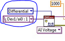
Pinout of the differential
I want to use the usb-6225 (screw terminals) in differential mode, but I can't find the pinout. Can you help me? Thank you
Here is a link to the specification. The list of the pins are at the end.
http://sine.NI.com/DS/app/doc/p/ID/DS-10/lang/en
In differential mode, it works in groups of 16. A0 is the + and A8 is-, A1 + and A9 - etc. A16 is + and A24 - etc.
Tags: NI Hardware
Similar Questions
-
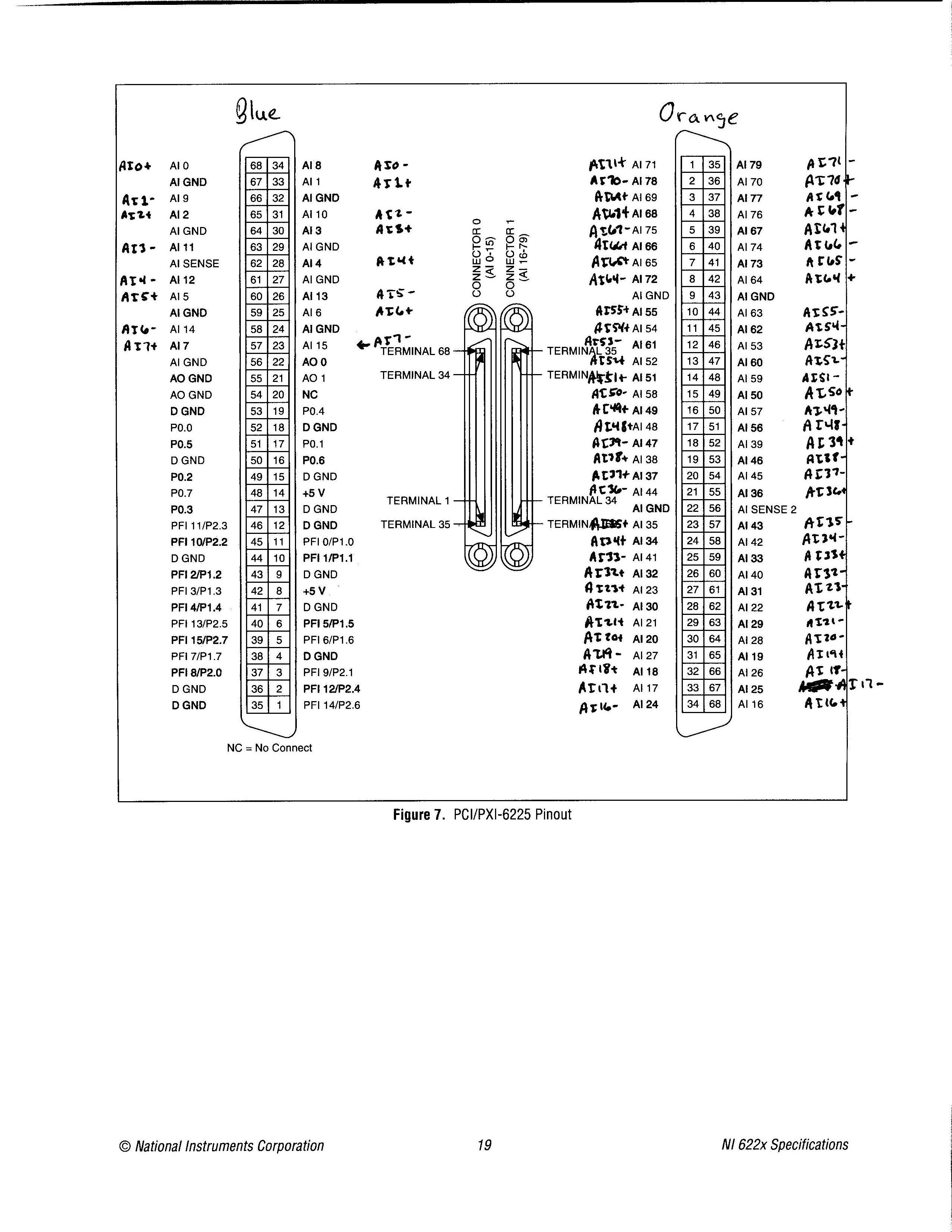
Pinout of the device from the PCI-6225 in differential Mode of I
Simple question: where is the pinout of the device for the card PCI-6225 for differential of analog input mode? I looked in the device list of the pins in MAX, in the NI 622 x specifications document and several other places, but I was not able to find it. I found the pinout for referenced asymmetrical measures, but no differential.
Related issue: most people use devices like the 6225 for no entries analog differential? So why in tarnation do many brand of material OR that upper and lower manuals, looking for the differential input version?
Thank you!
«Referring the number of pins would make it impossible to use the same code when you change maps DAQ.»
I'm not sure I followed here. Can you please explain a little further? Are you referring to the 1-68 0 connector pins and 1-68 pin connector 1? If so, I'm not sure, I followed. A different pinout may not change the code. If I had to replace a 6225 with another equivalent at least DAQmx device as many channels and the device number was the same, then I'd not change all the names of channel in the code, I? It would certainly change the wiring, which is precisely what I'm doing right now.
I know that the analog input channels look like ai0, ai1, etc.. My concern is later: where the jumps occur when you're in differential mode?
I have attached exactly what I would like to see in the documentation of ALL analog input device which allows the differential mode, only with the + and - channel names only and not the labels AI0-AI79. I couldn't find this photo any place, but rather had to laboriously calculate this pinout. If you know where to find this photo, I would be very grateful.
Thanks for the reply.
-
6225 DAQmx names for measurements of the differential pair
All,
I came across this post trying to find out if there was documentation to show who's analog inputs are coupled together and what name DAQmx controls call these pairs.
Messages from the author a drawing which I think is correct, but it is not an official document of OR. I'm looking for documents that says exactly what the name is for each pair during their use in a command DAQmx. I know literature 6225 AI0 and AI8 form a pair, and AI1 and AI9 are a pair, etc. etc. What I was trying to find, is documentation that shows that the name of each of these pairs, what I should do in the DAQmx calls during a differential measure. Currently, I am assuming that the AI0/AI8 pair is referred to as AI0 when the measure differential. I have just followed the list of pairs in the manual of the user from left to right and from top to bottom and naming of AI0 to AI39. I really was hoping that there was an official document that says what were the names of each differential pair.
Can you point me to the appropriate document or tell me that it is not an and that my assumptions are correct?
Thank you!
Doug
Doug,
There is not an official document similar to the one in the related post that shows the AI0 + and AI0-. The differential channel will always be referred to by the positive terminal. It doesn't matter what differential channel number it is. For example, the Channel 9 differential uses AI16 as the positive terminal. All configurations in DAQmx must be configured using AI16 in differential mode. The drawing was published is not official, but it is correct.
Kind regards
Danny F
-
How to set the differential input for personal iotech Daq/3000 mode
Hi all
I currently use personal iotech daq/3000 for the acquisition of data from the accelerometer.
I got readings of the analog input, while there seems to be no configuration for the differential mode.
What I have is:
selection of material - personaldaq / 3000:direct
Double click on, then:
Channel installation, there should be a selection of differential mode, I guess. But this is not.
Thank you very much
Alan
Have you reviewed the C:\Program Files\DASYLab 10.0\manuals\IOtech_DAQ_notes. PDF? Or the help of equipment?
The section of material assistance, using the analog inputs with DASYLab, includes pictures to show how to do this.
Open hardware driver.
Click the line Analog Input Channels, and then right-click to open the properties. This will display a dialog box that allows you to set the properties.
-
Does anyone have a pinout for the UMI OR AKD Drive Cable?
I make a motion controller with an NI 7350 card with evasion NI UMI-7774. I connect to the UMI-7774 to a drive Kollmorgan AKD with UMI OR AKD drive cable. This cable has a terminal of 20 pin block which I believe includes the home and limit switch signals, but I don't have a pinout of the UMI to AKD drive cable to verify this. Anyone know where I can get this pinout?
Thank you
Chris
Hi Chris,
Can be found on page 8 of the manual of getting started with the NI 7340/7350 and AKD Servo Drives Motors controllers the pinout of the connector terminal screws 20 pins of the UMI to AKD drive cable. Please do not hesitate to let us know if you have any other questions or is not what you are looking for.
Thank you
-
change output unique to the differential output end coder
I have single-end encoder. How can do it? change of single-end to the differential output.
Thank you
Oops... should read 'a circuit of converter more contained in the AM26LS31' instead of 'second half '. The AM26LS31 contains four circuits TTL converter for the conversion of the RS485 signal.
It is not necessary to connect unused inputs by the pull up resistors to the + 5V or directly to GND, the AM26LS31 resistance on pull-up on all inputs.
-
Z400: Z400 firewire pinout of the connector?
I noticed that the connector on the front panel 1394 connector 12 pin rather than the standard 10 pin. Does anyone know the pinout? It is not in the maintenance manual. Thank you!
Here is the pinout of the Z400 J13 1394 header. Keep in mind that it is looking at the head of the motherboard, and not the connector at the end of the connector to the front panel, which could be a reflection, depending on how you look at the connector.
The best way to determine the pinout is to use the keyed/missing pins as a refrence.
-
I need the list of pins for various connectors case-Strip pin, especially J24 but other multispindle those too.
Manual of Tyan S2915 Board for is a different version than that of poor quality that they OEM would be at HP for the 9400 and HP Tech Ref for the 9400 only provides pinouts for connectors well defined including pinout lie anywhere.
The connector of the Panel before xw9400 J34 (there is no J24) pinout, the mother, is map:
There are 2 key positions (lack of spindle) on pins 10 and 15. Use these empty pins to help identify the signals.
The pinout is very similar to other former workstations HP. A few tips:
-Pins 1 and 3 are for the harddrive activity led.
-Terminals 2 and 4 are for the power light. HP systems have back to back LED connected between these pins. A green is on and functioning normal and red lights (and flashes error codes) when there are errors.
-Connect a momentary between pins 5 and 6 switch will turn on the computer and off.
-Connection of a momemtary between pins 7 and 8 switch will force a system reset.
-PIN 9 is designated as + 5V, but it is powered by a 100 ohm pullup resistor to + 5V, so it will not provide a lot of power. FOR INFO.
-SPKR + and SPKR - are for the internal speaker.
Most of the other connectors xw9400 follow standards of industry, i.e. the IDE drive and floppy connectors.
Is there anything else you want to know?
-
create the differential signal of 6289
Is is possible to create a sine wave of differential on the output of the 6289? And how can I do this.
I created a differential DC 1V AO0 positive and negatives 1V AO1. Then measured on a differential input ADC signal, which is my DUT.
Now, I'm cutting the CMRR and wanr to use the DAQ6289 because I don't want to add another piece of equipment for the test plan.
Any ideas would be appreciated.
Please take a look at this example to see how to generate out of phase sine waves:
http://zone.NI.com/DevZone/CDA/EPD/p/ID/5001
Have a great day!
Daniel G.
National Instruments
-
Can someone help me with the pinout for an old matrix printer cable. The cable must have the HPIB/GPIB 24 centronics pins at one end and the usual printer centronics connector 36 pins to another. I have a DB-25 to centronics 36 cable I will be just cut the DB25 and solder the PIN 24. 8 data pins are not a problem. What I understand, it's where other signals should be terminated. I can't find where I can buy such a cable, so I'll try to build a.
Thank you
Jeff
Thanks for your reply Dennis.
Now that you have raised this theory, I can't be sure of myself now. I need to watch it, because, the plotter and digitizer are GPIB and the printer of the dam was probably too. It seems quite logical. Now I have to find a way to move forward.
Thanks again,
Jeff
-
problems with the differential measure at labview2010
Hello!
IM using a 6063e card to measure and labview 2010, but I had a problem that I can not understand.
AI0 is differentiall (w. AI8) and AI2 is also differential (and short circuit just for test purpose). I posted a bad image of my connections. I think this is the simplest possible differential configuration. A source of energy that can be set between 0 - 8v is connected to AI0. (yellow and Red wire coming out of the image)
With example signals "Acq Cont & chart voltage-Int Clk.vi" I can measure and read plot map DAQ. Sampling channel AI0 works as expected, the voltage can be adjusted between 0 - 8v. Sampling AI2 also works as expected, nothing happens when I change the voltage on AI0. BUT if I sample both AI0 and AI2 and plot the AI2 signals gets on 2v when 8v are threaded AI0. Is no mather what example or my own code, the example above is just a suggestion to illustrate the problem. I tried the card on a different computer running labview 7.1, and all 3 cases works. I also tested to replace the map with a 6062e and it shows the same problems. Can someone please test this on their installation of labview 2010, I want to know if my installation is weird or labview 2010 is broken somehow. Could be a driver problem with series 60xx cards?
I solved my problem by sampling AI0 AI1, AI2 and simply ignore AI1. Weird but this market so I suspect some sort of driver bug.
-
Problem: The differential mode, measure 1.4 V, USB-6009
Hello world
I am able to charge and discharge the two capacitors, individually.
I use the USB-6009;
Two capacitors, two charts, two analog inputs (AI0 +, AI01-) and (Al1 +, Ai1-);
I have configuredin differential mode; Ok
Problem:
When a capacitor is switched off, it measures 1.4 V
Try to correctly set the task - run the DAQ Assistant to create the task

Dev1/ao0 would be much better - Oh, and now that you take the wizard open-Do on the wiring diagram, it offers you

For the PREMIUM of 6009 task mode AI0 is + AI3 is - and you only reserve reserve explicitly AI0 (AI3 line is reserved by seleting the + line in the channel and the declairing it is differentiated)
And give the task/channel a significant name of "MyCap1Discharge" would be useful...
Now let's talk about your electrical engineering:
The input of the 6009 impedance is 144kOhms the resistance of discharge 1MOhm becomes useless as soon as you connect the control AI 6009.
-
Does anyone have the list of pins to make a Seraglio of cable to connect a pc to the switch LINKSYS SPS224G4?
Thank you!
Hello
The SPS224 console cable must be the same as the older the SRW series switch
OK, I took out my multimeter and checked the list of pins on my cable from the console that I use to connect to my SRW2008P.
My cable SRW2008P console on the two DB9 female connectors pinout is 1 to 1.
In other words easily DB9 female-female cable available with the following pinout.
1-------------1
2-------------2
3-------------3
4-------------4
5-------------5
6-------------6
7-------------7
8-------------8
9-------------9
Best regards, Dave
-
solve the differential equation
Hello
I m trying to solve a simple equation using euler vi. But I have not yet. the equation is:
(T) DH / DT = 1/A *(F-h/R). I m not understand what I need to plug on euler vi. I´v already took a look at the example of ode euler, but I continuously difficult. Please help me. Thank you.
I guess that your real goal is to learn to use Euler's method as it is a fairly easy to solve analytically ODE. Here's a quick example.
-
I have a HP with the following motherboard:
Then... I thought I remembered how it happened... I was wrong.
The jury essentially lies upside down in my case and I thought that the earth pin is on the right (left pin most of the three in relation to the motherboard) with the balance being the axis spdif PIN... I was half right. The centering PIN is the PIN spdif but plug the cable in this way in fact prevented the computer from power. I have no idea why, but that's what happened.
I reversed the cable and connected it left pin ground (PIN straight compared to the motherboard) and the spdif... centering pin machine lights up now and my audio works now again through my hdmi. I hope that my clumsiness may help someone in the future.


Maybe you are looking for
-
What is my password back to the bios administrator?
I have HP dv7-6b32us paviian, but I forgot my administrator bios password. After 3 trys, the code is 68350073. Thank you Minyong
-
Where are stored the documents downloaded to an iPad Air?
I downloaded a document from a Web site and can not find where it is stored. Is there a download folder or something like that?
-
stolen iPhone. Find my phone application has been put in place but does not work now. Probably the thief would have stopped data. If the thief installs their own sim card and the phone turns on, you will find my phone work.
-
Receiver ox800co13b error on my Outlook Express telling me that my C: drive is full when it is not.
receive messages ox800co13b I get the message followed ox800co13b of MSOE > DLL when my computer is turned on it relates to Outlook Express and tells me that m C: drive is full, when it is not. Can someone help please! Thank you Terry
-
Person to contact about payments
I tried the email. I tried this forum. I tried to open a ticket (it fails each time), to get help for my lack of money from sales of November. No response from RIM regardin my problem. Someone has an idea who or how to communicate with them about mon