Pinout of the GPIB
Can someone help me with the pinout for an old matrix printer cable. The cable must have the HPIB/GPIB 24 centronics pins at one end and the usual printer centronics connector 36 pins to another. I have a DB-25 to centronics 36 cable I will be just cut the DB25 and solder the PIN 24. 8 data pins are not a problem. What I understand, it's where other signals should be terminated. I can't find where I can buy such a cable, so I'll try to build a.
Thank you
Jeff
Thanks for your reply Dennis.
Now that you have raised this theory, I can't be sure of myself now. I need to watch it, because, the plotter and digitizer are GPIB and the printer of the dam was probably too. It seems quite logical. Now I have to find a way to move forward.
Thanks again,
Jeff
Tags: NI Hardware
Similar Questions
-
The GPIB-ENET/1000 commands reference
Hello
I want to control via Ethernet GPIB instruments using my own software
FOM a Linux machine. Do not intend to use MAX and/or any other software/drivers of OR.
I need to be able to speak for the GPIB-ENET/1000 C commands like:
socket = socket (AF_INET, SOCK_STREAM, IPPROTO_TCP);
Connect (socket,...);
Send (socket, "something",...);
recv (socket, where_to,...);Is this something that can be done?
Is there a reference of document summarizing GPIB-ENET/1000 orders
What should I use to communicate with GPIB instruments?
Thank you!
Hello
You will need a driver OR to communicate with a hardware OR. The driver you need is NEITHER 488.2 and can be found here for Linux:
http://www.NI.com/download/NI-488.2---Linux-15.1.1/5926/en/
This comes with a C API, so you can use any programming C environment you want.
-
Hello
New to the Commission, but have been using technologies of NI GPIB bus for five years in my business. I am currently underway to rewrite some DOS applications based on Windows so that we can support the later operating systems, but we still have a lot of existing code written. I have explored the possibility of using DosBox for some of these applications give a new life under Windows 7 and later operating systems. A particular application is a work horse very versatile app written and maintained by one of our application engineers.
Currently, I found that DosBox provides no support for the GPIB interface card. However, I downloaded the source to DosBox and found that it was written in Visual C++. Given my previous experience in porting applications for this platform, I am convinced that I could 'improve' DosBox to subsidize GPIB for DOS applications through a form of emulation. I think something in the sense of a DOS application running by calling the GPIB functions which are translated by DosBox in calls in the Windows of DosBox drivers.
Has anyone ever tried this before? I thought that the first step would be to understand (and maybe disassemble) the code contained in libraries of objects used by these programs (QBIB. OBJ, MCIB. OBJ, MCIBL. OBJ, etc.). I tried looking for sources for these but my research have developed dry. Has anyone been on this path and have had better luck? If this isn't the case, it would be possible to get more information on how the DOS driver strives to contribute to this effort?
Thanks in advance.
NOR-488. 2 v3.0 is now available for download:
For the version of NOR-488. 2 version 3.0: previous versions of NOR-488. 2 for Windows has not installed BACK and Win16 is supported on Windows 7 or Vista. It is now installed on all 32-bit versions of Windows. The feature is enabled by default, but can be disabled through measurement and Automation Explorer.
-
Does anyone have a pinout for the UMI OR AKD Drive Cable?
I make a motion controller with an NI 7350 card with evasion NI UMI-7774. I connect to the UMI-7774 to a drive Kollmorgan AKD with UMI OR AKD drive cable. This cable has a terminal of 20 pin block which I believe includes the home and limit switch signals, but I don't have a pinout of the UMI to AKD drive cable to verify this. Anyone know where I can get this pinout?
Thank you
Chris
Hi Chris,
Can be found on page 8 of the manual of getting started with the NI 7340/7350 and AKD Servo Drives Motors controllers the pinout of the connector terminal screws 20 pins of the UMI to AKD drive cable. Please do not hesitate to let us know if you have any other questions or is not what you are looking for.
Thank you
-
What is the GPIB for mitigation of amplitude Spectrum Analyzer?
Hello
I write a test automation, and I need to do the following by programming GPIB:
Press on AMPLITUDE balance, mitigation, 0, dB.
The device is Agilent E4407B spectum analyser.
I searched on the internet and made searches and cannot find the GPIB string that mitigation of the amplitude of programming orders.
(I found all other controls that I need for this Automation).
Actually, the test plan I put in work in the programming, said that it is no longer available via the keyboard input.
Could it be? All keyboard commands have corresponding GPIB commands outside of it? Why?
Maybe it's because the same effect can be achieved by a different order of GPIB? What is it then?
Thank you!
Tova
-
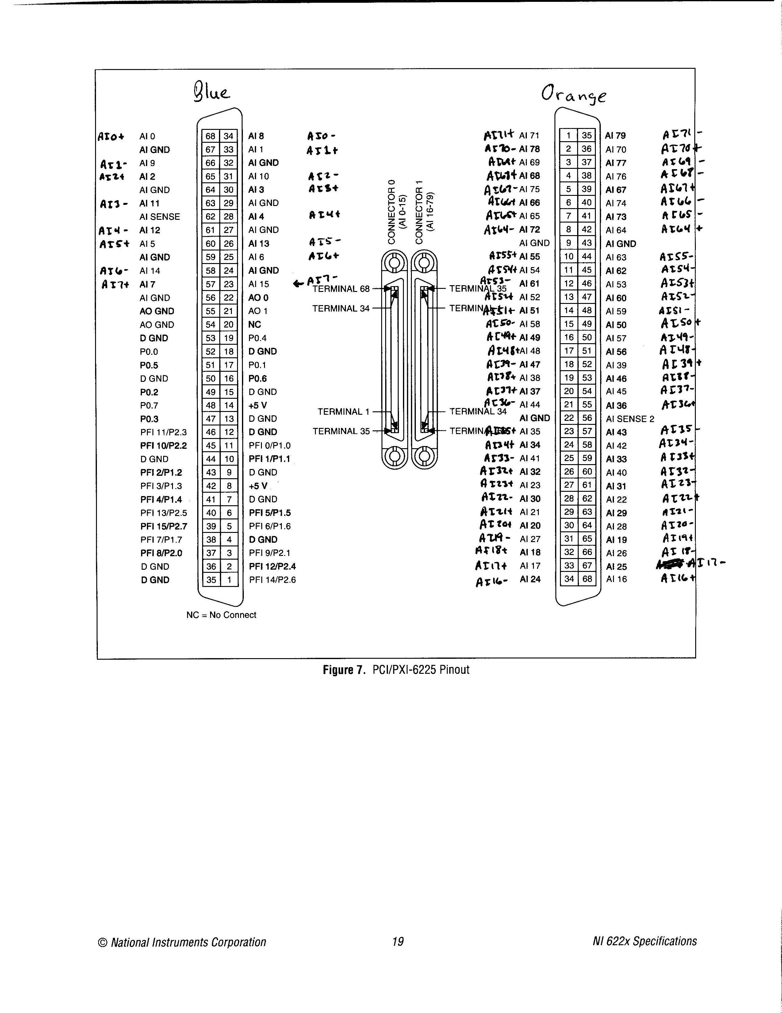
Pinout of the device from the PCI-6225 in differential Mode of I
Simple question: where is the pinout of the device for the card PCI-6225 for differential of analog input mode? I looked in the device list of the pins in MAX, in the NI 622 x specifications document and several other places, but I was not able to find it. I found the pinout for referenced asymmetrical measures, but no differential.
Related issue: most people use devices like the 6225 for no entries analog differential? So why in tarnation do many brand of material OR that upper and lower manuals, looking for the differential input version?
Thank you!
«Referring the number of pins would make it impossible to use the same code when you change maps DAQ.»
I'm not sure I followed here. Can you please explain a little further? Are you referring to the 1-68 0 connector pins and 1-68 pin connector 1? If so, I'm not sure, I followed. A different pinout may not change the code. If I had to replace a 6225 with another equivalent at least DAQmx device as many channels and the device number was the same, then I'd not change all the names of channel in the code, I? It would certainly change the wiring, which is precisely what I'm doing right now.
I know that the analog input channels look like ai0, ai1, etc.. My concern is later: where the jumps occur when you're in differential mode?
I have attached exactly what I would like to see in the documentation of ALL analog input device which allows the differential mode, only with the + and - channel names only and not the labels AI0-AI79. I couldn't find this photo any place, but rather had to laboriously calculate this pinout. If you know where to find this photo, I would be very grateful.
Thanks for the reply.
-
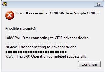
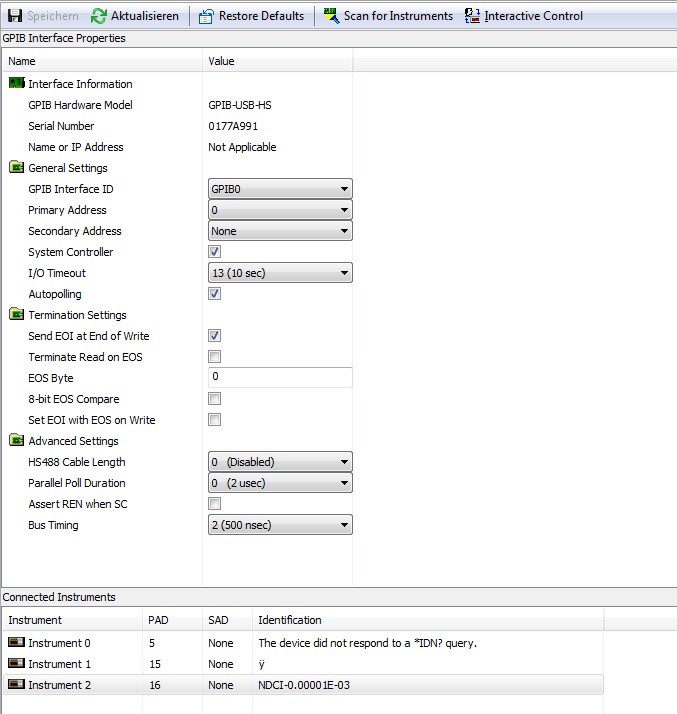
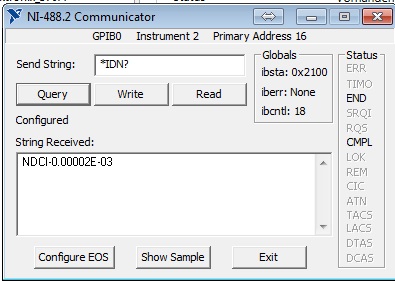
"Connection to the GPIB driver or device error".
Hi all
It is the first assignment, I do on this forum, so please be refrain, if I make mistakes.
Now my problem:
I use the NI USB2GPIB adapter and want to communicate with any GPIB device using the Simple screw GPIB.vi NOR-example.
From the VI the GPIB - correct the device address occurs an error:
My settings of the GPIB adapter are:
Anyone can unmask, why in MAX, the communication is running:
but not in VI. In the VI I get error indicator, when I try to use the function write GPIB (error bit 15 is set to 1).
Can someone help me please?
Sincere best wishes from good old Germany,
z
-
will transfer data in parallel in the GPIB interface?
Hi all
I have two devices (that support GPIB) connected in series and connect to the GPIB interface card. These two devices have two different addresses and I use VISA module to send data at the same time. GPIB cables are connected in series, so that means it will be locked during the transfer of data to a device? I think that the GPIB transfer rates are not low (about 1 MB/s), but it takes so long to transfer 500 KB to the unit (approximately 45 seconds).
-
Z400: Z400 firewire pinout of the connector?
I noticed that the connector on the front panel 1394 connector 12 pin rather than the standard 10 pin. Does anyone know the pinout? It is not in the maintenance manual. Thank you!
Here is the pinout of the Z400 J13 1394 header. Keep in mind that it is looking at the head of the motherboard, and not the connector at the end of the connector to the front panel, which could be a reflection, depending on how you look at the connector.
The best way to determine the pinout is to use the keyed/missing pins as a refrence.
-
Get the serial number of the GPIB-USB-HS
How can I get the serial number of the GPIB-USB-HS device programmatically?
I worked on it. Attached simple solution.
It is possible using the driver of VISA?
-
Slow data transfer during the reading of the GPIB (Horiba CCD 3000) device
Hello to everyone.
I'm trying to connect with a CCD camera (CCD 3000 - company Horiba (formerly Jobin Yvon)))
The connection is made on the GPIB (PCI)
The CCD device is old enough and will not support orders GPIB standard (p. ex. * IDN?)
The problem I have is that after I take a picture, when I want to read data from the CCD
It takes about 10 seconds before arrived it all the data to the computer
the delay is proportional to the size of array of pixels:
When I take the data of the entire area of the CCD (1024 * 256 pixel * 16 bits = 512kB)
It takes 10 seconds
When I consider 4 x 4 pixels 1 pixel (this is done by the hardware) (256 * 64 pixels * 16 bits = 32 k) it taks about one second
What can be the cause of this kind of problem
How can I solve it?
Thank you
As you say, the camera is quite old. Maybe 50 kB/s is the maximum data rate (probably very 56 Kbps).
-
How can I configure the GPIB Tektronix tds2024 he is detected by MAX
I try to connect the Oscilloscope Tektronix of TDS2024 to use in LabView. I use the GPIB port. I have to do something with the TDS2024? Or it should automatically detect it. I tried 2 different cables and are detected by the LabView "Measure & Automation Explorer" when connected.
Hello
All you have to do is plug your instrument, MAX throw if you have not already done so and scan for instruments.
You should see the instrument listed under the GPIB device.
Hope this helps
Concerning
Ray Farmer
-
ResetSys on the GPIB instruments with addresses
Style calls (alias calls NOR-488. 2 multi-device) IEEE 488.2 use a two-byte addressing scheme where the subaddress is in the high byte.
Help OR-488 online. 2:
"Some of the calls to several NOR-488 devices. 2 have an address or address list setting. An address is a representation of 16 bits of the address of the GPIB device. The primary address is stored in the low byte and secondary address, if any, is stored in the high byte. For example, a device to the main address 6 and secondary address 0 x 67 has address 0 x 6706. A NULL address is represented as 0xffff. An address list is represented by a list separated by commas in addresses, such as 1,2,3.So, your channel should be:
-
Writing a driver for the GPIB-ENET100 in C++ based on a Linux machine
I picked up some remains of a driver for this device and I'm trying to resurrect it for a new project.
Basic Comms between the host and the device of the GPIB-ENET work OK, I can analyze the GPIB bus for instruments and address address Analyzer connected properly.
But, if I try and write commands to the instrument I get an error GPIB.
Work of communication very well by using windows OR browser based tool, so I've captured the Ethernet traffic and found several types of messages I do not recognize. He also seems to be sending messages on port 5015, but also the main port 5000.
SO, my question: is there a document covering the interface with the device at a low level of TCP message? Alternatively, as I suspect it is the secret of stuff and I'm supposed to buy an expensive software of NOR?
SOLVED.
After connecting to the GPIB-ENET100 using ibfind and setting various options on board level it is essential to drop and reconnect the plug before attempting to connect and communicate at the peripheral level.
My version of ibfind opens a socket and my version of ibonl closes the socket when it is called to set a Board/device offline.
The driver now works perfectly.
-
NAT9914 - direct connection to the GPIB bus
Hello
I have some experience with NAT9914xx. I understand, from various sources, this ASIC is connected to the GPIB bus through a Transceiver ICs, i.e. it SN75ALS160 and SN75ALS162. While I'm waiting for the part, I wish I can perform some tests.
So here's the question: If the only devices exist on a GPIB bus is my test Board and a GPIB equipment, can I have the NAT9914 on my board test connected directly to the GPIB bus without using the transceivers?
Thanks & best regards,
Tan of WH
Hello
These transceivers are absolutely necessary to communicate with GPIB instruments. It's why they're in the hardware section of the manual 9914. Transceivers will display correct tension/line transitions. Without them, there will be errors in communication.
I hope this helps.
Steven T.

Maybe you are looking for
-
The Boot Camp Assistant problems
I'm trying to install 10 Windows on my MacBook Pro 13.3 2015 "running Mac OS X El Capitan (10.11.2) but I can't not (for software that is not supported by Mac OS X). I tried several times but it still says that my disk space is not enough (don't reme
-
Files missing after moving iMovie events from local disk to external HARD disk. Are they lost?
Hi all Tonight, I tried to clear up little space on my local HARD drive and wanted to spend my events/projects of the iMovie local library to an external HARD disk, which I connected via firewire 800. I opened iMovie (v10.1 - current version with all
-
Problem in network players and the properties of my computer...
I am facing problem to open the network drives in a system. I did the following: If I open CMD and ping on the sound database server responding and so to get the IP address of DHCP. But when you access the shared folders on the server requires: \\Ser
-
I downloaded WMP 11 but now all my music appears as words. How can I get the library appears as the covers of as if it were before? Some of the music that I downloaded a few appears as a name or a song title.
-
Cannot share my printer on VISTA Home Premium
Hello... I configured a Brother printer as a local printer on my computer VISTA Home Premiun (latest printer drivers) and you want to share with the other computer on the network running Windows XP Professional. I tried to turn on the sharing of prin