Platform in the PictureIcon sample resource
Hello
I have compiled just the Mac version of the PictureIcon sample, and I'm a bit confused about how bmp images are referenced.
The ODFRC for the widget is defined as:
PicIcoPictureWidget
(
kPicIcoCustomPictureWidgetId, / / WidgetId
kPicIcoTopOutsidePictureRsrcID,.
kPicIcoPluginID, / / RsrcId
kBindNone, / / binding framework
Frame (105, 35, 185, 85),
kTrue, kTrue, / / Visible, Enabled
/ / Custom fields
kPicIcoTopOutsidePictureRsrcID, / / toggles between these two photos
kPicIcoTopInsidePictureRsrcID, / / when the photo is clicked on
),
and the resource ID; kPicIcoTopOutsidePictureRsrcID and kPicIcoTopInsidePictureRsrcID are defined in PicIcoID.h to:
#define kPicIcoTopOutsidePictureRsrcID 101
#define kPicIcoTopInsidePictureRsrcID 102
But how are the mapped constant 101 and 102 to the bmp images?
Cordially Toke
PicIco.rc has Windows definitions.
kPicIcoTopOutsidePictureRsrcID DISCARDABLE BITMAP "TopOutside.bmp".
kPicIcoTopInsidePictureRsrcID DISCARDABLE BITMAP "TopInside.bmp".
kPicIcoBottomOutsidePictureRsrcID DISCARDABLE BITMAP "BottomOutside.bmp".
kPicIcoBottomInsidePictureRsrcID DISCARDABLE BITMAP "BottomInside.bmp".
kPicIcoCenterVertPictureRsrcID DISCARDABLE BITMAP "CenterVert.bmp".
kPicIcoCenterHorzPictureRsrcID DISCARDABLE BITMAP "CenterHorz.bmp".
kPicIcoCenterCompPictureRsrcID DISCARDABLE BITMAP "CenterComp.bmp".
Tags: InDesign
Similar Questions
-
I'm trying to go through the course of the entire sample to get an idea how to build my own. But I can't go beyond this module.
"There is a sample course in the platform called Business communication (sample course). He won't move beyond three module when I'm logged in as long as learner. »

Hello
You are looking in the settings of course. You must go to the author > library Module, select the module causing delivers and check performance criteria.
Kind regards
MILIN
-
Can I change the time sampling real Graphics Performance
I am preparing a demonstration and want to display the allocation of resources in real time using vSphere performance dashboards. Unfortunately, the default sampling rate and an average of periods are not optimal for display assignments for resources with our demonstration. Can someone tell me if there is an easy way to change these default values?
The sampling rate for the graphics in real time is 20 seconds, which is probably OK, but I WOULD change for 10 seconds. However, the main issue of concern is the number of samples in which this average is calculated. This value seems to be very high (I think I saw 300 in a document). Because this number is very high, the changes I make say every minute (for demonstration purposes), allocation bands don't really show up very well in vSphere performance dashboards. For example:
If my host has had 10 GB memory active during the last 5 minutes and my demo releases suddenly a very large part of this memory, the performance table the sudden deallocation with the last word on average 10 minutes of data and shows a gradual decline in the allocation of memory.
This behavior is probably what is desired in a system of monitoring, BUT for my demonstration, I want to show a more realistic view of the allocation of resources using vSphere performance dashboards. This could be accomplished if periods of rate, for a sample mean are configurable.
Any help is greatly appreciated.
On the other hand, I think it's that they do not change settings realtim. It's good for my purpose
I do not know the slow answer due to the memory alloc/dealloc.
BTW if you think the answer above resolved your problem, you might mark it as response.
-
create view does not work with the role of resource
I just upgraded from 10.2.0.1 to 11.1.0.7
the role of resource users could create views on the old database...
now, they can't
ORA-01031 insufficient privileges
I have to give them create it all discovers the system privileges(1) I assume you mean that you gave them the CREATE VIEW privilege. Not CREATE ANY VIEW. The latter would allow them to create a view owned by another user who would be dangerous enough.
(2) it is not related to the role of RESOURCE. It is almost certainly related to the CONNECT role. CREATE VIEW (among other privileges) has revoked the CONNECT role in point 10.2. I don't know why your 10.2 database was working, I guess that you updated from an earlier version, in which case the update may not have removed the privilege correctly (see Metalink: 317258.1).
(3) you certainly don't want to use the CONNECT role or RESOURCES in the application of the production. Were the roles of the sample which have been overloaded with privileges for the various elements of the sample code. You should really create your own roles with of whatever your users must actually rather than using these predefined roles of privileges.
Justin
-
Measurement error of the County of edge by using the external sample clock
Hello
I'm trying to measure the number of edges (rising) on a square wave at 5 kHz with a generator function on a device of the NI PCIe-6363. I configured a channel of County of front edge of counter at the entrance of the PFI8 device. I use an external sample clock that is provided by the output of the meter of a NI USB-6211 housing channel. If I acquire for 10secs then ideally I would expect to see a total of 50000 edges measured on the meter inlet channel. However, my reading is anywhere between 49900 and 50000.
When I use the internal clock of time base to measure the edges, the measure is accurate and almost always exactly 50000. I understand that when you use the external sample clock, the precision of the measurements is subject to noise level of the clock signal. However, I checked the clock signal is stable and not very noisy. Any reason why there is an error of measurement and how tolerance should I expect when using an external sample clock compared to when you use the internal time base clock?
Also, what is best clock Frequency (with respect to the frequency of the input signal) when using an external clock?
Thank you
Noblet
Hi all
Thanks for all your sugggestions. I was using an input signal with a function generator which had a range of 8V. It turns out that the reduction of the amplitude to 5V solves the problem. I was able to get accurate numbers with the 6211 external clock.
Thank you
Noblet
-
I connect serial port COM3 to a digital multimeter, I can sure that COM3 is displayed in Device Manager. but I don't know if COM3 is in the name of resource VISA list. If COM3 is not in the list, I want to update resource VISA name.
So my question is how to program can get the entire list of the name of resource VISA, so that the program can compare resource VISA with COM3 automatically name? How the program can update the name of resource VISA, if COM3 is not in the list?
LabVIEW 2011 windows 7
Thank you
Control of resources VISA automatically displays the available visa resources. If it isn't then looks like there was an error in the installation of NI-VISA.
An alternative is to use your own control, as suggested here: http://forums.ni.com/t5/LabVIEW/VISA-resource-name-control-want-to-refresh-list-of-COM-ports/td-p/13...
-
divide the internal sample clock (VCXO)
Hi all
I want to divide clock source internal sample of my high-speed 5122 digitizer PXI card.
5122 PXI, 200 MHz internal clcok source example. I want to taste my data at 10 MHz.
So I want to divide down the clock of internal sampling by a factor of 20.
I want to do it programmatically.
I have found no vi node or property for that (although found the node property for entry divider OR worn... but which has been used only for reference for on-board clock clock)
Help me as soon as possible...
Hi Jirav,
I just wanted to clear some things. The 5122 has a sampling rate 100 MECH's maximum real-time. / s (not 200 MHz as you originally suggested). To obtain a rate of 10 MHz, you would be divided down by a factor of 10. From page 13 of the document specifications NI 5122:
Just to add to what Henrik suggested, the following help topic describes the specific VI to configure horizontal properties such as the sampling frequency, he mentioned:
http://zone.NI.com/reference/en-XX/help/370592P-01/scopeviref/niscope_configure_horizontal_timing/
Most of the expedition OR SCOPE examples use the VI above and there is an entry for "min sampling rate" where you can simply specify the value "10 M" or '10000000' to get the device of sampling at a lower rate.
Note: because the digitizer allows only sampling frequencies which are an integer divide down the maximum sampling frequency, rate will always be forced to match up to the second tier legal sample. For example, if you specify '9.8435 M', it would automatically force the rate up to 10 MHz. To display the actual value that the scanner is used, you can query the property node "Actual sampling frequency" at any point in your code after the configurations have been committed digitizer. The help manual describes this property on the following page:
http://zone.NI.com/reference/en-XX/help/370592N-01/scopepropref/pniscope_actualsamplerate/
Kind regards
-
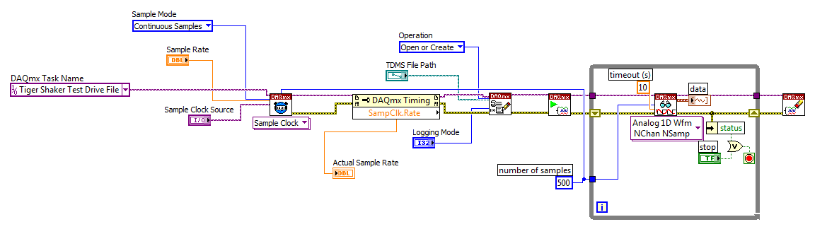
How to change the DAQmx sampling frequency
Hello
I'm trying to: record streaming channels (acceleration 21 and 1 tension) using a DAQmx task, then convert the data to a PDM file. The program files and output to the TDMS file very well. The issue I'm having is that I can't change the sampling frequency. I want to record 500samples/s and I can not get the "real sampling rate" of change of 1651.61samples / s. I am trying to use the clock to do this and I succumbed. I also tried to change the settings of "Timing" in the task without a bit of luck. Here is a screenshot of the .VI I created. I've also attached a copy of the file VI. Any help would be greatly appreciated!
Thank you
Tony
You will need to provide the model of your device. You can also look in the sheet/manual to see what the real supported sampling rates. Some devices have limited rates.
-
DaqMX wait the next sample causing slow down Clock.vi
Hello
I have a question about the proper use of DaqMX wait for next sample clock.
I read channels analog voltage on a map or pcie-6259.
I would like to read as soon as possible make your comments between each of these points of single data points.
I wish I had an error generated if I miss a data point.
From reading the forums, I've gathered that the best way to do it is using the Timed Single Point material.
A simplified program that I use to test this is attached.
If I remove the DaqMX wait for next sample Clock.vi, my program seems to work.
I added a counter to check the total time is as expected.
For example, the program seems to work at the speed appropriate for 120.
However, without that vi, it seems that the program does not generate a warning if I missed a sample.
So I thought that the next sample clock waiting vi could be used to determine if a single data point has been missed using the output "is late."
However, when I add inside as shown in the joint, the program seems to slow down considerably.
At high rates as 120000, I get the error:-209802
14kHz is the approximate maximum rate before you start to make mistakes.
My question is: is this the right way to check a missed sample? I don't understand why the wait next sample Clock.vi is originally a slow down. Without this vi, the program does just what I want except that I do not have strict error control.
My confusion may be based on a lack of understanding of real-time systems. I don't think I do 'real time' as I run on an ordinary pc, so maybe I use some features that I wouldn't.
Thank you
Mike
Mike,
You should be able to read to return delays errors and warnings by setting the DAQmx real-time-> ReportMissedSamp property. I think that if you enable this, you will see errors or warnings (according to the DAQmx real-time-> ConvertLateErrorsToWarnings) in the case where you use read-only. I'm a little surprised that you have measured your application works at 120 kHz without waiting for next sample clock (WFNSC), although I'm not surprised that it would be significantly faster. I think if you call read-only, you'll read the last sample available regardless of whether you would of missed samples or not. When you call WFNSC, DAQmx will always wait for the next, if you are late or not sample clock. In this case, you will wait an additional sample clock that is not the case in read-only. Once again, I expect that, in both cases, your loop would not go to 120 kHz.
Features real-time DAQmx (hardware Timed Single Point - HWTSP) are a set of features that are optimized for a one-time operation, but also a mechanism to provide feedback as to if a request is following the acquisition. There is nothing inherently wrong with using this feature on a non real-time OS. However, planner of a non real-time OS is not going to be deterministic. This means that your app 'real time' may be interrupted for a period not confined while the BONE died in the service of other applications or everything he needs to do. DAQmx will always tell you if your application is to follow, but can do nothing to guarantee that this will happen. Thus, your request * must * tolerant bet of this type of interruption.
There are a few things to consider. If it is important that you perform the action at a given rate, then you should consider using a real-time operating system, or even with an FPGA based approach. If it is not essential to your system, you might consider using is HWTSP, where you do not declare lack samples (DAQmx simply give you the most recent example), or you could avoid HW timing all together and just use HAVE request to acquire a sample at a time. What is appropriate depends on the requirements of your application.
Hope that helps,
Dan
-
Distortion of the signal caused by the channels # sampled and sampling frequency
I am using an acquisition of data USB-6211 (250 ksps / s) and looking at the sample channels 3s 80kS. (Labview 2012)
When I taste one channel, it looks fine (1 Channel_Sampled First_250kS), but when I add another channel to be sampled, the signal is driven down and that it depends on which channel is sampled (2 channels (Different) _Sampled First_40kS and 2 Channels_Sampled First_30kS). Addition of channel 3, it pulls down even more. I also noticed that the sampling rate also distorts the signal the higher the sampling rate, the more the signal is driven down.
The acquisition of data IS sampling of signals "correctly" when I run my Labview VI my external hardware begins to read in correctly based on the distortion of the signal.
What is the cause and is there a way to fix this?
I have attached the waveform above captures and can post some if necessary.
Thanks in advance,
WBrenneman
That's exactly what ghosts means. The measurement signals later is affected by other signals. It happens usually if you have a high impedance input signal. Adding pads like you can help solve this problem by making the signal to a lower impedance.
Ghosting would probably look worse to the frequency sampling rates higher, just as you said that you had problems, as it provides less time between samples of the amplifier set new voltage level when the multiplexer allows to switch between input signals.
-
Can not find the name of resource VISA
I am trying to run the example code, provided by the manufacturer with a 3a Keithley 2420 SourceMeter. It is turned on and put in place for 488,1 protocol GPIB. It is connected to my computer via a GPIB KUSB - 488A cable. On the front panel of the example program, there is a menu drop down titled "VISA resource name." The two options at my disposal are LPT1 and COM1, but I don't think one of this is the name of the resource on the right. Does anyone know what the name of resource VISA should I use with the Keithley, or how I can find this? If it helps, I have provided the example program I use. Thanks in advance!
As a general rule, only the material NOR will be recognized in MAX and you wouldn't get any VISA resource for Auditors not - NOR. If there is a VISA for the Keithley driver, you can try to install as secondary visa driver and enable Tulip MAX. Keithley support support is the best place to ask questions about the installation of their hardware to LabVIEW.
-
By dividing the time base clock sample by N, we're the first sample on pulse 1 or pulse N?
I use an external source for the time base a task of analog input sample clock. I'm dividing down by 100 to get my sample clock. Is could someone please tell me if my first sample clock pulse will be generated on the first impulse of the source of the base of external time, or about the 100th?
I use a M Series device, but can't see a time diagram in the manual that answers my question.
Thank you.
CASE NO.
CERTIFICATION AUTHORITIES,
I don't think it's possible to use the sample clock of 3 kHz on the fast map as the time base clock sample on the slow map and get the first sample to align. The fast card can enjoy on each pulse signal 3 kHz, while the slow card will have to meet the requirement of the initial delay before he can deliver a sample clock. If you turn this initial delay a minimum of two ticks of the time base, the slow card eventually picking around the edges of the clock 2, 102, 202, etc.. You can set the initial delay for 100, which means that the slow card would taste on the edges, 100, 200, 300... but you wouldn't get a card reading slow on the first edge of your sample clock.
Hope that helps,
Dan
-
Save the high sampling rate data
Hello!
I use NI PXI-4462. (204.8kS, input analog 4 / s sampling frequency)
I want to collect data from "load" (channel 1) and "acceleration sensor" (2nd, 3rd, 4th channel).
I also want to save data to a text file.
So I do a front pannel and block diagram. You can see in the attached file.
The program works well in a low sampling rate.
However, when I put up to 204800 s/s sample rate, the program gives me "error-200279".»
I don't know what means this error, and I know why this happened in the high sampling rate.
I want to know how I can fix it.
Is there any problem in my diagram?
Is it possible to save high sampling rate data?
I really want to samplling more than 200000 s/s rate.
I would appreciate if you can help me.
Thank you.
NH,
You have provided excellent documentation. So what has happened is that the amount of time it takes to run the other portion of the loop results in a number of samples to be taken is greater than the size of the buffer you provided (I don't know exactly what it is, but it will happen at high frequencies of sampling high) resulting in samples are crushed. You might be best served in this case to take a loop of producer-consumer - have the loop you have acquire the data but then have an additional loop that processes the data in parallel with the acquisition. The data would be shipped from the producer to the consumer via a queue. However, a caveat is that, if you have a queue that is infinitely deep and you start to fall behind, you will find at the sampling frequency, you specify that you will begin to use more and more memory. In this case, you will need to find a way to optimise your calculations or allow acquisition with loss.
I hope this helps. Matt
-
Effectively change the continuous sample mode sample mode finished
9188 chassis, modules (HAVE them), 9 of Labview
I want to acquire continually (and display) given at a fast rate to date, and then when a 'trigger arms' State is detected, the switch to finished hardware, triggered task with pre-trigger samples with a minimum loss of perceived as update rate.
What is the best way to do
Thank you
Collin
I started my answer a long time ago while waiting for a reboot and am just finally getting back to it. I see that you got another another answer in the meantime. On the outbreak of reference, here is another link that might help some: Acq suite w / Ref Trig
I did have not tinkered with reference trigger a lot, so not sure what is meant in the link above about the task being an acquisition over 'the end'. Maybe the task continues to fill the buffer just before there about to overwrite the first sample of pre-trigger?
In any case, my original thought the whole thing was on another track. If the trigger Ref works for you, it'll be easier. But if Ref trigger causes the acquisition of stop * and * you really need to keep it going permanently, then consider the things below:
-------------------------------------------------------------------------------------------
Passage of the continuous sampling done will require the judgment and the reprogramming of your task, and you will have a 'blind spot' of data loss, while what is happening.
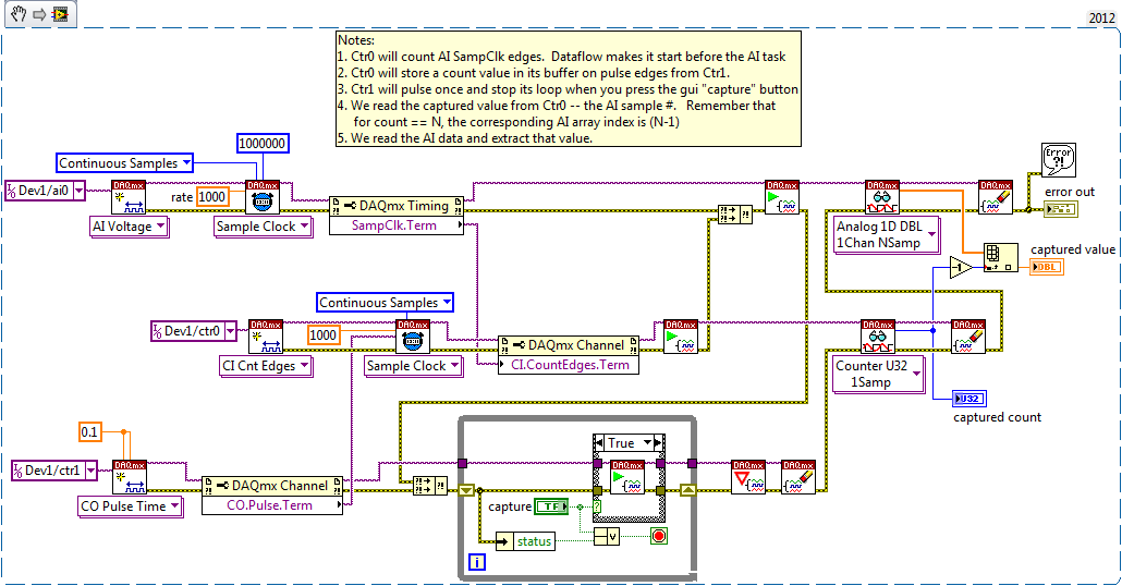
An approach that I think is to stick to a sampling WAS continuous, but also set up a counter task that can count it HAVE examples of clock and capture on the trigger signal. The captured value of count will be HAVE it taste # when the trigger has occurred, and then easily post-process you your data HAVE to find the subset that represents your data before and after the desired trigger.
Here is an excerpt of what I mean 2012:
-Kevin P
-
Some or all of the requested samples are not yet acquired: API change responsible?
My Delphi program, which works very well under NOR-DAQmx 8.9.0f4 on a set of material, fails under 9.0.0f2 on what I received insurance material is equivalent. The error is «some or all of the requested samples are not yet acquired...» ». This happens even to slow scanning rates, and coming to suspect that the API has changed subtly in the transition from version 8 to 9. What is the probability is it? Now that I have access to the source code on the new hardware (NI PXI-1044 with computer integrated PXI-8110) is there something I can do to check this?
Hi Francis,.
Your program still calls DAQmxCfgDigEdgeStartTrig() for all the tasks of the slave? If you do not do this, the devices are beginning to acquire data at the same time, and since you pass 0 for the timeout parameter to DAQmxReadBinaryI16(), out-of-sync devices could certainly time-out errors.
In addition, you must ensure you start the slave devices before the master device, so that they're already waiting for a trigger at the start of the master device.
Brad


Maybe you are looking for
-
Satellite U400-17Y - Bluetooth does not work after upgrade to win 10
Hello I have improved my Windows7 laptop at 10 now. While upgrading to windows 10 he messaged device RFCOMM Bluetooth may not work with Windows 10. So now, my laptop Bluetooth not working do not. Opening of Bluetooth, it shows "Error-ECCentre-1.exe -
-
Satellite Pro L300 - CD/DVD does not appear on my computer
Hello! This is probably a silly question / easy but I am very new in this and... my CD/DVD unit does not work.It does not show on 'my computer' and when I insert a disc, nothing happens (with the exception of a humming noise but then nothing)... Plea
-
Error message 1802 on the installation of the Wireless Broadcom Minipci card
-
The update of window tried to 4 updates. Some were installed some has failed. Here are the ones failed.Update for Microsoft Office Outlook Junk Email Filter (KB975960)Update for Microsoft Word 2007 (KB974561)A security update for the 2007 Microsoft
-
Help the DV4285EA BIOS password
Hello, I tried to access my BIOS on this laptop, but it seems that there is a password. After 3 errors it displays "system disabled 05803." You kindly tell me the password of the BIOS? Thank you.