PowerVault md interchangeability of controller chassis.
Hi, md3000i md3000 the md1000 and all use the same chassis and backplane? We know that backplane on md storage arrays are an SPF. As spare parts for our md3000i, backplane failure, I could just keep a chassis md1000 autour and if I lose backplane on the 3000i that I could just pull on the 3000i controllers and put them in the spare wheel 1000 and I be ready to go? If someone did it or clear it please reply. Thanks in advance. M
It would work, but what you have to do, is make a syswipe that the controllers are a different interface. Once you do the syswipe and install the new controllers and setup of the table, it should work. By doing this it would not be supported if you were to put in support because she would not correspond to the original configuration.
Tags: Dell Products
Similar Questions
-
Vs (standalone chassis and controller) chassis
main difference b/w the chassis and independent chassis and controller , for example
and
What is the best?
The 9138 is a standalone chassis, running Windows or OTR.
The 9178 is just a chassis holding your Modules of e. You must have a computer connected to make measurements.
And questions what is the best, can only be answered if we know your needs.
In any case, I would recommend to contact your local office of NOR and speak with a technical sales representative.
Christian
-
1042 q with PXI 8360-controller and maps of Pickering
Hello
I have a 1042 q with a PXI-8360 controller chassis and some maps of Pickering.
Connected to the XP - PC with a PCI-e-card-
Installed is only neither Max nor-PXI, Ni-Visa...
Now the question is how to set up the chassis in the 4.7 or max?
In Max, I see a line with PXI system (unidentified) under "Geräte und interfaces". I tried to load some of the deliverered ini with pxi OR cd files, but I can't control anything.
Can someone me a gibe hint what to do?
I have doenloaded a pickering Web site pipx40vpp.zp file which should cover all my map of pickering a has also a few frontpanles.
But at the start of the frontpanels it says "no card detected". I think I must first of all put in correct place in the max.
Thanks for any help
Thank you very much for the help.
Problem is now solved:
The main problem was that the PCIx1 slot is not working. I put the card in an another PCIx slot and then he worked at the same time.
I found this trick here:
http://digital.NI.com/public.nsf/allkb/05B7131814A5DDA38625710F006BB098?OpenDocument
Try different PCI or PCI Express locations in the host PC for you MXI interface.
The algorithm that use certain BIOS has best behavior in certain time slots than others.Maybe someone will need it in the future.
-
PowerVault MD1000 Perc 6/E hot swap
Which would prevent me from doing a Hot Swap on a 136GB 15K SAS drive on a PowerVault MD1000 with a Controller PERC 6/E for Adaptive Read Ahead, write new policy, broadband strategy of disk, RAID-10 in degraded state, a defective disk cache 64 KB, disabled?
Blew up a car and you want to make sure I can hot swap on this machine. I read through product docs, but you are looking for something extra that I want to check that I missed on. Server of our warranty and support from last year. Everything I see is green lighted to go, but I always want to get will as many resources as possible before blowing a RAID 10 potentially because a controller had some setting that prevents a switchable good hot to rebuild. Make backups before swap, swap during off-peak hours doing rebuild starts on commercial operations.
I read through docs:
http://public.support.Unisys.com/pcproducts/ESX/docs/DellDocs5.4/en/Perc6i_6e/chapterb.htm
http://support.Dell.com/support/eDOCS/systems/MD1000/en/Hom/om_en.PDF
Hello matt.newman,
For the MD1000, you can replace a failed during execution of the MD1000 drive. When you insert the replacement drive, it will start a reconstruction.
To replace the Perc6 you will need to do is the following:
- Make sure you have a good backup tested all the MD data
- Turn off the server and the MD
- The PERC6. Remove and replace
- Turn on the MD & wait that he move to a ready state
- Turn the server & go in the new Bios Perc6 / configuration
- You have to re-create the raid10 & together for Adaptive Read Ahead, political writing back, broadband 64 KB, off the disk cache strategy
- Once you have created the raid then leave the PERC6 configuration utility and the Server post to the operating system
- Once logged on the operating system you can then run the restore to restore your data to the MD
Please let us know if you have any other questions.
-
Dischetto pilot controllo Sata Powervault NF100 [MS]
Salvo..., x motivi di perdita file, dobbiamo reinstallare he operating system
Windows storage server 2003 r2 x 64, sul powervault NF100 con con controller raid due hd sata...
Durante sommergibili del only operating system F6 x creare i personal raid, disk x raid driver controllo, disco for mi asks he dove posso scaricarli?
Grazie
Salve,
dopo aver premuto S e caricato pilot del sas5 prema per, alla schermata buttons it system information:
the installer will take care for the mass following storage device:
con indicated it modello di controller
to basso sulla legenda e indicated:
Additional feature S specify - ENTER continue - out F3
quindi prema ENTER per andare avanti.
Speaking saluti
Manual
-
OCXO-SMU-6674 t PXI_CLK10_In questions
Hello
Currently I have a SMU-1082, SMU-8101 controller chassis and an SMU-6674 t timing card installed in slot 4. What I want to do is connect the oscillator on the timing card to clk10_in to improve the accuracy of the 10 MHz reference clock.
So, here's the strange thing, mostly when I run my labview program he fails to connect saying "PXI_Clk10_In is available as a terminal only for devices in a synchronization of the destination system slot. Place your unit in a timing system slot. "and will give you the code of error-1074118597. When it breaks down I try to run the code sample to connect to PXI_Clk10_In and using MAX and it will give me the same error, but from time to time, it will work without a single error.
Whenever I turn on the frame the first thing we do is check to see if I can connect the clock, and if I can it give no problem, but if I can't do it seems that nothing I will fix it and it will remain for a period extending over several weeks to a few months. When it works, the longest, it lasted a week.
I was wondering if someone runs into something like this before, or has any suggestions on how to make it work on a regular basis?
Also if I connect to PXI_Clk10_In or not, I am able to divide the DDS and it output ClkOut so it isn't a complete failure of the module comes from the ability to connect to Clk10_In.
Just to be sure, you can try to install the patch OR-Sync 3.4.1. This hotfix provides a picture of firmware updated for the SMU-6674 t. For more information on the fix, click the link below:
Module synchronization SMU-6674 t unexpected behaviorKind regards
-Tyler
-
Adding personality to VeriStand FPGA
Hello
I am trying to add a personalized my VeriStand configuration FPGA. I use PXI-7853R in 1044 with PXI-8110 controller chassis.
The FPGA model itself is running properly and the fpgaconfig file is modified. The fpgaconfig and the bitfile are added to the propper directory. Now when I want to add it as a target FPGA, I get the following error:
***********************************
LabVIEW: File not found. The file could be
moved or deleted, or the path may be incorrectly formatted for the
Operating system. For example, use- as Windows path separators: on Mac OS
X, and on Linux. Check that the path is by using the command prompt or
File Explorer.=========================
NOR-488: The non-existent GPIB interface.
C:\Documents
and All Users\Documents\National Instruments\NI VeriStand
2010\FPGA\PXI-7853R HighSpeed Interfaces.lvbitx***********************************
I checked
but the http://Digital.ni.com/public.nsf/allkb/2FA525A8585A92E9862566EE002A3755 was not able to address the issue.
I enclose a few screenshots to give an image of my installation.
p.s. I'm not planning to use the GPIB.
Error 7 is a generic "file not found" error in LabVIEW. Unfortunately, I think the NOR-488 driver also uses the error code 7 for a GPIB interface to the nonexeistent, and the error description lists all possible sources. In your case, the error is due to a missing file and has nothing to do with the GPIB.
I re - check the bitfile name in the .fpgaconfig and verify that it is the path listed:
C:\Documents
and All Users\Documents\National Instruments\NI VeriStand
2010\FPGA\PXI-7853R HighSpeed Interfaces.lvbitxIf you can get the files .fpgaconfig and .lvbitx, we try here and I hope that give you the best guidance.
-
all samples n transferred from the buffer
Hi all
I have a question for every N samples transferred DAQmx event buffer. By looking at the description and the very limited DevZones and KBs on this one, I am inclined to believe that the name is perfectly descriptive of what must be his behavior (i.e. all samples N transferred from the PC buffer in the DAQmx FIFO, it should report an event). However, when I put it into practice in an example, either I have something misconfigured (wouldn't be the first time) or I have a basic misunderstanding of the event itself or how DAQmx puts in buffer work with regeneration (certainly wouldn't be the first time).
In my example, I went out 10 samples from k to 1 k rate - so 10 seconds of data. I recorded for every N samples transferred from the event of the buffer with a 2000 sampleInterval. I changed my status of application of transfer of data within the embedded memory in full with the hope that it will permanently fill my buffer with samples regenerated (from this link ). My hope would be that after 2000 samples had been taken out by the device (e.g., take the 2 seconds) 2000 fewer items in the DMA FIFO, it would have yielded 2000 samples of the PC for the FIFO DMA buffer and so the event fires. In practice it is... not to do so. I have a counter on the event that shows it fires once 752 almost immediately, then lights up regularly after that in spurts of 4 or 5. I am at a loss.
Could someone please shed some light on this for me - both on my misunderstanding of what I'm supposed to be to see if this is the case and also explain why I see what I see now?
LV 2013 (32 bit)
9.8.0f3 DAQmx
Network of the cDAQ chassis: 9184
cDAQ module: 9264Thank you
There is a large (unspecced, but the order of several MB) buffer on the 9184. He came several times on the forum, here a link to an another discussion about this. Quote me:
Unfortunately, I don't know the size of this buffer on the 9184 on the top of my head and I don't think it's in the specifications (the buffer is also shared between multiple tasks). This is not the same as the sample of 127 by buffer slot AO which is present on all chassis cDAQ - controller chassis ethernet / wireless contains an additional buffer which is not really appropriate I can say in published specifications (apparently it's 12 MB on the cDAQ wireless chassis).
The large number of events that are triggered when you start the task is the buffer is filled at startup (if the on-board buffer is almost full, the driver will send more data — you end up with several periods of your waveform output in the built-in buffer memory). So in your case, 752 events * 2000 samples/event * 2 bytes per sample = ~ 3 MB of buffer memory allocated to your task AO. I guess that sounds reasonable (again would really a spec or KB of...) I don't know how the size of the buffer is selected).
The grouping of events is due to data sent in packages to improve efficiency because there is above with each transfer.
The large buffer and the consolidation of the data are used optimizations by NOR to improve flow continuously, but can have some strange side effects as you saw. I might have a few suggestions if you describe what it is you need to do.
Best regards
-
Can you have SMU 1062 q turn on without using the power button
I use a q SMU-1062 for a test project that will take place inside a protective case. The power button on the chassis will be covered by a plate on the protective case that make it boring and difficult to switch on using the power button on the chassis. The chassis will be plugged into a power strip of travel - lite which is mounted in the case. Is it possible that I can have the power to frame on when I turn on the power strip?
I found another route. In the controller BIOS, I changed the parameters of loss of AC power to TURN on after that AC is returned. This allows me to use the power strip in my configuration to control the electric network distributed to the controller. The following steps will describe how I got this.
- Power of the SMU-8115 controller.
- A message will appear on your screen, press
to enter SETUP - Select 'Remove' (quickly, because you don't have a lot of time before the window disappears and the controller continues to load normally.)
- This will open the main Menu of the BIOS
- Select the Advanced tab (use the arrow keys to highlight the selections and the different tabs, select a setting change with 'enter'
- Select > Configuration power and rest
- Change the configuration to power on when power is restored.
The controller can be normally close by using the start menu, and "shut down".
Start button / stop of the chassis is still capable of turning the power on to the controller, but now when I shut off the AC power strip and then return power, get the controller chassis.
-
Installation of drivers required on the device target
Hi, I'm sure I used to know the answer to this, but I paint a white.
What is the best way to install the software/drivers required on a target computer (which isn't the PC that I have developed on)? Am I right in saying that if I build a Setup program for my application, this should automatically include the necessary drivers? If so, should I install before or after adding the SMU cards to the controller chassis?
Thank you
Well Yes, the installer is the way to go. You can include additional installers to include in the installation package. You can also include MAX configurations with installation for if you have defined tasks for information to this unit.
I suggest you to install the cards first, although I don't know if that makes a difference.
-
Compact Daq or Rio measurement signal and datalog
Hello
I'm in a project to create a diagnostic for an offshore wind turbine generator system.
So I have to choose a material acquisition and make the basic operations with the measured signals.
The equipment has to work without being connected to a PC, write the data in the internal memory, and then send it via ethernet.
The CDaq and the controller chassis is cheaper than CRio, but she would work without a PC (with the exception of couse the stand-alone version that is overpriced)? Is it possible to add memory via USB to a CDaq (for datalog)?
Hello
If cDAQ standalone chassis is more than your budget, then cRIO is the right/only way to go. The good thing is that they share the modules C-series real connectivity and conditioning of signals is the same. Youneedtohavesomeformoflocalintelligence/processingpowertoevenperform the taskofwritingdatatoaflashdrive "simple."
This is a technical presentation online that might interest you: measures and monitoring in Offshore Applications
Let me know if you want me to make a connection with your local technician to NEITHER.
-
Custom control with couple or the input voltage system
Hello
I'm relatively new to LabVIEW and this is the first time that I'll use for an application of movement. I have a controller/chassis cRIO-9074 with a few modules NI 9514 IO, servo motors and drives, and I'm trying to do is to use a custom control in my system (a sliding mode control law) to generate the signal for the movement of the engines. I was able to produce a movement OR softmotion but so far I've been able to produce with position, speed and acceleration as inputs and to optimize PID gains. What I want to do is to send commands to torque or tension from the entrance of my right to command control is torque for motors. What I was wondering is if it's possible with the components that I use now and if someone could direct me to useful articles or books that can help me.
Sorry if is a noobie question but I only worked theoretically with systems of control far and I didn't simulate the results with matlab before that. It is the first time that I had to get the experimental results to validate my proposed control right. Thanks in advance.
Hi,.
This may be possible, but since sending the commands of torque or tension directly don't are not supported in scan mode, you can use your 9514 FPGA mode.
This link describes the components needed to run the FPGA device.
You should be able to find examples in the Finder for example NEITHER, but here is an overview of the use of FPGA that can be useful as well.
-
Hello
I am a new mechanical engineer on FPGA and LabVIEW Real-time. I was trying to connect a sensor accelerometer for the NI 9215 Module of the 'C' series in the controller chassis 9024 cRIO but lives a hard time to find the right connections, especially with the 'GROUND '. I would appreciate a lot any effort giving me more insight on the problem that I am known and help me acquire a voltage signal. I went through various white papers, but none of them explained in detail.
Hi KarthikSrinva,
What you have described might work, but don't forget that the 9215 has a maximum range of +/-10V of its own reference to the ground (COM).
Because the battery is a floating (unreferenced) voltage source, you'll want to fill them HAVE - COM (common ground) terminals and to ensure that you have a common reference and the differential signal is not float out of reach of data acquisition. What is described in Chapter 3 of the guide to wiring field and noise considerations I think you were talking about earlier:
Wiring and considerations of noise for analog signals
http://www.NI.com/white-paper/3344/en/#toc3
Kind regards
-
Variables of engine I/O for the NI 9144 scan
I think replace a cRIO-9074 with a 9144 expansion chassis and want to make sure that the interface I have
used to access I/O variables programmatically in URL still works with the 9144. Could someone if possible
disclose the URL format?
Mike,
Here's some URL for example for channels on a 9144 expansion chassis. I used all of the default names for the EtherCAT master controller, chassis, modules and channels.
CompactRIO Target\EtherCAT Master\Device\Mod1\AI0 \\RT
CompactRIO Target\EtherCAT Master\Device\Mod2\DIO0 \\RT
CompactRIO Target\EtherCAT Master\Device2\Mod1\AI0 \\RT
PXI Target\EtherCAT Master\Device\Mod2\DIO0 \\RT
Name of the target RT RT CompactRIO target.
EtherCAT Master - name of the EtherCAT interface on the target of RT
Device: name of the 9144 chassis
Mod1 - name of the module
AI0 - the channel name
To access the 9144 chassis you must physically connect to a CompactRIO controller with two Ethernet ports or a PXI RT controller with two Ethernet ports.
-
Hello
This question is too generic. What to know exactly?
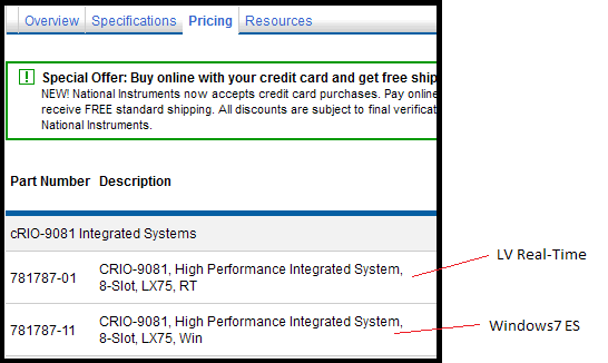
cRIO-9081, 9082 high performance controller + chassi and can be used with WES7 (not in real time) or LV Real - Time OS. The material can be used with any of these options (not both at the same time) depending on what type of application you are think.
http://sine.NI.com/NIPs/CDs/view/p/lang/en/NID/210000
Maybe you are looking for
-
How can I set English as a language whose Thunderbird works (not Czech)?
I reinstalled my Thunderbird but the new version automatically the whole environment in Czech language. How can I change it back to English?
-
I have adapters and converter of power for international travel. I was told by someone who often visits that the converter is not necessary for apple products. I don't want to ruin my phone or watch - can I use my power converter?
-
How can I add the ISO 8601 calendar to my iphone 6?
The current Gregorian calendar was a week week numbers. This should be the week 7 for the ISO 8601 rule requires a Thursday must be included in the first week, but he is listed as week 8.
-
do you need a power supply to the current entry with data acquisition or 9265
Hello I just receive the NI 9265 Daq for research in my lab. I'm trying to present entry and display it on an oscilloscope. I don't get anything. I did some research on the internet, so my question is do you need a power supply to the current entry w
-
On "Error5" by sending an excel file saved
Hi, guys I encountered a problem in my vi - save test data to an excel file and then send the file. The question is when the highest level VI runs once, the program is correct, but when I use a while loop and VI tracks the second time, it will displa