Digital magnification of output using USB-6211
Hello
I'm trying to use the example of LV "Cont writing dig port - Int clk.vi" to generate a model.
But I get the error-200077 on the sample clock. The popup error message suggests
using "we demand", but it doesn't have the choice with the DAQmx.
Any clue? Thank you.
It is correct. USB-6211 case doesn't have a digital time - analog base only. That's why the (63xx) X series cards are supported only for this example.
Tags: NI Hardware
Similar Questions
-
Strange analog output of USB-6211
I just got USB-6211 to replace USB-6001 to set the clock to external sampling on analog output for LED lighting control. The part of external clock example works fine, but the analog output voltage is strange. To do self-monitoring, I connected control pin LED to AO0 & AI0 of surveillance in the NI MAX test panel and LED control on the ground at AO - GND & GND HAVE since I have both USB-6001 and USB-6211, I conducted tests on two of them with the same setting of wire. When I generate sine wave - 5V to 5V to AO0 (from NI MAX test panel), USB-6001 can monitor the same signal AI0, but watch USB-6211 - 3, 4V to 3.4V voltage truncated. I did the test separately (wiring one device at a time), so there is no interference between the two devices. USB-6211 past self-calibration and self-monitoring. Also, I did reset devices. I don't know why they would behave differently with the same configuration, and I hope that someone could help with this question. Thank you.
Hi skuo1008,
The USB-6001 can support + / 5 output current my from terminals to analog output, while the USB-6211 box can provide only +/-2 my current output. It is likely that the load impedance is too low, causing the 6211 to hit its current compliance and thus cut the tension. If you try to exchange your load with a resistance of at least 5 v/.002A = 2500 Ohms, you should be able to see the full +/-5V sine wave. I suspect that your DUT has a words 3.4V/.002A = 1700 Ohms impedance. You could use a device with higher output current or use a more current source buffer circuit. If you do not need a bipolar output, you might also consider using digital lines to control the LEDs.
Kind regards
-
Outputs analog USB-6211 won't go below 3.375V
I use a 6211 to pulse output 0 - 5V outputs analog using an external clock as a trigger, and after successfully using the system for a while I finished with a question where none of the channels AO out lower voltages at 3.375V. My current theory is that I can have exceeded the current 2mA max output, but I don't know how, which would result in what seems to be a permanent tension.
I have reset the device and tried using other computers, but the problem remains. I ran the diagnostic utility and it fails part AO when it tries to output 0V and reads the 3V but he gave no further information. All other parts of the diagnosis are very good.
Any help would be appreciated, I'm a little stuck on my diagnosis.
Hi Airgunner1,
I'm not quite sure because I've never worked this side of the process, but if you call in they should be able to tell what your options are. Sorry I can't be more helpful!
-
How to generate a square wave of continuous digital output using USB 6343?
I need to generate a square of 600 kHz from my 6343 wave. The specifications indicate I could use PINS P2.0, but I get an error saying that it is not supported.
Thanks in advance for your help.
Jodi
Dan,
Thank you very much. Counter method worked very well.
Jodi
-
How to generate pulses on the digital i/o lines? USB-6211 labview 8.5
I want to generate a 5ms pulse on one of the lines of digital output that will be more used to delay the acquisition, DAQ.
Thank you
You will need to use counters to generate a digital pulse. I ask you to take a look in the examples that come with the DAQmx driver (in LabVIEW, help goto-> find examples). You can look for impulses and select generate Dig Pulse.vi. If you have questions, after return!
-
Current limit for analog output on USB-6211-OEM
The current output drive listed in the specifications of this card is of +/-2 my. What happens when you try to go beyond that? Is there damage to the card or is it simply rail out around 2mA. For example, if I connect a 1000 ohm load. I'm okay, if I have the output up to 2V (= 2mA), but what happens when I exit 3V with the same 1000 ohm load?
Thank you.
Protection of the overdrive is 2.4 mA, which means that you can ride this current without damaging the card, but a current of approximately 2 mA, tension is more guaranteed to be compliant to the specifications.
Kind regards
Brian P
-
OR USB-6211 is used to count climbing on board TTL
Hello
I'm new to NOR-DAQ cards, and so before buying whatever it is would like to know if it is possible to use a device, NI USB-6211
County and bin amounting to edges of a TTL signal.
What I want to do is to count how many rising edges of a TTL signal I get in a period of 1 ms; a 20 Mhz sampling frequency should be fine.
I would like to use Matlab to control and read the number of edges that are counted as well as in the meantime write and read digital IO ports from the USB-6211.
Is it maybe possible to leave the external TTL signal trigger a 6211 counters, an output then periodically (1 ms) and reset the value of the counter?
Is it possible and if yes, is it a good idea?
Thanks and regards,
Manual
Manual Hi
In order to generate this signal, I could use a second timer mode continuous pulse Train generation, right?
-> Right. You can choose between 2 options
(1) get the signal to another device, for example signal generator or something like that. If you cannot use such a device, you must select the second solution->
(2) generate the 1ms period square wave with the meter of the USB-6211 seconds
I don't know a smart way to generate the 1ms period signal without the software side. You need the software to configure the second counter, route the signal to the second counter for the first counter and so on.
Maybe you can use what is called "panel test" inside the Explorer Measurment & Automation to generate signal. The Measurment & Automation Explorer is a tool provided with the driver for the DAQ cards. The original purpose of this software utility is to configure your hardware, test and so on.
I don't know if it works, but I imagine that the following solution:
You use the test panel called inside the Measurment & Automation Explorer to generate the 1ms period signal (see attached screenshot and http://www.ni.com/white-paper/4638/en). You have no additional program to run the test Panel. Box USB-6211, you use a wire to connect the signal output of the meter of second at the entrance to the first counter. After that, you run Control Panel to test the generation of signals for the seconds counter. At the same time, you start your Matlab program and configure only the first counter. You will need to run the Testpanel all the time if you want to run your measurment.
Not very nice, but maybe the only solution.
Best regards, Stephan
-
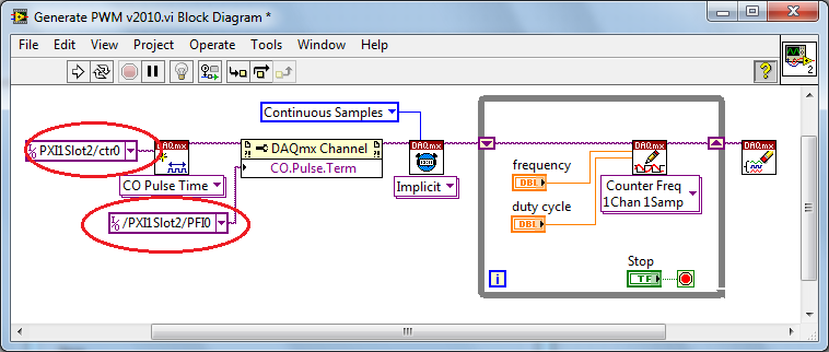
PWM - output meter (PFI4) USB-6211
I managed to control a motor based on PWM signal output via USB-6211 AO continuous. Now, I'm trying to use the Terminal counter instead.
Can't seem to make it work. NA not get a signal when link the PFI4 terminal to an oscilloscope.
I don't know wheather my coding is wrong or does not have my wiring (i.e. of USB-6211 for motor continuous). I need to use the terminal of meter that I used the analog output to a different measure.
Please advice. Attached encodings.
Thank you very much.
Front of conneting to DC motor, make sure first that the PWM is get generated correctly... use oscilloscope.
And have you changed the constant (physical terminals) for your device...?
Change to:
Dev1/ctr0 & Dev1/PFI4 and the scheme of connection must be:
-
Hi, I use USB 6211 to measure pressures, but I got too much noise. Please see the attached figure. In order to test if it is the problem of the data acquisition card. I tried to record a 5 V DC from a power supply, and I had V - 2 noise without last coherent. Power supply has been confirmed without problem. I used the DIFF mode. Could someone help this out please? Thank you.
-
USB-6211 - digital output not supported?
Hi all
I can't use the USB6211 device port... I use daqmx with Delphi7 API functions.
First of all, I tried this:
DAQmxCreateTask('', @TaskDO);
DAQmxCreateDOChan (TaskDO, PChar('Dev1/port0'), ", DAQmx_Val_ChanForAllLines);
DAQmxWriteDigitalU8 (TaskDO, 1, 1, 1, DAQmx_Val_GroupByChannel, $FF, @written, nil);I had an error in the DAQmxWriteDigitalU8:-200012 (= digital output not supported). (???)
OK, I tried to disable autostart option based on DAQmxWriteDigitalU8 and insert a 'manual' start in the code:
DAQmxCreateTask('', @TaskDO);
DAQmxCreateDOChan (TaskDO, PChar('Dev1/port0'), ", DAQmx_Val_ChanForAllLines);
DAQmxStartTask (TaskDO);
DAQmxWriteDigitalU8 (TaskDO, 1, 0, 1, DAQmx_Val_GroupByChannel, $FF, @written, nil);
DAQmxStopTask (TaskDO);Now, I got the same error in DAQmxStartTask:-200012 (Digital Output not supported, once again). (?????)
I don't understand.. 'Digital output not supported "? USB-6211 has 4 lines! What is the problem?
I want to just turn on and off the lines from code...
-Cs George-
Well, finally I figured out...

Here is the solution:
DAQmxCreateTask('', @TaskDO);
DAQmxCreateDOChan (TaskDO, PChar('Dev1/port1'), ", DAQmx_Val_ChanForAllLines);
DAQmxWriteDigitalU8 (TaskDO, 1, @dummy, 1, DAQmx_Val_GroupByChannel, @bitmask, @written, nil);Digital output lines are on port1! Corrected parameter.
And the part of the interface of DAQmxWriteDigitalU8 had to be changed (in nidaqmx.pas).
I don't know why, but the AutoStart (dummy) parameter in the DAQmxWriteDigitalU8 function is ignored: function always starts task automatically, regardless of the value of autostart. But this isn't a problem for me.-Cs George-
-
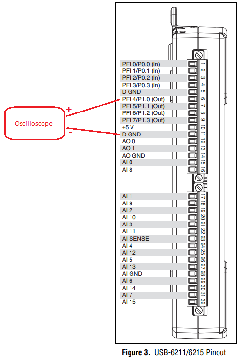
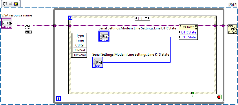
Digital output (0/5volts) using USB or RS232?
Dear friends, I need to turn on and turn off a device using a few transistors... ect. I would like to turn on/off using USB or RS232 of Labview... I just need to provice was looking for 0 or 5 volts to... Please help me.
Here's a little test vi
Now take a DMM and check the voltage levels on the line DTR and RTS of the COM port you

Should be 9 male pole D sub, careful of not to shortcut some ankles!
measure between pin 5 (GND) and PIN 4 (DTR) or 5 & 7 (RTS)
To light a LED, I would start with a LED of current low and a 10K resistor. If you have the LED's operating
 replace by an optocoupler and resistance in order to limit your current below 5mA. (Say (12V_level - 1.8V_led) / 5mA-> ~ 2.2 kohms)
 -
How I ouptut a digital waveform, it has collated and compare it to the original with a usb-6211 box?
I want a digital waveform to a circuit of output, read the return signal and compare the original to the read signal. I use a usb-6211 housing is it possible and if so, how?
Use a comparator "equals sign", mark the post as a solution if you have the makings of what you wanted.
-
Ive got an acquisition of data USB-6211 (and LabView 2009) and Im trying to get the output (5v) device to run a relay on and outside. IM using a tutorial I found on Internet to make the diagram Labview (http://www.pages.drexel.edu/~pyo22/mem639/lab-usb6211DigitalInputOutput/lab-usbDigitalInputOutput082...) and the circuit is simple. I tried to run the DAQ Assistant to test if my output was working, and it is not. I'm not sure if my connections for data acquisition are correct or not. Any help would be useful.
Thank you.
Hello NT_Mech,
Indeed, it is possible that you do not drive enough current for the relay. You can check the specifications of your USB-6211 and see that the digital line will result in a maximum of 16mA. That being said, your relay control current that is needed, you may need to run the two outputs in parallel to offer twice more common provided. Recently, I drove a Soviet Socialist Republic of a Luminary Micro Prototype Board that did not provide enough current as well. In the case of the tat, I was driving the relay by running two lines in parallel.
You can always simplify the software side of things by opening the measurement and Automation Explorer (MAX) and right click on your device and select test panels. "" ' Start ' programs ' National Instruments ' Measurement & Automation then expand devices and Interfaces. Right-click and select Test panels. You can then configure a digital output for your USB-6211 and toggle On / Off and check out.
Best,
-
Can I use two USB 6211 to replace a USB-6009
Hello
I got a labview vi., 5 output channels digital, 2-channel digital input, 2 analog inputs are necessary for the execution of this vi. Initially a 6009 usb is used to run the vi. But I have only two usb ports 6211 now, which has digital to digital for each data acquisition 4 inputs and 4 outputs. I wonder, can I use two usb 6211 to run the vi. ? What should I do?
Reverse lines are wrong, does that mean it will display 0 for false and 5 V 1.
Active drive is the normal mode of the digital output: it generates tension when said.
I forgot one thing: that you are behind the wheel of these lines, how much power do you need?
Analog output is less powerful, it can give only 2-4 mA, while the digital output 6009 could give 8 my.
-
How to troubleshoot the work of e/s digital USB 6211
My e/s digital USB 6211 suddenly stopped giving digital output. Board of directors when connected, LED flashes and passes the self-test. But refuses to give any digital output. Can someone help me please?
Thank you for your time. Technician came and found this Terminal connector was loose. Problem is solved
Maybe you are looking for
-
performance y40 Lenovo problem
I bought lenovo y40 ago 30/11/2014... I am not happy with that because his slow running on day 1... I tried many way to solve it but it doesn, t work I need few Suggetions as soon as possible, that I have to solve this problem.
-
USB to RS232 (adapter OR or not)
Hello: I have to use a USB-RS232 adapter to connect my laptop to a device for the control.The control will be through LabView library VISA. However, I found that the price for the USB-RS232 adapter varies a lot.NOR has one (http://sine.ni.com/nips/cd
-
Strange problem recognizing USB
I'm having a strange problem, recognized system repeated for some drivers, as if something (such as a USB flash drive) just to connect to the USB port while nothing has been connected. This happens so often, so you can see the small indication icon f
-
Cannot install itunes 10.5 on Windows 7 64 bit
Hello I have a problem to install itunes 10.5 64-bit on Windows 7 64 bit during installation, the following error message received "There is a problem with this Windows Installation package. A required for program This installation to complete could
-
Cascades SDK Beta 2 for Linux? Where is he?
For me, if the SDK isn't available, it's very bad news! How can I have the beta 2 of stunts on Linux? Nicolas