PXI-8232 conduit description
Hello
Colors must be in PXI - 8232 LAN LEDs (Tx/Rx)?
I have read the data sheet and get started but I Don t find this information.
What power on chassis PXI them are green, but what power on my pc top led goes orange.
However, the communication looks ok, I can send * IDN? an instruments and receive data.
Is this ok?
Hi norak,.
It seems the expected behavior for me: LAN lights be orange when packets are sent and received thorugh the ethernet. In addition, it seems that no difficulty with GPIB communication.
It will be useful,
Tags: NI Hardware
Similar Questions
-
PXI, switching boards causes the boot can´t pc
Hello
I pxi-1044 with some pxi cards (pxi-4065 / 6509 / 2529 / 8431 / 8432 / 2576 (3 borads))
and the pxi-8310 controller.
When the system has been configured for the first time, it works well.
but 2 of the borads (pxi-8432 / pxi-2576) must slot interchange (due to problems of space with their own, conectors)
When the system power, both led (on pxi chassis) and together (led controller), but windows xp does not start,
Led CONTROL switch to and restart the computer. over and over again.
I remove all the advice and check that all are recognized through MAX except the two planks of switching.
Change to a different location (never used) and the look of system work ok, pxi-8232
this Council is recognized.
What is the correct procedure to exchange some tips when MAX has a previos configuration?
I would use the slot machines that I have problems with, is it possible?
Thank you
Insteading of delete here or trying to remove, we can always Dispatcher threads.

Suite here.

-
PXI SFP 5105 configured Vs Acquisition VI
Hello
I recently started to use the NI PXI-5105 cards, I need to capture (noise level<20KHz) on="" top="" of="" my="" dc="" signal,="" i="" used="" software="" front="" panel="" to="" capture rising="" edge="" of="" an="" analog="" signal i="" was="" able="" to="" capture="" signal="" when="" it="" meets="" my="" trigger="" requirements="" same="" as="" configured="" acguisition="" example="" vi="" also="" vi="" recommended="" input="" signal freq="" ="" is="" 100khz,="" what="" changes="" i="" need="" to="" do="" in="" order="" to="" make="" this="" vi="" to="" trigger="" when="" the="" noise="" level="" on="" my="" dc="" signal="" exceeds="" certain="" point="" can="" anyone="" please="" help="" me="" with="" this="">
Thanks in advance!
Hey djo.
If I understand your description, the best sounds of relaxation as it can be a trigger of hysteresis with coupling AC trigger in order to eliminate the effects of your DC signal. You will then be able to adjust the amplitude of the noise that you are looking for as the level to which you want to trigger off. You can find information about the options available with the help of scanners trigger high speed OR under Fundamentals > trigger.
-
Calculation of the frequency of real output of a PXI-5402
I have a card PXI-5402, sitting in a high chassis. I'm only interested in the sine wave output at frequencies up to about 10 kHz. I know that it is possible to request an output frequency and then interrogate the acutal output frequency but I prefer to be able to calculate before hand. All I can find in the literature is a figure of 0.355uHz for the frequency resolution.
Is there a better description of the frequency resolution? If this is not the case, the resolution is exactly 0.355uHz or is it an approximation (to 3 significant digits)?
This webcast is a great way to learn the process including the NI 5402 5406 OR exploit to generate periodic duty: http://www.ni.com/webcast/75/en/
The 0.355uHz value is a theoretical value of the frequency rate achievable depending on the size of the accumulator Phase and clock frequency. It's the closest thing I can find on ni.com that you can use to calculate the value: http://zone.ni.com/reference/en-XX/help/370524R-01/siggenhelp/ni_5401_11_31_frequency_resolution_and...
According to me, Fc for the NI 5402/5406 must be 100M and the size of the accumulator is 48 bits. Frequency resolution so = Fc / 2N = (100 × 10 ^ 6) / 2 ^ 48 = 3.55271368e - 7
Keep in mind that the device has a VCXO frequency accuracy specification of + / 25ppm, if you have no PLL block him to a better source.
-
Hi all
play with a digitizer PXI-5124 in a case of PXI1042Q with a PXI8110 controller that runs labview 2012 (latest updates) with the latest version of the driver NIScope.
I put in place an acquisition of off-delay (by assigning the triggering delay, for example 20us) which works very well (I can tell by the signal I get delay control works correctly), but the data returned in the info wfm cluster (using the 2D version of niScope I16 Fetch) does not have this delay.
Description of the relativeInitialX within this cluster indicator indicates "is the time in seconds between the trigger and the first sample in the acquired waveform" but its never to return something around 1E-9 independent of trigger delay. Surely the relative initial x should reflect the triggering delay?
I'm doing something wrong?
Thanks for your help!
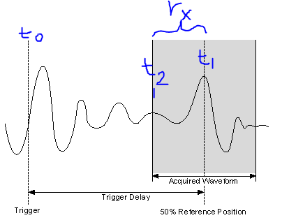
So, I made a screenshot of the image in the section "Trigger Delay" link I sent you.
Meaning of the symbol:
T0 = original moment of relaxation
T1 = time to trigger used in the acquired record (t1 = t0 + TriggerDelay)
T2 = time of first sample in the record of the acquis.
RX = relativeInitialX = t1 - t2
Response to previous reviews
«I understand what you're saying - so basically, if I want to know the delay of my trigger for the first sample in the record, I just add my delay time value to the relativeInitialX.»
- Close, the delay of the original trigger (t0), for the first sample in the record (t2), would actually be TriggerDelay-relativeInitialX
«.. . Nowhere does graphically describe where is the relative value of initialX real. »
- Right, relativeInitialX is not a timestamp, so it is not a place on the timeline, it is the difference between two timestamps (t1 and t2 above), where the relativeInitialX name.
"The trigger"record"is the straight line in the Middle, so expect relative to - 1/2 initialX record length?
- Almost correct, because the reference trigger is relativeInitialX to the position of 50%, will be the time in seconds for 1/2 the record length. (i.e. If the registration has been long relativeInitialX, 2s = 1 s). RelativeInitialX will always be the delta time between the trigger (t1) and the first sample returned in the record (t2).
- For example using the picture above: If t0 is 10 sec, Trigger Delay = 3 sec, SampleRate = 1 kHz, = 1000 record size. This means that t1 = 13 s. Our record is long of 1s (1000 points to 1 DC between each = 1 s), if t2 = 12.5 sec. If away from all these moments are absolute time, as the timestamps. So relativeInitialX = t1 - t2 is 13-12, 5 = 0.5 sec.
- As a side note, the reference position should not be 50%, you can configure to between 0-100%.
Time not yet discussed record attributes
I don't want to make you more confused, but there is another useful attribute in the waveform info that we've not yet discussed and its AbsoluteInitialX. Starting from the NOR-SCOPE help file:"absoluteInitialX is the timestamp of the first sample of recoveries in seconds..." "So, using the above image, absoluteInitialX = t2.
I hope this helps. If a part is still not clear, let me know.
-Nathan
-
RF Mux PXI-2546 driver stops working when DAQ SMU-6259 is used.
Hi, I am experiencing a very strange thing. I have a system with two 1065 equipped chassis with about 15 different instruments.
It was working fine and has done for several years. Today the SMU-6363 DAQ crashed, I tried to replace it with a spare DAQ SMU-6259. I started with switching just the daq spare in but then the computer crashed every time during the installation of the pilot SMU-6259. So I thought that I need a driver update and installed DAQmx 15.1 (previous version was 14.5). It has not made any change. Computer always crashes constantly. Finally I found that if I remove the PXI - 2546 Rfmux in the SMU-6259 DAQ system will install and work properly. But now Rfmux PXI-2546 will not work when acquiring data SMU-6259 are installed on the system. I can get the Rfmux to work if I take the DAQ and vice versa.
Why is it like this and what can I do to solve?
I do not understand why a PXI-2546 Rfmux and an SMU-6259 DAQ interfere with one another.
/ Erik
Hi Anton, thanks for your answer!
Yes, it's very strange. I narrowed down it to these two devices. I got the blue screen during the installation of the Windows driver. So I tried first update the driver OR DAQmx. Who did not have any change.
Then I tried to roll back the NOR-DAQmx driver to a previous version. Crashes stopped then, but I could not both devices to work simultaneously. In the windows Device Manager, he showed a problem for the NI DAQ PXI-2546 peripheral device. I don't know why a mux is considered DAQ hardware either. The description of the problem says "some free resources". If I could get the Rf mux to work if I unplugged the daq and vice versa.
For the last two days, I was reinstall the system from scratch. I'm not done yet because it takes so much time to do this, but it seems to be ok now. But what a pain. I started with just the driver Rf Mux (Switch).
To do this I had to download almost 3 GB! For a 2 x 4 x 1 Mux driver. Then, the driver for the installed switch some NOR-DAQmx which I had to then update and download even more.
I think that NEITHER makes it very complicated with the pilot stuff. Instead of having these huge drivers packages which supposed to cover everything, it would be better with the smaller specific device drivers that could be easily found on the web under each device.
In any case I hope it should work ok now. I wonder what will happen when I get home my repaired SMU-6363. Should I plug it in or simply do not bother because I could face the same problem again?
/ Erik
-
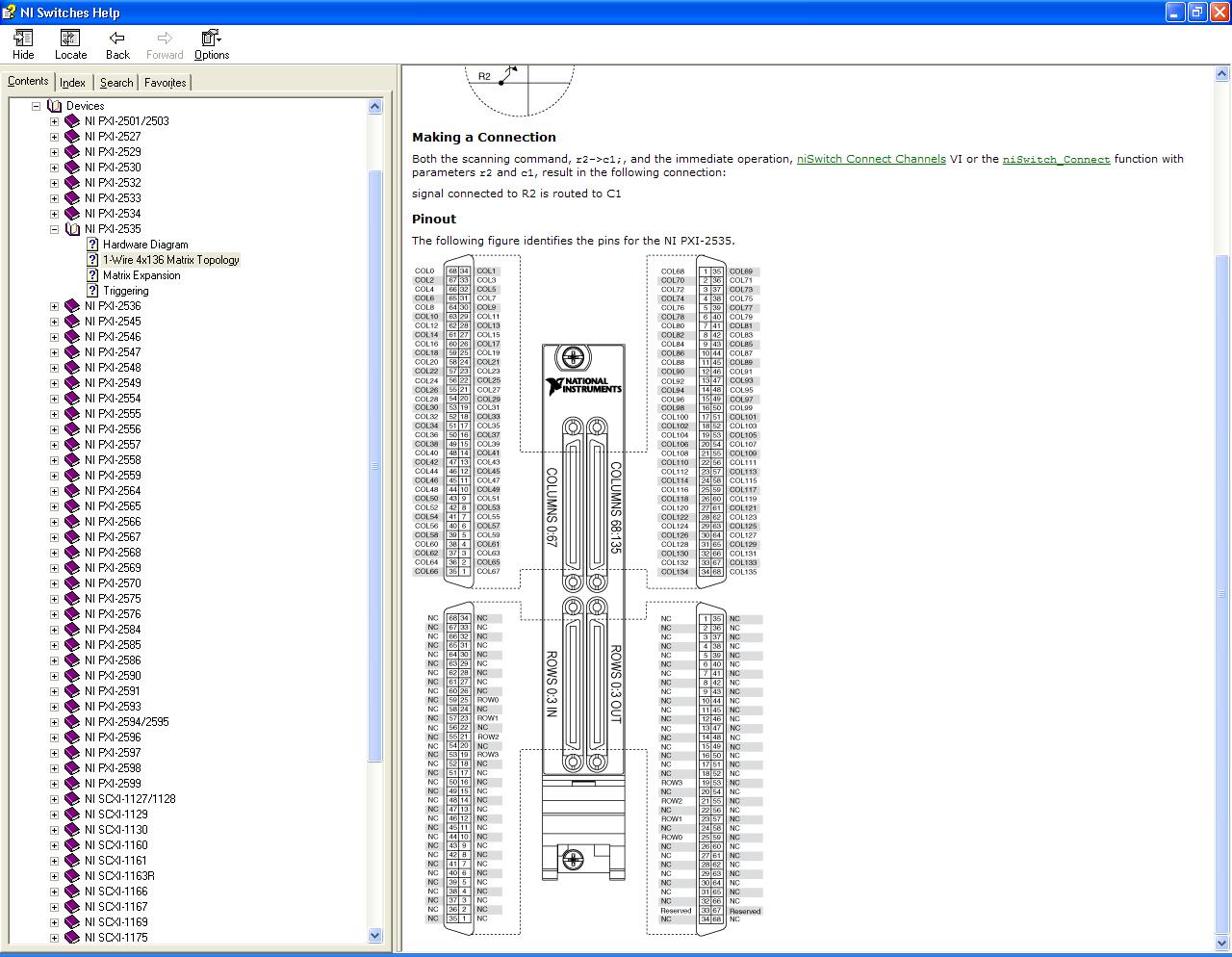
I have to build an advice for the PXI-2535 connect signals instead of using the terminal blocks. I can't find the correct manual however. Can someone you will find descriptions of stitching of connectors 68 pins for the PXI-2535 switching matrix.
Thank you
Walter
Hi Walter,
I believe that the desired pinout is in aid of switches of NOR. This manual is copied to your machine if / when you install the driver OR-SWITCH. It can also be downloaded from the following page: http://digital.ni.com/manuals.nsf/websearch/B133DDD29F0DFCC28625746E00564E56
Let me know if you have any other questions!
Chad Erickson
Switches Product Support Engineer
NOR - USA
-
Properties: General Description of the channel
Hello
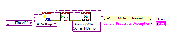
I am trying to identify my different input channels PXI I use and I would use the ' General Properties
 escription ' field to do so. The problem seems to be really simple, but I can't find how to write this field...
How can I change it? It always generates empty when I put a description in the constant channel VI or in the channel to create VI.
Thank you
Oscar
Hi Oscar,.
To write to a property in LabVIEW, you will need to click with the right button on the property node, and then select 'change all to write '. Using this property in write mode, a description for each channel can be set, which can then be extracted using the property even in playback mode.
See the screenshots attached for reference.
Kind regards
Tom - S
MEng (Hons) DRESSED
Technical sales engineer
National Instruments -
What is the difference between REFin and PPSin? Can I use the PXI-5652 to synchronize USRPs?
Hello world!
I'm working on a project I want to synchronize 8 USRPs (USRP 2920) as receivers. And it seems that PXI-5652 has a connector REF, so I decide to use it as the reference of the USRPs 8 clock. But I don't know how to connect the PPSin, and in fact I'm confused of the difference between the REFin and PPSin.
Thank you!
Jay_c salvation,
In short,.
REF is the terminal for the device USRP to accept a signal from external reference frequency (10 Mhz).
PPS is the terminal for the device USRP to accept a signal from external time source base clock (1 pulse per second)
You can see this whitepaper for a detailed description of MIMO system about 8 * 8.
Please refer to the section "time and frequency" for information specific to your question.
http://www.NI.com/white-paper/14311/en/
I'm not sure whether you can use the specifically 5652 signal generator for your application.
-
Analysis of information for the PXI Module
Hello
I intend to develop a labview program that is analysis drawn from all the module present PXI chassis (such as calibration, description of the add-on dates, etc...). Need some advice which VI Labview is capable of scanning over the disclosures in which the output is "chain" so that I can
manipulate the program labview himself. As a search for VI, one option that I see is the 'MAX Generate Report', but the results are HTML or xml (as well as my PXI
crashes when I use this feature).
Appreciate any inputs on this.
Thank you
Versil1
Hi Versil1,
I advise to use niModInst, DAQmx and DAQmx system device nodes. Examples of these functions can be found here:
niModInst: the device name of query by programming or other information using the API OR-ModInst http://decibel.ni.com/content/docs/DOC-7454
Device node and DAQmx system: programmatically obtain product DAQ device http://decibel.ni.com/content/docs/DOC-3716 names
For the outputs that are not in the string format (i.e. DevNames), you can use the flatten the string function to convert them to strings.
Kind regards
-
How can I call vi deployed remotely on target RT PXI host computer laptop
We have a system comprising a support real-time embedded pxi with labview real-time and a regular mobile host with labview. Interconnection is ENET. The two systems must be deployed I.E standalone runtime distributions. What is the best method to call s vi on the basket pxi from your laptop?
There are a lot of details to make it work, but I will offer a high-lvel description.
You can use VI server to call code on machines of RT.
For each application that you want to call the side RT create a source distribution. Those to the node RT then using the correct path on the RT node using VI server to open and run the target live FTP
Have fun
Ben
-
Error codes 12, 31 - PXI my system does not work
I tried to solve the erros on my pxi system using the software compatibility MXI-Express BIOS 1.3 - Windows 7 64 bit/7 x 86/XP x 86/Vista Vista / x 86 x 64
This software is intended to solve error code 12 or 31 showing in windows Device Manager. But this software does not support any system with material that contains several bus root PCI Express, only those with bus single root. But according to this software, my computer has MULTIPLE ROOT PCI EXPRESS BUS. What to do next? Windows just don't recognize my PXI system. There are two screenshots of the error.
My description of the system:
Dell precision T5500 workstation
Windows 7 64 bitPCIe-8371 x 4 connected to a x 8 slot
Controller of SMU-8370
SMU-1075 chassis
Step-down converter frequency PXI - 5600 RF
Digitizer PXI-5142 OSP
Converter RF PXI-5610
SMU-5442 AWG OSPI appreciate the help.
Filipe I think I can help you here. With the T5500, we should try to slot 2 or 4. We saw some problems of special interruption with Dell 1 slot and you can or can not see this behavior too. Unfortunately, I have all the details on this issue. However, there are also a known issue with Dell BIOS that limits the PCIe bus range, which can cause unexpected behavior when you extend your PCIe via MXI-Express bus.
That leaves us with two options:
1. we can update your BIOS to not have the bus number so low limit range
Dell may have a BIOS available for the T5500. You can contact Dell Technical Support and maybe ask an other BIOS that has been released - it's not available on the Web.
2. we can try to take advantage of the v1.4 MXI-Express BIOS software compatibility, supporting multi-root complex
You need to register for the beta to ni.com/beta software. Once approved, you should be able to download and install accordingly.
I'll send you a PM about #1. I would like to help us as much as possible.
Kind regards
-
PXI-6551 device data Underflow
Hello.
I have a module, PXI-6552. I need to enter my DUT (ADC) out after a very long and very precise vector sequence. And I want to loop through this sequence of more than 1 000 times (at the average of the results).
The following script works:
script ADCcapture
generate marker0 of vecsetup (0)
Repeat 1000
generate marker0 of vecsample (424)
end repeat
end of scriptHere are the sizes of waveform for each wave listed:
vecsetup = 280 cycles
vecsample = 262 060 cyclesMy sample = 512 MB record length and the number of records to capture = 1 001
The first marker in my script is my trigger start for my CQI. session. The following markers are triggers of the advance.
As I said, this example works, but the "vecsample" waveform is much smaller than it should be. It should be 5 times as large, but I don't have a lot of memory.
Fortunately, most of the 'vecsample' is a sequence repeatedly to keep living clocks (in my example above are just exhaustively written in the form of ongoing vectors).
I know I can't nest, and I know now that I can't embed instructions more than 55 inside my finished loop (repeat 1000).
Then, I tried to break my my 'vecsample' signal break up into 3 sections that I could "split the difference" between the size of memory limitations and the script of vector:
script ADCcapture
generate marker0 of vecsetup (0)
Repeat 1000
generate marker0 of vecsampleA (424)
generate a vecsampleB
generate a vecsampleB
generate a vecsampleB
... (Note: I have exactly 50 copies of 'generate vecsampleB')
generate a vecsampleB
generate a vecsampleB
generate a vecsampleC
end repeat
end of scriptHere are the sizes of waveform for each wave listed:
vecsetup = 280 cycles
vecsampleA = 1 660 cycles
vecsampleB = 4 884 cycles
vecsampleC = 16 200 cyclesvecsampleA contains unique things initially, including the previous sampling period output ADC.
vecsampleB contains 1 221 best x of the model 4 time keep alive clock that I need.
vecsampleC contains unique things at the end.Yet once, my record sample length = 512 and the number of records to capture = 1 001
In the end, this generates the same number of cycles as the previous example:
1 660 cycles 4 884 * 50 + 16 200 plus 262 060However, when I run this new script, I get an error:
Exception detected
Detail: [-1074115901] Windows error 0xBFFA4AC3
Description of the DLL: DAQmx 200316 error has occurred:
Measurements: Device data precision passing. The device was not able to move data quickly enough to deal with the frequency of sampling for the active script.Perform the operation at a lower sampling rate, or are looking for the following in the current script: markers can be too close together, waveforms is too small, wait may be too short or subsets may be too small. If you are using an external clock, the clock provided might have disappeared during your generation.
State code:-200316
Sorry for the long post. Any help is very appreciated!
BrianPS: I found the following topic regarding this issue, but it has not helped me to understand my mistake (as it seems that my markers and waveform sizes seem to be big enough):
http://forums.NI.com/NI/board/message?board.ID=70&message.ID=10306
Hello Brian,.
I've recreated your problem on my side, thank you for the detailed description of your problem, it makes it much easier to understand what was going on.
Although I'm still looking at the root cause of the problem, there seems to be a problem with the number of orders in the repeat loop. You need 2 less commands within the repeat loop. This can be demonstrated that the problem by moving two of orders outside the loop, keep the same number of lines in the script, but less than two lines in the loop to repeat itself.
In your case I want to double the size of the vecSampleB and only run 25 times. This should allow you to start going forward.
With regard to the underlying issue, when I find I'm going you know.
-
Change the Description of several photos
I emphasize the relevant photos and change, the Description field within information (Cmd + I).
But when I click on out of the box Info, he asks me if I want to change the description of 3 000 photos (pictures of this year, not only the photos that I have highlighted).
No idea why it does this? Is there another method of updating the Description?
Thank you
How you change the descriptions is exactly how it should be done. Select the photos in the browser, open the Info Panel with ⌘I, and enter a new label.
MacBook Pro with the retina, OS X El Capitan (10.11.5)
Your profile signature OS X El Capitan is still valid?
I had a similar problem when running left El Capitan. Occasionally, Photos would change the description field of all the photos in the album, I was displayed and not only the description of the selected photos. And for the fields title, this would change a title that I had chosen.
On the Sierra, I noticed that the browser is sometimes loses focus for the cursor. When I use the Trackpad and not by the mouse. If the Info Panel is opened for a few selected photos, a reckless trackpad gesture can move the focus to another album in the sidebar and the Info Panel passes to this album, and then by typing in a different title or description will show the warning about editing thousands of photos.
-
How to export pictures of the photo program to include descriptions?
I would like to export photos and descriptions of the photos from my photo program although. I had no luck. Y at - there a trick to this?
Check the box "include the title, keywords and description"
If the full export window is not displayed, click the v to the right of the JPEG to open the full window
LN

Maybe you are looking for
-
How can I scroll through email in the list?
Before the last update, I was able to click on the arrow down in an email, and it would be then just move to the next on the list email. Now he asks me to confirm if I want to just open and read the next unread mail. Blah! not what I want. Having an
-
Is anyway I can make a bookmark when I click it it will run a program installed on the computer?
Hello all - I regularly use Firefox for my internet-streaming/navigation needs, but to access a program that I use for my work that I use internet explore. I was wondering - is anyway to create an order or entry in the part of the location of the boo
-
How to erase history of cards in 9.2.1 iOS
How to erase history of cards in 9.2.1 on a 6 s iPhone iOS?
-
"laptop HP 2000: why should I keep my keys for a second for my keyboard display what i type.
"Why should I keep my keys for a second for my keyboard display what i type.
-
Loading of the connected battery, do not... (found the solution that worked for my Dell Inspiron
Well, the charger is plugged, but he says not charging. What happened twice. I would have thought bad battery or bad, but fortunately the first charger, that it took place just after buying a new hard drive. I did a hard reset on the battery and that