question of Labview base
Hello
I use labview 8.6.1
When I try to use the formula, even with a very simple formula node:
x ^ 3-x ^ 2 + 5
When x is equal to 10, he gives me the power of-6,1...
but there are 905,
and a few times it gives me an error of type integer required: for example: y = x ^ 3, at the entrance of th is 10.
smercurio_fc wrote:
I see that everyone is picking up on the ripe fruits.

Its a Monday

Tags: NI Software
Similar Questions
-
LabVIEW base, protocols supported system of development and the basic features
Hello
I ask this question here because I can't find that information on the web, or I get the technical support e-mail response. We are interested in acquiring a license of basis of Labview to start development to develop test for simple automation systems. The basic idea is to have a card with digital, analogue i/o, common seria interfaces: RS232, Ethernet, I2C or SPI. All this to interface HW under test. A single port for communication with the PC (USB, Ethernet, RS232).
We would like to know:
(1) what protocols are supported by the Labview Base development system package.
(2) if the license mode allows you to integrate MATLAB/C/C++ code.
(3) in general, where a document that provides details on the characteristics of the Labview. We were not able to find a manual for it. Just this very basic with informaton purchase link: http://sine.ni.com/nips/cds/view/p/lang/no/nid/1385.
Kind regards
Jose
Have you looked at the page 'Buy' for LabVIEW? http://www.NI.com/LabVIEW/buy/
Basically, I think that LabVIEW base supports everything in terms of basic Windows protocols, but does not include LabVIEW RT or FPGA (for CompactRIO/FPGA targets) but you can use series, ethernet, etc. DAQmx for windows (and also the instrument 3rd party drivers). It doesn't have the enhanced math library or the application Builder so that you can not create executables/installers - you will need run your code in the development environment.
Alternatively, you can call external code .NET / C dll through the call library function node. You will not be able to incorporate Mathscript, because it is only in the complete edition upward.
-
A few questions about LabView and (fairly complicated) thermocouples
Hello, I intend to read [this is only 16] 20 thermocouples (type K - in data acquisition, assistant it is J but it will change soon). I use two devices, usb-6008 and usb 6251. I had a BT program (see table below) and I have some questions/statements that need to be confirmed:
1. I plugged my devices, put DAQ Assistant on the Panel, the temperature chose->-> K thermocouples and I scored channels by dragging a slider 'clicked' on all channels. So now I'm able to read all channels, right?
2. I have added a few thermometers and digital indicators with them to have an accurate reading of thermometers in digital data.
3. I've read a few articles on tracing multi channels on a single diagram of wave and I want to apply to my program. Basically, I don't know how to run, I need to make a table and plug it on the graph of the wave. The thing is, I don't know how to do it.
4. I would get 1 sample per second 1, I added the delay time = 1000ms. Unfortunately, DAQ Assistant says it works like 1 k samples by 1 Hz.
I am quite fresh in LabView and currently I view tutorials and other things. I would be grateful for advice.
BTW, I can't test if it works with thermocouples connected because I don't have at the moment and the place where I would be able to test the program has very limited access

-
Hi all
I have attached three labview questions with my answers. Please check and give your comments.
Thank you
Hi lavanya_sri,
The answer will be C... It is a model of vi which will give impetus to any application, which allows a quick programming...
Thank you and best regards,
srikrishnaNF
-
Hello HP,.
My laptop is completely useless after 3 years of normal use.
I sent an email to the HP service center after they sent me heavy price quote as follows:
Fix for fraction very price at a local mobile shop, which set the motherboard by replacing a few shorted out chips with new ones, replaced the hinges and fixed same base compound and finally got.
This saved buying me a new laptop + Win10 pro which will not come with most of the new laptops.
Nobody called me using HP's India team.
in any case thank you Jeffhelp and kevin-T.
-
question about labview diagram
Hi all
I'm working on labview with fieldpoint modules. Why can't connect me FieldPoint i/o Point constant directly to reading of the (polymorphic) FP? He said "I have connected 2 terminals of different types. But in some way, I found some manuals on NOR who said these 2 elements might in fact be connected. I use Labview 7.1.
Kind regards
Nicky
Thanks to you all. I solved this problem.
-
Simulate the structure of the event in the LabVIEW base?
I have a basic version of LabVIEW (v8.6) who doesn't have the structure of the event. I found it was quite embarrassing monitor the status of several controls (action after clicking a control depends on the State of the other control (s)). Especially if I want to add another function (control), the effort exponentially increase with the current number controls
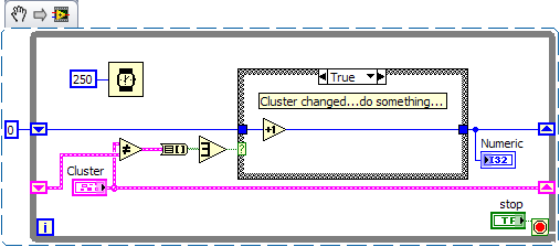
I had an idea to simulate the structure of the event using "shift register. First, I will provide all the values for the controls in a cluster. Then I'll put the cluster in a while loop and compare the value of the cluster to its previous value (xor the registry change). If the result of the comparison is false (none of the control is changed), the program moves to the next iteration. If the XOR result is true (one of the control has changed), then the program goes into code (it will pass what control has changed and the entire cluster) event management. So for each change of control, we can write an independent code to process the event. After processing of the event, the event was allowed.
Here are some of my ugly code currently used to monitor multiple controls. And I think rewriting using above idea so there is less chance a hiden bug.
Comments, suggestions?
I'm not quite sure what I'm looking for on your photo of your block diagram because it seems that only the lower quarter right in your code. I would do the following to detect a change in a cluster without the structure of the event control:
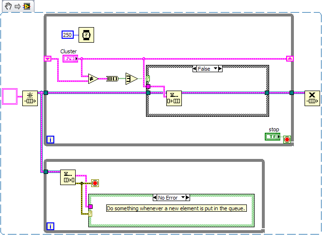
The basic package include the notifications than us? You can put your "event management" in another thread by this method:
The advantage here is your main loop of the program is not "bogged down" every time that a change in your cluster held. It also allows to separate the code so that it is cleaner.
Hope that helps!
-Fisher
-
Hello again,
I am trying to change a line in my VI database and have had difficulties.
The first image (modifysimplesingle) presents the database update works correctly, however, I don't want to simply modify a column value. I read the help document on data update VI, which led me to believe that it is possible to enter a cluster to update the whole line.
So I tried this (modifysimplecluster) and are slow to achieve success. Am I wrong to interpret this? I also looked at the example provided by Labview, copying their syntax. If I'm wrong, what would be the best way to change a single line, provided that the primary keys and foreign keys sometimes (if that makes a difference).
Looks like you provide data but not the names of the columns. Provide an array of strings at the entrance of the columns so that the function knows to apply the data for columns that.
-
Question for LabVIEW FPGA DRAM
Hi all
How can I correctly address the 128 - bit DRAM memory? I have the Bank DRAM 0 set as a memory of 128 bits, set up in my design as a CLIP. I realize it's a wide RAM on 32-bit. I had a National Instruments AE do the original design I've been adding to. He said that the addresses needed to incrementing by four with each entry. Example: if I had to write in consecutive addresses, I would write to the address: 0, 3, 7, 11, 15 etc, and I would like to send 128 bits to each address. My address is calculated as: (number of pixels in a line of video + line * (number of pixels per line) for a picture of the video). So I take my calculated address and add 4.
However, I checked an example in the finder example: example of integrity hardware flexRIO/IO/external memory/memory. In this example, 128-bit data is sent to the memory and the address is incremented by 1 (instead of 4) each cycle clock as valid data.
Who is this? Section of the help for this function is ambiguous.
Sets the address in external memory for reading or writing. The physical data bus for external memory is 32 bits wide (4 bytes). Each unique address value represents 4 bytes of data. Therefore, the total number of unique addresses in external memory is equal to (Memory Size in bytes)/4.

Note  The memory interface exposed to LabVIEW FPGA is 128 bits wide. As a result, each memory write or read operation accesses four different address locations in memory. The memory controller latches this signal value only when you issue a new memory write command by asserting the Command_Write_Enable signal.
I'm confused by the 2nd paragraph "every Scripture memory or read operation four access address locations of memory." Does that mean I increment the address by 1 to get 128 consecutive bits 'locations' (Yes, I know, that's 4 words of 32 bits in memory), or do I increment the address by 4, in the order of words of 32 bits 4 by 128-bit single transfer?
Thanks for your help.
-J
Hello J,
I want to clarify my previous post. There are two ways to access memory DRAM, CLIP (that you have described is what you do) and using the memory node. As noted before, the DRAM is 128 bits wide. When you write to the CLIP you basically write pieces that is the width of the databus (in this case 32-bit). Therefore, when you write a total of 128-bit DRAM, you place 32 bits in each address. The address being the width of the databus, then you write with a writing & the address 0, 1, 2, 3. Then the next write will be 4, 5, 6, & 7 and then address 8, 9, 10, & 11 and so on. In this case, you must increment your address by 4 whenever you write. Note that you start at 0, then 4, then 8, etc 12. In your previous post, you were out of a figure.
There is also another way to write in the DRAM memory, and it is through the node of memory, which is what is used in the example that you are pointing out. Here, LabVIEW takes on some of the thought, and instead of being the width of the databus address, they are the width of the entire segment of 128 bits. So when you write to DRAM here, you only increment 1 whenever address because they refer to any segment of memory. This contrast with the CLIP, address 0 of the memory node interface match the addresses 0, 1, 2, 3 in CLIP mode & and address 1 of the memory node would correspond to 4, 5, 6, 7 in CLIP mode addresses &. If you do not write an integer of 128 bits for the memory node, then the remaining addresses in the data block are filled with "junk" so that the address remains constant.
As I mentioned previously, it is the most effective writing in chucks of 128 bits so that you don't waste all of the DRAM. I hope you find this explanation clearer.
Brandon Treece
Technical sales engineer
National Instruments
-
I'm very new to LabVIEW and MATLAB and have had problems making my LabVIEW code compatible with MATLAB scripts I wrote.
In my LabVIEW program, I have simulated two channels one NOR 9237 USB - DAQ and recorded outgoing data in an ASCII .txt file (using the Save to ASCII/LVM vi format). I have also written a MATLAB script that reads this .txt file, removes the header and records digital data in a .txt file. The script works well in MATLAB and does exactly what I need to.
I tried to use the MATLAB script node in LabVIEW to import the MATLAB script that I wrote, and create the new file .txt (with little success). I imported my entire script in the MATLAB node, but the LabVIEW program run any of my statements when I try to run the program. I tried to type in the first several orders of my MATLAB code in the LabVIEW command window, but it keeps returning errors when I try to open and read the .txt file I created with the LabVIEW program using 'fopen' and 'fgetl"from MATLAB commands.
Any suggestions would be much appreciated!
Rachel
It is not a specific VI or function that will do that, but that does not mean it's hard. In your VI you are already save data to a file of measurement using writing to the file of the measure, which is configured to save a .lvm file (which is just ASCII), so why are you re-register? Who is the consumer of these data? If LabVIEW, you can simply use the read measurement VI file to read the file directly. If you want to save the raw data for another program to use and then just use the write to the spreadsheet file VI. This will create a text file using tabs to separate columns:

NOTE: When you wire dynamic data in the input array of writing on a spreadsheet file dynamic data conversion VI gets automatically added.
-
Develop a VI that calculates the pressure according to the temperature of an ideal gas:
-
Simple question of LabVIEW on accountant Boolean signal off structure case
Hello
In my current program, I am trying to carry a Boolean signal (elapsed time) on a structure case to stop a while loop.
http://zone.NI.com/images/reference/en-XX/help/371361E-01/loc_bd_casestatus.gif
The loop on the left is basically what I want to do again every time I do this, I get a green tunnel box with a White Center. It I cannot run the program by saying that there is a missing assignment in the tunnel. What can I do to work around this problem?
White Center means that there are some cases where you do not have a Boolean value wired to the exit tunnel. The tunnel exit value is the value that is wired slots in the case that runs, a value must be available in all cases.
There are two possible solutions.
(1) [normally preferred wire] a Boolean value in the tunnel of release in all cases. Exit tunnel will then travel to a solid color.
(2) right click on the tunnel and select 'Use default if unwired' you will notice that the White Center will get smaller. It's like a constant false wiring for each of the cases with no wire. The drawback here is that it can hide errors in logic. You might expect over something, but not out of the Park, and no syntax error was reported.
Rod.
-
Beginner with questions of the base layer
Hi all! Been reading / looking for a solution to my problem, but can't find it - so now I ask the group. I'm not a trained Designer, plus a young craftsman/teacher-type elementary school who want to have fun with pictures then purchased the package of the educator of the Adobe with the new Mac Book Pro last year. CS3, I used PrintShopDeluxe () widely, and iPhoto, Photoshop, etc...
I am not able to understand the functioning of the layers. I create / setting up a certain print doc size (pixels). I opened pictures (including large size I have handled/shrunk by Preview) and bring them into the doc very well. But! each photo has another layer and the first picture disappears when I add the second photo. THEN the layer panel goes to the most recent photo and I don't see anything on the other photo! I thought that the info would build in the layers panel, but no, in that I have to return to the file open the recent item to see the other picture that I put. I've exhausted all the possibilities I can muster from drop-down menus. Why not the layers panel building of information with every thing I add? Maybe I'm not adding things the right way?
I know that I'm over my head with this program, but the tutorials are wonderful and so is this forum. I am determined!
So, thank you to breathe a big sigh and scribble a fundamental aid for me.
Marg PDX
You say you're "Opening" files. Who would not simply open a new document
with only the single photo placed inside?
Try to 'place' images in an active document rather than "opening" your
images. To place an image, click on file > Place.
-JM
-
Basis of LabVIEW Development with Compact RIO device software
Hello. Currently, I have the LabVIEW Base development software package and have been using it with DAQ Compact devices for the acquisition of basic data. I would now like to start integrating controls in my system, changing to RIO Compact for deterministic real-time features. My question is that I would be able to build applications for the Compact RIO system using only the basis of LabVIEW Development package without updating immediately? Maybe some features are not available for me, but could at least get a good start like that?
A CompactRIO embedded time real operating system (RTOS) called VxWorks you need to target the deployment of LabVIEW code to the device. Classic LabVIEW screws you will have been written so far are built to target general purpose operating systems (GPO) such as windows.
To create screws that are deployable to STSOp, you will need the real-time Module that is not included in the basis of LabVIEW. As a result, to take advantage of the embedded FPGA, you'll need to install the LabVIEW FPGA Module as well.
As long as you have the FPGA modules and in real time, it seems to me that you should be able to control these devices with LabVIEW Base. Without these software components you will not be able to create an instance of the device target your LabVIEW project.
-
System base with yellow question mark device? -Portege 4000
Recently installed XP Pro on a Portege 4000 from a retail disk (not toshiba drive)
Thought I had found all the drivers, but I have a yellow question mark against "Base system device" in Device Manager. Don't know what it is, so I don't know which driver to install.
Any ideas appreciated.
concerning Mick[Edited by: admin on 19 February 06 21:21]
Hello
I recommend to check which device unknown need a driver.
See this Toshiba document and follow the instructions.
http://support.toshiba-tro.de/KB0/TSB57014E000QR01.htmAfter this procedure, you must know which driver you need.
Then go to the page of the Toshiba driver and download the required driver.
Maybe you are looking for
-
Hello world I was looking for help with my new IPhone SE I recently made the last General update and found that, after turning my phone even once, the screen flickers now and then I was wondering if anyone knew how to fix this?
-
Made by Satellite A210-128 supports ATA-300 (or) ATA - II hard drives
Hello is it my support ATA-300 (or ATA - II) of Satellite A210-128 hard disks?I want to replace the original ATA-150 drive currently installed.If it detects to buy a faster ATA 300 drive, or will not be the laptop can use hihger drivespeed?Thanks for
-
We're the o/p of runningsfc/scannow
We have problems with IE 8.0 goes "NOT RESPONDING" and also the top and blue bottom lines don't always come with the new screen. or the site when it comes to display. To check to be sre that all Windows XP administration etc are all in their origina
-
I have a disc of class to graduation of my granddaughter (5th to 6th grade) In the Media Player component it lkooks like this: ------------------------------------- Unknown DVD title one ------------------------------------ Chapter 1 Chapter 2 Chapte
-
I forgot the model of lock screen
can not unlock my phone, I have forgotten model. What should I do?