Readings
HelloWhat are the incorrect readings?
Can anyone tell me a good document to understand the incorrect readings?
Rgds
S
Hello
Have a look here...
http://download.Oracle.com/docs/CD/B14117_01/server.101/b10743/consist.htm
See you soon
Ben
Tags: Database
Similar Questions
-
heart rate iWatch gives sporadic readings
I use my iWatch everyday to monitor my workouts and recently the watch started giving crazy readings. It will start to normal and 10 minutes in practice, it will say that my heart rate is in the 1940s. Then it will go up to 180 + and then back to normal for maybe 10 minutes. Meanwhile it greys out for maybe 3 to 5 minutes and said measure... I unpaired and reset and it never does not. It's very frustrating, because when I do a 1 hour training session I should get an average heart rate of 140-160 and now I get 80-110.
Anyone else having this problem? Are there any current patches?
Hello
Apple says that, even in ideal conditions, Apple Watch may not be able to save a reliable heart rate monitor each time reading for everyone.
For best performance of the sensor of heart rate during the training, Apple suggests you consider your clamping beforehand watch band and he loosen again thereafter.
The sensor is also likely to give better results for workouts that involve rhythmic (for example running) rather than the irregular movements (for example boxing). Other problems that can affect the performance of the sensor include the perfusion of the skin and wrist tattoos.
If your workouts involve flexing your wrists (for example what weight lifting, for example), it can help to keep your watch a little higher on your arm, the joint in flexion.
More information:
Your heart rate. What it means, and where on Apple Watch you will find. -Apple Support
Use of the workout on your Apple Watch - Apple Support
If you continue to experience problems, for more consistent measures, you may wish to a heart rate monitor external matching / Bluetooth chest strap for your watch:
Use the Bluetooth with your Apple Watch - Apple Support Accessories
-
MacBook Pro. 2 different readings of free memory
My Macbook Pro.10.11.6/ 2012 is a bit slow. It shows also the 2 readings of different storage. Under Macintosh HD icon desktop reads 328,82 GB free. But in the section "about this mac" reads 271 GB free. Difference of 57 GB. It is a bit slow?
Hello
It's a big difference, something that I would try would be to repair and check your drive. You can do this by following these steps:
- Restart your MacBook Pro
- When you hear the startup tone, hold down the command + R key until the apple logo appears at the bottom
- A dialog appears, select the Disk utility
- Select your Macintosh hard drive and under the first aid tab, click Repair
- Once the repairs completed, restart your mac
I hope this will fix the problem, good luck!
-
Re: Incorrect accelerometer readings
I have a strange problem: shortly after the start of my tablet, the accelerometer is weird. Therefore, the acceleration of the screen is always upside down, and it does not meet the rotation of the tablet.
If I read the readings of accelerometer with a test program, the trend is good, but the zero level is incorrect. 0 g, X denotes + 4 m/s, Y indicates-9 m/s and Z watch-5 m/s. What explains the problem with the rotation of the screen. The only solution seems to be a reset.
Is that what I can do to solve this problem, or do I need to bring it back? I'm just inside 6 months since I bought it, so I need to know soon...
PS: This is a Pro to excite 10.1 16 GB, I think AT10LE-A108 is the official type.
> I feel it was a rogue background process.
> It is difficult to say which, but I learned that any application can recalibrate (or spoil) the accelerometer.Sometimes its very useful restore Android system, but also the tablet to the factory settings. Where the Android system was confused upward through an app or a process, this reset should solve the problem.
That's why I think you should check it out in case you no it did not in the past. -
Very high readings of temperature CPU of the Mac Pro 8-core 2007
I have a Mac Pro 1.1 updated to level with two Intel Xeon X 5365 CPU and firmware 2.1. The system has worked very well for months. However, I'm worried about CPU temperature readings. Assuming that the readings are correct, I have no explanation for the difference in typical 30 degree Celsius between the processor and the heat sink.
Is it possible, that the CPU exceeds their life expectancy?
During a stress test, I can see the following typical readings:
CPU core 87 C / 189 F
CPU a heatsink 58 C / 136 F
B processor 91 c/196 F
CPU radiator B C 59/138 F
I use new thermal paste Arctic MX-2 and tried various measures, including polishing of the surface of the CPU and the heatsink using sandpaper grain 1000. Nothing has so far had no effect on temperature readings. There should be enough good contact between the heatsink and processor during the installation, because they stick well enough to remove the heatsink again.
Max TCASE. According to the operating temperature -1333 http://ark.intel.com/products/30702/Intel-Xeon-Processor-X5365-8M-Cache-3_00-GHz-MHz-FSB is 63 degrees Celsius.
According to http://www.intel.com/content/dam/doc/design-guide/5400-chipset-memory-controller-moyeu-guidelines.pdf the Quad-Core Intel® Xeon® 5300 series include a function of on-chip temperature sensor. The heat sink provided by Apple has a temperature sensor, which seems to be fixed directly on the coper plate that touches the CPU head spreader.
Given the following quote from the same document:
TIM's performance is sensitive to degradation (e.g. breakdown of fat) over the life of the processor because of the temperature of the phenomena of cycling. For this reason, measuring of the processor given TCASE value can decrease over time according to the type of material of TIM.
Anyone know if the IHS on the CPU is soldered or whether they used the thermal paste between the IHS and the die of a CPU? In the case, perhaps it could explain the current temperature readings.
Any ideas? Thank you!
Your temperatures look a bit high, but not outrageous. The temperature measured on the Silicon of heat will be always higher than the temperature measured on the radiator. That's what the radiator is supposed to do, leads away from the heat to the fins, which would measure even more cool.
Your Mac allows to adjust speed of the fans to the top in a loop of feedback, founded the temperature of these measures. You can place a floor under your minimum speeds of fans. This can be done with the tool similar to some tool you already use, like the SMC fan control.
If the processors to exceed their safe operation temperature, your Mac will perform a sudden uncontrolled power off.
-
readings of Veristand instruments with a remote system
I'm new to the National Instruments and Veristand material and I'm trying to use an instrument with Veristand to see if I can get readings of this instrument. I use a PC with Windows Vista and I am connected via a network to a PXI-8108 controller in a PXI-1050 chasiss chassis. The instrument is just a thermocouple which I use to become familiar with everything. The thermocouple is connected and the connection SCB-68 block which is connected to a PXI-6221 multifunction data acquisition in the chassis. I am able to create a task in MAX under remote system and everything seems to work. What I want to do is to get the readings in Veristand, and I don't know if I need to create a custom device that is related to the acquisition of data somehow, or if there is another way to do it. I created the DAQ hardware in the system Explorer, but I see no way to link the real DAQ hardware on the remote system. I wonder if anyone can help with this.
All advice is appreciated.
Thank you
You can read the value of your thermocouple directly from VeriStand channel, but the process is different than using MAX.
In the system Explorer, add your DAQ hardware that is wired to your SCB-68. Make sure that you specify the same name (i.e. ' Dev1'), which is the make up something, you also that you have imported the peripheral canal which hangs to the thermocouple (i.e. "ai0"). There is no way in System Explorer to specify that this channel should be scaling of thermocouple. VeriStand initially served this string value value brute power. However, you can set the limit high and low for this channel to something small as +/-1V, since thermocouples have very small readings.
You add the balance to your system separately after the deployment of the system definition, you have created the target of RT. For this to connect to the target using the workspace and select the tool to the workspace on the Tools menu called channel scaling and Calibration Manager.
In this dialog box, you will see your TV listed DAQ. Navigate in the dialog box assign an appropriate scale of thermocouple to your channel. Once this is done, the target will remember the scale for this channel until what crush you.
I would like to know how it goes...
-
DAQ in Veristand readings do not match the MAX readings
I have three accelerometers attached to a block of SCB-68 connection that is connected to an NI PXI-6221 data acquisition on a RT system. I have created a task for each accelerometer in MAX and have tested each one to see that it works and gives appropriate readings. Veristand, I created a workspace file to test the accelerometers and I the acquisition of data created in the system Explorer. After the deployment of the system definition and running workspace, I created three simple graphics and connected ways appropriate to each curve. I reduced tensions in the same way exactly, I put on the scale the to the MAX, but for some reason, one of the accelerometers gives tensions that are far away from where they should be. The other two accelerometers work perfectly and one that does not works perfectly in MAX. So I don't think that there is a problem with the accelerometer, it just would not work in Veristand for some reason any. I wonder if there is someone who can at least have an idea of why something like this could happen. I have all three accelerometers that are related to the same connector block and I wonder if put too much in a block would do something like that.
Any help would be appreciated.
Thank you
For all those who can do I understand what the problem is. The default setting in Veristand read channels of differential measures, so anything connected to channels 8 or below is mapped to both channels, (e) and has (n + 8), where n is the number of the channel. For me to use the accelerometers in the way I set up the I just need to go to unique benchmark measures ended (CSR) in the system Explorer.
Once again thanks for your help.
-
DAQmx showing not readings to multiple channels
Hello
I am trying to acquire values of temperature of 3 consecutive using a task DAQmx channel as shown in the attached photo.
I have a loop of producer-consumer for fast reading and writing samples in a file.
To specify the channels, I typed in the box connected to a terminal of "physical channel" (not shown in picture) as follows:-SC1Mod2 / ai2:4. This is to acquire a reading of analog channels 2, 3 and 4. The program must then write a file reading on channel 3.
The code works perfectly if I purchase samples of 1 channel only.
When I try to acquire multiple channels, I don't see readings on one of the task of acquiring Wired Digital indicators.
I would appreciate your input on what might be wrong with the code.
Thank you.
kumv10 wrote:
The broken wire seen in the photo is the result of adding more channels to the task of acquiring. I managed to get around this by specifying a different, but even with an intact wire data type, the program is not displayed readings since the 2 remaining channels.
Instead of use for dynamic data Type, then the channels Split, just use an array of Index to get your three values.
-
WSN-9791troubleshoot erratic readings
We have a WSN-9791 with four WSN - 3212 s. All 3212 s have power supplies OR (don't not running off battery).
Three of the four 3212 s give erratic readings. For example, the following was recorded today to a piece that should be around 70F:
17/10/2012-15:38:20 187,8
17/10/2012-15:39:20 148.9
17/10/2012-15:40:20 139,0
17/10/2012 15:41:20 - 1548.9
17/10/2012-15:42:20 37.2
17/10/2012-15:43:20 158.8
17/10/2012-15:44:20 39.5
17/10/2012-15:45:20 111.5
17/10/2012-15:46:20 206,4
17/10/2012-15:47:20 - 6.6
17/10/2012-15:48:20 188,6
17/10/2012-15:49:20 262.5
17/10/2012-15:50:20 74.1
17/10/2012-15:51:20 102.0Location appears to play a role - so far two 3212 s different that give erratic readings have been very stable (with reasonable readings, too) when they sit on my desk, but become erratic when moved elsewhere in the building. In addition, one of the erratic nodes goes stable days, then several erratic days, then back to stable. When a node is erratic, all four thermocouples of this node are erratic.
Thinking that this might be a problem with the electrical noise, I put one of the 3212 s on a UPS - no difference. I also changed the channel without wire used for a couple of different parameters, without modification. I moved the 9791 at different locations in the building, again no difference. Thermocouple type parameters have been triple checked.
Any ideas on how to solve this?
Hi James,
WSN-3212 is sensitive to analog loops mass and power supply noise and maybe it's what you see. To determine if this is the problem, try the following.
1. electrically isolate environmental thermocpule probes
2. connect the ground terminal GND D of the WSN-3212 (PIN 10, 12, 14 or 16)
See you soon,.
Brian has
R & D Product Support Engineer | WSN/network DAQ/University
National Instruments
-
Ghost NI USB DAQ card readings
Hello
I have a question about the behavior of the NI USB-6218 data acquisition card. Right now I use Labview to take several current readings of different channels to HAVE it. I use resistors 250 ohms for each channel just as the instructions say to make the current readings. I had an incident where he has been disconnected one end of a resistance at the entrance to the port. I expected to see the reading go to zero, but instead, he began to piggback off the coast of reading one another channel give me a kind of 'reading ghost' because there was essentially no current crosses. Playback of disconnected channel displayed the current reading of the canal connected even while values went upwards or downwards. Can someone explain why the DAQ card would do that? and anyway to avoid this to happen?
Thank you.
A data acquisition uses a multiplexer to send a signal to the ADC. Due to having only 1 ADC, you will get this effect if the ability has no way to bleed. There is no way to avoid this if you disconnect the side DAQ, leaving the open input channel.
You could try adding in some amplifiers specially designed for the shunts of currents. I have used TSC103IPTwith success. This amplifier gives you a single output is completed. But I don't know what will happen with these if you disconnect one side of the resistance of the amplifier.
-
4071 PXI get negative resistance readings
Hi all
We are working on a system where we measure current leakage and resistance using a PXI-4071 with some other gear as well as a map to relay SMU and 2530 b..
The main problem is that for some measures of resistance we are seeing negative values as k - 200 or - 300 k. The digital multimeter has been in the range of 10 M. My understanding is that in this mode, the applied voltage is 10V and the test current is 1uA.
For me to see a negative resistance on some paths, the voltage must be opposed the 10V and superior to 10V. Is it a specific way of thinking? SMU is switched off and disconnected from the circuit when the resistance is measured.
It is not all EHRS that show this negative tension. The EHR is all passive devices (connectors) and so they do not have any large capacitances that could store a tension that I see. I take 5 readings with auto zero done when initially 5 readings.
What causes these negative readings? The connectors are immersed in a saline solution and there should be an open between the points to measure circuit, but when they start to fail a resistance can be seen.
Any thoughts would be much appreciated. Please let me know if you want more details.
see you soon
Peter
Peter,
To answer your questions, Yes, if the digital multimeter reads - 200 k there is opposing tension on the DMM. If you use 10 M Ohms then the opposing voltage serait.2 V and if you use the 1 M Ohms then the opposing voltage 2V. Also the negative reading is also caused by the flow of the current is in the wrong direction, because if there is a negative voltage then the current flows the opposite direction.
You can check the voltage at the terminals of the resistance while taking the measurement of the resistance using an other DMM, as a handheld DMM computer. It is more than accurate enough to check the voltage at the terminals of the resistance.
I hope this helps,
Brian P.
-
manipulating data with several readings
Hi again,
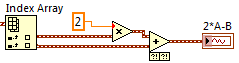
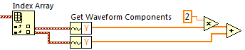
So I can read the tensions out of the terminals of NI USB-6009. Now was that reading analog1 and B be analog2 reading. I want to calculate something like 2 * A - B. I can't understand how to do this.
I can read the values together and watch them on the same chart, but I can't deal with them. I enclose the file in which I read the values, put them through the filters and then display. But 'data' is only one variable, although there are two readings in it. I do not know how to separate one from the other.
Thanks for the help.
cartonn30gel,
Playback DAQmx returns an array of waveforms, each element of the array represents a data channel.
To split the individual channels out there, use primitive Table of indexes in the table Palette:
You can then use regular numeric operations on the waveform, or if all you care is the actual reading, you can get the table of voltages measured waveform using the primitive to get elements of waveform in the waveform Palette.
Thicker wires in LabVIEW represent arrays that contain several similar items. The waveform data type is a convenient way to manage measurement data because it combines information in time (t0 and dt) with the data table measured (Y).
I hope this helps.
Simon
-
LabView Thermocouple temperature readings
I use the SCXI-1001 with SCXI-1102 and SCXI-1303 (LabView 8.2) in record temperatures of thermocouples type k. My problem is that the temperatures that I see on LabView are off by about 5-10 ° c. AND they stray +/-10 ° c throughout the day. What I've read, I think that this could be linked to the CJC. Right now, I just CYC Source set "Permanent" with a value of "25". I can make adjustments to it to help with the lag, but the drift just of temperatures throughout the day and the readings are again incorrect. The room temperature changes somewhat in the region where I have this configuration, and drift in temperature seems to be linked to that. For any help or suggestion would be appreciated. Thank you.
Hi Zawer,
Your SCXI-1303 module has a welding temperature sensor cold precision thermistor, so the 'Integrated' parameter must be supported. Try resetting the 1102 able and Automation Explorer, then restart LabVIEW. Is thrown this error yet?
-
How can I convert 9213 readings of TC in temperatures on FPGA?
I use a cRIO-9076 with 9213 module to capture readings from thermocouples (type K). Is it possible to convert these readings (voltage of the FXP Data reading) in the temperature on the FPGA values? My goal is then to use these temperatures to control an analog output through a PID.
According to the specifications, the 9213 should be able to read 8 TC to 100 Hz. I would like to be able to run as fast PID TC can be read accurately.
I couldn't find an example of code that does the conversion of temperature-voltage on the FPGA. The example of getting started is send you the values of voltage of TC to the processor, RT, then converts the tensions in temperatures. I was not able to get that to run faster that about 50 Hz in one analysis comparative VI. Once I have add any other code to the RT target, I think I'll have to run a lot slower than 50 Hz.
Any suggestions / examples / whitepapers can you tell me?
Thank you
John
Hi John,.
Take a look at the Started.lvpoj get 9211 from the Finder of the example. You can use the same screw of this project to convert volts to your 9213 module temperature. In order to preserve the accuracy of the readings, it is recommended to convert the voltage to temperature in your host VI. The rate of your control loop is not very fast, only so you should be able to run your PID loop and to convert your data to the frequency of 100 Hz to your host VI.
-
Problems with encoder motor switching noise readings
Hi all
I wanted to ask advice with a hardware problem which seems to be pretty common.
Here I describe my request:
We are controlling an electric actuator for robotics application. We use encoders to take position readings, and we need to perform analog acquisition for other measures (for example, the force measured using strain gauges).
The problem is:
In summary, I have problems to properly acquire position readings of a linear encoders quadrature and also a few analog inputs. The cause is the switching noise generated by the drive motor that we use (which is an engine without Stricker of CC Moog BN-23-23).
Our acquisition platform is an NI PXI-8106 with a PXI-1042 q chassis. We have two possibilities to acquire the signals. We have a multifunction DAQ series NI PXI-6259 M and a FlexRIO NI PXI-7951R with one module DIO NI PXI-6581R.
The switching noise have a frequency of 30 kHz. In a scope, we see a series of peaks of noise which are present only during a short period of time (approximately 1/10th of the duration of the noise). The rest of the time the noise is not present.
The Accelnet amplification module that powers the electric motor gives us a clock signal synchronized with the noise (whose frequency is approximately 1/4 frequency noise). This clock signal provides a way to solve the problem of analog acquisition. We can use this clock to make an acquisition stamped with an external clock in LabView connecting the clock on a spit of PFI or FPGA card. But the noise is also corrupt this clock signal (we get an error daqmx us warning of possible defects in the clock signal and also to stop the acquisition). I believe that to solve the problem of encoder we can also solve the problem of the analog acquisition.
In the encoder readings noise makes our County to counter upward or backward gradually fast enough. We can get an increase in the position of about 10 cm per second with no appreciable movement in the linear actuator.
It would be a great help if someone could put the solution he uses to solve this problem.
Thanks in advance for your help,
jespestana
PS: I stress my conviction that we have a hardware problem, because we have only bad readings when the electric motor does not work. I am therefore convinced because we have already done reading encoder and analog with the help of other players, such as hydraulic cylinders. So, I think that it is not a problem with our software (of our LabView VI).
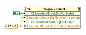
Hi jespestana,
I don't know why the noise could be the cause of your encoder can increase more slowly... However I have a suggestion on the map of the M series (6259):
M-series cards have a digital filter integrated on the lines of the PFI (see the user manual of M series). Looks like the noise is a series of 3 ~ US of impulses (1/10 to 1/30 kHz). Of the available filtering frequencies that you can set on your M series is 6,425 US, which must ignore the impulses (high or low) that are less than 6,425 US. You can configure the digital filtering with a property node DAQmx:
One caveat is that the driver only allows you to configure the digital filtering for entries counter on M Series devices. For example, you can use a digital filtering directly on your task of encoder, but not for your sample clock HAVE. A workaround can be found here, which is to set up a dummy counter job to define the PFI filter for your task to HAVE. If you use the same PFI line for your encoder and the task to HAVE it, you should be able to just set up the PFI filter through the task of the encoder and worry for the workaround.
Regarding the RIO Flex, I think that you could implement something similar on the FPGA, but I'm probably not the best person to comment on this subject. It would be probably a lot more work to use the DAQmx API's built-in filtering.
Best regards
-
because I don't have a sensor now, I am currently generating a table of random numbers 30. After each 5 readings a warning should be given to the user 5 readngs are completed. This cycle must be repeated. the size of the table is 30.
Please help me, waiting for response as soon as possible.
Once I have the transducer, I'll take 30 analog samples and then after each 5 smaples this wraning will be displayed din a new VI
Use a while loop with a delay time representing your sampling interval.
Use is equal to the count Terminal to see if 4, then 4th iteration = 5th sample.
Use a box structure. The real deal will only run on the 4th iteration.
In the case of true place a Subvi with your message of your choice in the front panel. Go to the properties of the VI window and set ' open the front panel when it is called.
The condition to closing of attention is not given to your description.
Consider that rather than usign a Subvi to do this, you can use the "dialog box one/two/three button" or "display message" live in the palette "user interface and dialogue."
Please try it out and send your own VI. Do not provide us with a working solution.
Kind regards
Maybe you are looking for
-
I don't like the new Format but Id rather have the songs alphabetically not by the artist and the song. as was the old Format.
-
Windows update install could not install with error 0x8024d007
I have a situation where on one of my computers Security Center is not on so I can get no updates etc, I installed service pack 3, but this made no difference. The system I am running is XP Home edition.
-
How can I get the contact photo?
Hello everyone. I work in my own app to make and end calls by program but I can't find a way to get the contact's photo, I saw the API documentation but I tried to get the pic and move it to a QImage without success. Can I get the contact name and nu
-
problem with my computer laptop hardware/driver.
I have a laptop lenovo z570 to hv with win7... from AFTR, on the desktop, the last icon is selected automatically... even whn, I opened my man or recycled bin that opens the last shortcut... BT when I press any key in keybrd the problem disappears...
-
Repeated installation freeze (with screenshots) - suggestions?
I have a problem with the installation of Flash. Running Windows 7 64 bit on a Lenovo T410. Antique Junker, but do well other than this Flash issue. The built-in flash of Chrome is fully operational. There is facility for Firefox 34.0.5 (the most