Regulation PID on FPGA
Hello
New year wishes to all.
the Pid of the FPGA control block (I think even on windows), LabVIEW is to differentiate the process variable instead to differentiate the error, is it even?
Respect,
N. Kumar Malek.
I do not have design control / PID toolkits installed for the moment as I rarely use these days, but when I finally did, I ended up implementing my own. This should be a good starting point:
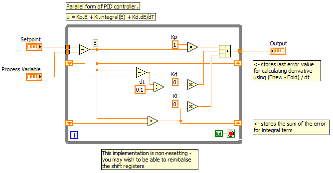
It's about as the basis for an implementation of PID parallel I can find (for Windows - where double, if on the FPGA you should probably use floats). You can extend to enable the controller reset (depending on the LabVIEW application where the registers at offset).
I have attached the VI (LV2012).
Tags: NI Software
Similar Questions
-
Regulator PID very slow to reach the value Point and zeros process Variable when it should not
Hello
I am using a PID controller to regulate the emission of a filament current in an ion gauge, but I'm running into several problems.
The first and less important, are the controller of PID VI takes at least 5 minutes to get the current where it needs to be. Is it possible to speed this up?
The second and more important, are that the PID controller tends to zero the process variable before you start the process of getting the close process of the target value variable. This can be seen in the attached VI: I write 5.8 volts voltage filament - something I did at the beginning to try to get the controller PID for the process close to the target faster - value variable but when the PID controller starts to do his thing, he kills the tension before anything, rather than rise of 5.8 V.
The attached VI is a single which has these problems. VI actual ion gauge controller I've written has the same problems, but in a form even more frustrating. I have a while loop set up for the filament voltage to where it should be (using a PID controller) first and foremost, then a loop of data acquisition, which also includes a feedback loop in the form of a PID regulator to maintain the filament voltage. When the second PID controller starts to run, it concentrates the tension that the earlier had set, taking another 5 + minutes to reach the point where we can take data and giving us 5 minutes of false data in the process!
Does anyone know why PID controllers are behaving like this, and what can I do to fix/work with this behavior?
Hello
It seems that PID VI will always be 0 for the first iteration. You can, however, use the advanced PID VI and set up the first iteration in manual mode. After subsequent iterations, you could then define this automatic mode and there will be a transition smoothly. I think this will give you the desired behavior.
-Zach
-
Regulator PID that VI is not expected
I am writing a multichannel PI controller using the PID vi (in the PID toolkit). All channels have the same point of setpoint, output range and PID adjustment of the values. In the help file for the vi of PID, he says:
"The array instance DBL this polymorphic VI can be used in PID control applications multiple loops." In this case, the primary input array length will determine the length of the output array. Other paintings of entry need not necessarily to have the same length as the main entrance Bay. Other paintings of entry will be resized by this function for the same length as the table of primary entry as follows:
- If the input array is longer than the main entry, the input array is truncated to the length of the entrance Bay. In the table of additional values are not used.
- If the input array is shorter than the main entrance Bay, the last value of the input array will be repeated until the size matches that of the Bay entrance.
In this way an input value that should be used for each calculation output didn't need to be specified in the array passed into this function repeatedly. Instead, the table can consist of a single value that will be used for each calculation output. »
> I take this to mean that I don't have to laboriously repeat the same data for each channel; That is to say. I can wire a table 14 poles "process variable" entry of PID.vi but only for example number 1 on the set temperature etc. In practice, however, this does not work. See attached vi (NB this is not yet complete, so you can't run it!) and note the broken wires!
Dave
Hello
The reason he has a cut wire is on some entries have that one value wherever the array type needs a picture on all inputs, even if the table has only one item! You can see in the code, I went back that everything I've done is but a building block to convert table effectively the type of a single variable in a table with only one type of data. I also had to change analog writing for multichannel and change the data type of the shift register, I presume this would be necessary.
Kind regards
-
Regulator PID in SignalExpress?
Hi all
I'm about to order some equipment of NOR and in addition to data entry, I need to write a controller for a device external (PID, whatever) - for clarity - I want to read a voltage from a sensor and the output of any other voltage to the actuator to set the sensor output for any value, I need. Nothing complicated.
So can I do this in SignalExpress? Or I need the full version of LabVIEW?
It seemed to me documentation online is it possible to route an input signal through various filters and on an output channel. If this is true then I guess I need to know if the components to build a controller (addition/subtraction, integrate, differentiate, etc.) are available to the signalexpress (?) If they are missing, is it easy to import them from the version/download full from any share/something else?
Thanks in advance
Ben
Hi Ben,
Signal Express is a configurable application software to make the acquisition of data and logging, NOT control applications. But, if your application consists of adquiring and the release of tension or another type of physical phenomena through a conditioning of signals, this is your software. For example, you can buy the voltage, current, temperature, voltage...
You can download the Express Signal with a 30 days evaluation license:
http://Joule.NI.com/nidu/CDs/view/p/ID/1378/lang/es
During these 30 days, the software will keep the entire feature. You can also read the tutorial that I send you in this post.
However, you cannot change environmental Signal Express import of new features, but you can use hardware filters if they are supported by the filters module and the software of hardware in the tab add a step > treatment > Analog > filter. Alternatively, you can do additional processing with the options on this tab. Have a look inside!
If you're Spanish, you can contact us directly on 91 640 00 85.
Saludos!
Jesus
-
Hello!
Can I use a regulator PID for MCB2300 programming?Hi knob.
I see the problem now. The PID Autotuning VI launches dialog boxes to user as the Automatic Tuning Wizard, which are not taken in charge by the embedded targets. Embedded applications are designed to run without user interfaces. You will need to use the VI PID and adjust your order manually, PID which will give best results in any case, I thought.
-
PID does not return any output...
Hello everyone...
process sbRIO on board and using the audio and vibration Simulator
below I have attached my RT + FPGA... code to control the speed of the fan... using PID...
RT. front panel
set range
1000, -1000
set point... 5000 RPM (speed is the parameter)
PID GAINS...
the values calculated at the time of the executin arbitraty... KC = 1, gain full (Kc * Ts/Ti) = 0.011718,.
derivative gain (Kc * Td/Ts) = 0
other considerations
Maximum speed of the fan is 6000 RPM
tachometer on the vibration signal Simulator is 2 impulses/turns
the speed is measured accurately
Manual disturbance can be given by varying the analog output voltage
If the pid is introduced into RT it works fine...
but, when the pid (in fpga) is introduced not able to disturb and also not output to
all other parameters is reset (final rpm, out outputanalog)
all equal to zero
This data set is meaningless... I suggest that you check that you actually save the correct values, and you have the wired PID controller correctly upward.
There are times when (?) heated, but the speed does not change. Also there are times where speed (?) has a step increase, but there is no change in voltage. You can also see places where 5V is applied but different speeds are generated. Of course, it would be much clearer if you labeled your data, including units.
Open-loop can the system actually achieve 4000 rpm with the applied 5volts? Try to start with a set point which is at the centre of its work.
The ramps are integral single action? What gains have used here. You should try proportional only first of all, make sure that everything is working properly and then only start watching full action.
-
Note: I know that this post can be considered off-topic, but I think my problem is with how I'm trying to control my instrument (not the PID controller); That's why I posted my question here. Please correct me if I'm wrong.
Seen: I have a power supply programmable dual channel, a wheel and a PID controller.
Find: The encoder feedback, I would like to use the PID controller to control the outputs on my power supply.
My solution
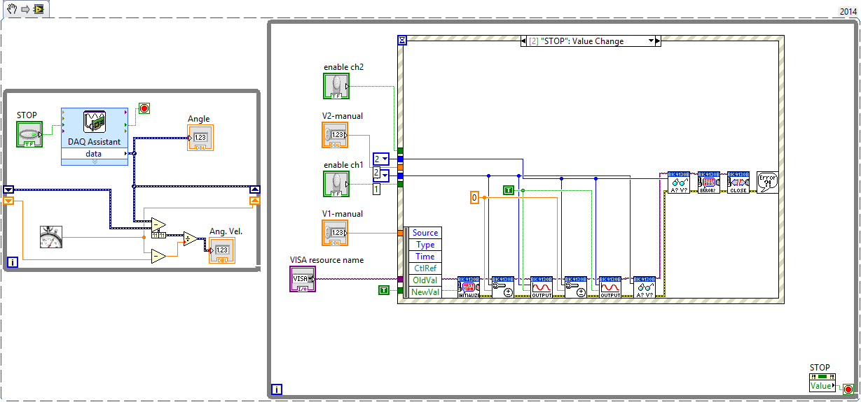
Using the VI below, I can read the encoder and adjust the power supply without a regulator PID. The left loop reads the encoder data, and the loop on the right allows me to "manually" resolve tensions on the channel 1 and channel 2. Specifically, a structure of the event inside the loop on the right send recent tensions 'channel' (as I entered in the respective controls) power supply.My problem
However, the law while loop is not "react" when I can replace this "manual" voltage control a PID controller. The power supply simply does nothing even though the PID is indicative of the power to do something.Attempt to correct
Mode "highlight execution", I noticed my left loop would complete many iterations, but data in the loop on the right had to run only one time - and even in this case data arrested when he reached the structure of the event.Questions
- My PID control loop does not work because the PID loop (left) runs too fast compared to my power supply loop?
- What would you recommend? Filers?
- (Slightly unrelated) How should I wait the last strains of my diet?
The two blocs 'read out' in the loop of power should allow me to display the real tension of a channel. However, these data are always a 'step' behind the actual reading.
For example, I put V1 = 12V. Food reacts and displays 11.998V on its LCD screen. However, my LV code displays 0V (or any busy V1 value). If I change again V1, say V1 = 7.9V, then the power displays 7.989V but the code LV displays 11.998V. What I am doing wrong?
Writes that if I set V1 and then set V2, my LV code displays the value of the V1 correct but not the last value of V2.
Well, the first problem is obvious. You initialize the power whenever the event occurs. (DON ' T DO THAT! ")
Initiallize ONCE
Loop ON
Read the answer
Feedback monitor
Adjust the stimulation
until the output is requested
Output control loop
Close resources ONCE
-
How do the dynamic set for the PID control point
Hi all
Here, I have a question about regulation PID setpoint. Now, I've built a program in which the vi PID setpoint. may not be a constant. But I want to improve the program by allowing the set to be dynamic, saying the dynamics, I want to say maintaining the setpoint change over time, it could be like a sine wave, or better could be a custom shape. Could someone tell me how to fill that?
Thank you
CJ
-
Manual of PID for transfer Auto smooth
Hello
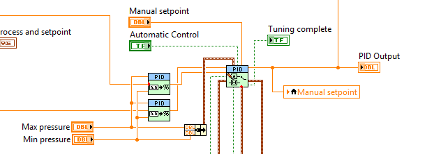
I am using the PID command for a pump to ISCO syringe with manual Steplessly in automatic control, but I can't seem to make it work.
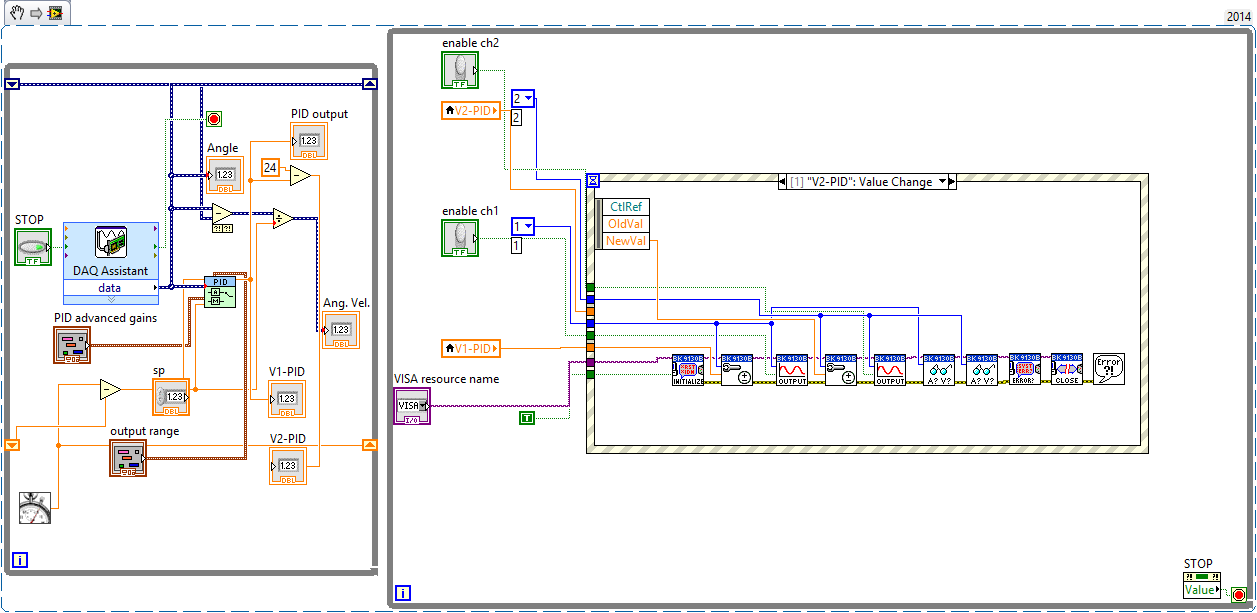
This shoot-syringe has an entry and exit pressure and is used to apply a force to keep the vertical movement of a constant of the sample. The amount of applied pressure is related to vertical displacement by an equation that appears in the attached VI. This VI aims to apply a variable force according to the displacement of the sample in order to try to keep moving 0.
Here is some general information on the pump that I use:
The pump is autonomous and can independently maintain pressure regardless of the LabVIEW PID controller. The pump only takes pressure of LabVIEW controls and maintain this pressure until another pressure control (I think that the pump integrated into the controller itself is a regulator PID.)
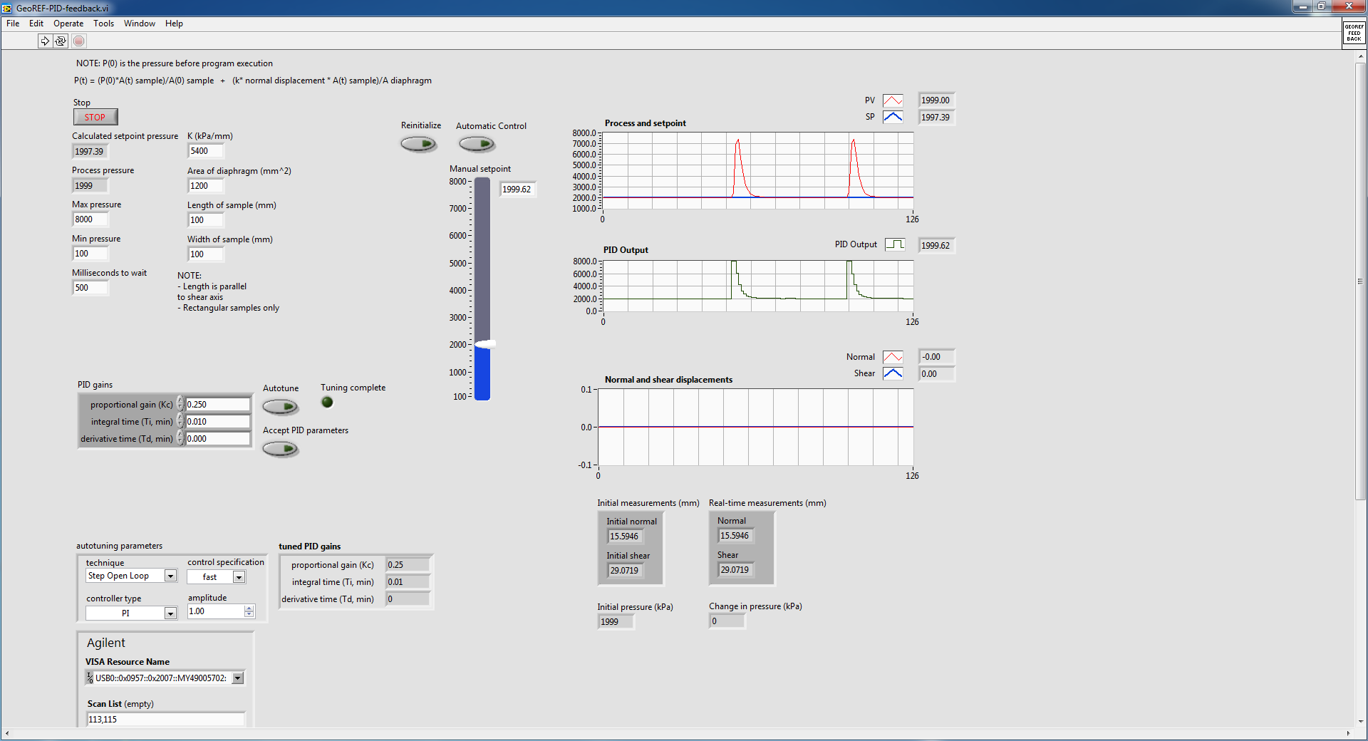
The problem I have is if I start the VI with the pump at a constant pressure (using the hand control with advanced PID VI) and crossing the wire to automatic control, the advanced PID VI immediately shows the pump to adjust the pressure up and then slowly bring it down to the steady state. This happens even if the hand control pressure is stable and identical to the auto set pressure. This following image details what I'm talking about:
The pump is in steady state, as shown in the diagram of pressure and the value in manual initially and then toggled mode on automatic control (designating the huge bump). I did it twice to show what happens when I go back. Manual automatic is without suddenly, because I used a local variable to constantly change the manual set temperature.
I did some troubleshooting and experiment and here are some of the results that I found:
1. when going from manual to automatic control, PID regulator sets the maximum pressure and then slowly bring it down to the set value
2 when it is cold from the VI in automatic mode with true to reset, the PID controller sets the pressure at a minimum and then slowly bring it up to the set value. This occurs even if the value of the original process is close to the set point (feed the actual value in the PID controller before execution also does not help.)
I also tried to play with the gains of PID in VI and found that if I turn off the 'I' and parameters "D" (together the two to 0), I no longer suffer from the huge bump, but the PID controller can bring the real set point value as there is always a lag.
I don't know if this is a result of bad PID tuning, but after the initial bump in the transition between manual and automatic, the PID controller seems to be able to maintain the correct pressure well.
The reason why I am using a PID controller rather send the pump controls (since it can independently maintain pressure) is because it is much smoother.
In the attached VI, there are a few side screws that are called that are specific to the pump and the LVDT used for detection of vertical movement. I do not think that they have an effect on why I don't get a transfer smoothly without jerking, so I only put comments to explain what they are doing.
I found another thread in forum with a similar question, but none of the solutions posted it seemed to have helped me. Here is the link to this thread:
http://forums.NI.com/T5/LabVIEW/PID-manual-to-auto-bumpless-transfer/m-p/3180609#M920098
Thank you.
Best regards
Victor
Your topology is not quite how we recommend that you make the transfer smooth. Can you do something like this?
Who will do manual setpoint pressure (units) and you need to update your gain, but it should follow. What is an option?
-
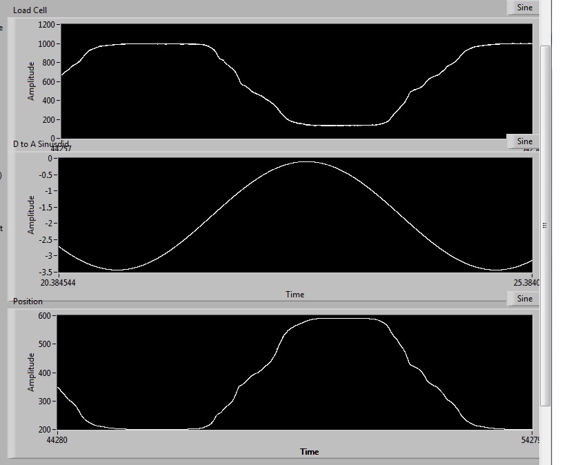
Im having trouble with an application of linear motor control. I'm using a servo-motor/converter to power a linear drive. The player is running in current/torque mode so that the output power/force is proportional to an analog input that is sent to him (no setting parameters). For this particular application, Im using the express vi 'set up fake signal' to create a waveform of sin that is used as the target value then inturn helps determine the voltage sent to the engine and thus, out of power. The tension of a load cell is then read through PCI-6014 and convetered at a level that can be compared with the output of analag, scale factor for the torque mode. There is also a PCI-6601 used to determine the position, but should not be relevant here.
Without PID. Using a load cell, I see that the wave of fishing is truncated at the top and bottom, it rises to fast in response to the tension and then from the trays. The reverse happens when unloading and it reaches a low load to soon and there is also the truncation. I will attach a figure which can demonate the problem better than I can explain it.
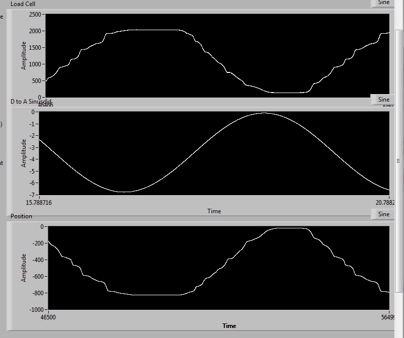
Without PID. This isn't a saturation effect, but as I can raise the amplitude of the input voltage and the force will follow the same type of waveform, but again the load levels. Ill. attach a screenshot 2 new levels of load of 2000lbs.
I can look at the levels of current/voltage output of the command servo which feed the linear actuator and that they are the sinusoids perfect, after all what is the input voltage, if guided by PID or not, its a mirror right, without truncation as occurs in the above figures. There is also no problem of speed or acceleration, it is well under the speed limit, that this system can work, IE under 0.25htz and it can run 50htz to these displamcements. So, these are not the problems.
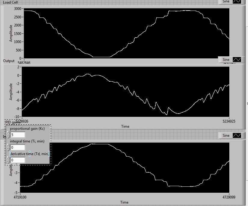
As I understand it, the PID is commonly used to correct this type of problem and is standard with machines that need to produce force in this way... Infact, I learned from the people who make the drive I use to fix this type of problem. Yet, Im could not get it to work. I tried to change the P term accoring to the N? I have the document below and dosent seems to correct the loss of crete, so Im doubtful the I terms or D will do much (and have tried without success). I'll attach a third screenshot and link in the general guide for the PID below
http://zone.NI.com/DevZone/CDA/tut/p/ID/3782
with the PID, with P increases so some departures of instability
Ive tried reinstallilng labview on a different computer, with PID and get identical results.
I'll join the code I help him, not that I'm waiting for anyone to find, its big enough.
Any help is greatly appreciated.
Jimmy,
If your control loop does not work with a deterministic timing, the highest rates of change of the setpoint to the situation, so the quality of the control loop also limits the frequency of your sinuses. However, the loop itself is always on to 2 kHz, so the loop time and jitter of the same order of magnitude, then it will be very difficult to get a system of stable control with this configuration. Reduction in the rate of control loop is also not a solution, because the linear motors are very dynamic systems, requiring control loop series kHz.
To improve the situation with your current setup, you can always try to better structure your vi, delete dynamic memory allocations and so forth, but the improvements will be very limited. In fact, there is a reason why NEITHER a lot of success with products such as LabVIEW RT or compactRIO and the reason is the deterministic behavior of these platforms that is required by the dynamic closed-loop control applications.
To answer your question on the amplitudes: regulator PID tried to generate an output signal, which translates as the set value - PV = 0. So for example, if your load cell outputs 0.5 V/N and you want to generate a force of 10 N, the set point must be set to 5. In other words, the scales of the setpoint and the PV must match, but this does not mean, you must necessarily across the PV before you go to the PID controller. Instead you might evolve set points to map to the copying. The advantage of this approach is the fact that you don't have to do calculations online on the feedback signal, because you could precalculate a set value table before you start the move. This approach would calculate you your calibration data in the matrix of setpoint values.
If you follow this method, you might also think of using a control chart of standard movement as a PCI-7352. This Council deals with all onboard, real-time control tasks so no LabVIEW RT is necessary and you can move the locker bays precalculated in the memory of the Commission (contouring mode).
I hope that gives you some ideas how to proceed from here.
Kind regards
Jochen
-
error 200141 on parallel angular measure
I've been browsing the pages of discussion about this error, but so far the proposed resolutions have not worked. I have included my highest level as well as the necessary Subvi VI in a zip folder. On the schema of the structure BUSINESS here is "RELAXING" Mode There are 2 ZIP files: 1 for the case which does not cause the error but 200141 poses problems of CPU load and the other that uses QUEUING but excites error 200141.
A summary of this VI is that there are 2 meters read the angular position of 2 motors in parallel. In conjunction with the tasks of meter is a READ DAQ which reads in 2 analog signals from 2 Motors indicating the amount of torque being applied. A time meter & signals are read, they are treated by a regulator PID VI & the control signal is sent by a WRITE of data acquisition. The counters, READ, & WRITE all tasks are synchronized by the sample to the WRITING task clock & resident in the same loop. Unfortunately, WRITING on FILE & SIGNALS VI GRAPHICS place a heavy burden on the CPU that the rate of loop iteration is seriously hindered. To reduce this burden, I added a parallel loop & employees QUEUING to show data & file. It resulted in significant improvement of control performance. However, 200141 intermittently error especially if the user makes changes in the PID tuning parameters. This error not manifest on the VI that doesn't have the parallel loop with QUEUING. I would like to use FILES but is unable to avoid this error, threatening!
SUGGESTIONS? Oh, by the way I use a USB 6229 DMA data acquisition is not an option & are of the highest level VI "Integrated servo control". If you respond with any VI I use LabView 8.5.1
Another possibility that I'm exploring but have never been implemented before, is that when error 200141 that the VI is not completed successfully. Therefore, the tasks may not actually STOP or CLEAR. Is there a way to make sure that the tasks are DISABLED before execution of the loop & this could be a source of error 200141?
The VI "without problem" as far as I know always completes successfully even if an intermittent DAQ error occurs.
-
Hello
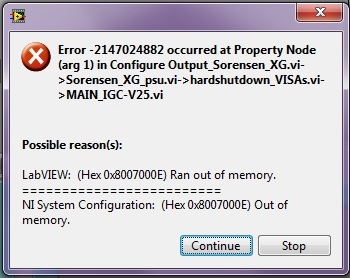
I have a problem with a programmable power recently bought Sorensen XG 60-14. In my application (LabView 2012), I use this power to fuel a cooler through regulation PID Peltier. My code sets the current performance of the PSU to the all the 1 sec. My application works without any problem for days, until like 4-5 days, and then I get a crash.
The first problem is that, when I get the error, the LabView gives a pop up window asking continue so or stop? This is really not good, since my code should stop completely in case of error (I wrote my code in a way if there is error, he must close and stop all other material, like other power supplies). I used the official "lvlib" Sorensen to make my own screws, see set in the zip file.
In my code, I first tried to use the "configure Output.vi" Sorensen VI official with very little modification, but usually, I got errors and accidents after 2 or 3 days. So I decided to get rid of dish-sequence-structure and also unnecessary allow exit on every play, so I set it too.
Now I use the Output_Sorensen_XG.vi 'configure', and I call it the "Sorensen_XG_psu.vi." So in my high level VI, I call these screws with 1 Hz frequency.
First, I here insert the photo of the first error that I consider a pop-up error:
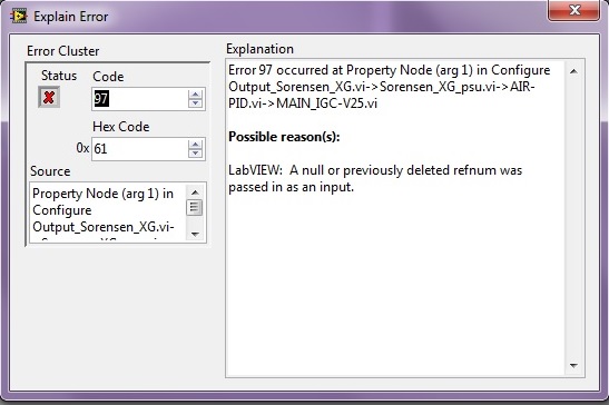
After clicking 'continue', I get the following error, but I guess that the first error above is one, as the following is generated due to closed resources?
What can be the problem? I created leak memory somehow? I should close some refnums in the Output_Sorensen_XG.vi 'configure' after each iteration, there is a lot of property nodes?
I hope someone can help me... thanks a lot!
EDIT: actually, I realized that the second jpg is the info error relevant, since the first is just a mistake of a Subvi, where I try to shut down the power supply in case of error, and that the part is not connected via wire error.
So the relevant error is second, the "refnum zero or removed ' a. But how the refnum evaluates to null?
Martins wrote:
In fact I see only two references: 'Out' and 'system '. The reference called "AmetekXGLib.IAmetekXG" is available as an entrance tunnel and is also in the exit tunnel that you see. When I call the "Sorensen_XG_psu.vi" in init mode, I get this ref, and eventually I simply store in a shiftregister as you can see...
(1) IAmetekXGOutputs
IAmetekXGOutputChannel 2).
IAmetekXGSystem 3).
4.) IAmetekXG - which you reuse via the shift register
No closed references cause Excel to continue running in the background that's why I notice them.
-
Hello world
I've got this VI and it takes data series of a touch screen and it goes through a regulator PID to some engines using the myRIO. The VI on startup, engine will assume their original position and then LabVIEW will break. I really need this help to solve this problem and get the VI to run smoothly.
Thank you very much
James
-
PI (D) anti-windup values how to give?
Hello
I have an old PI control system written in ANSI C, no source code available. However, in the old manual system, the P, D(=0) values and I gives us, and also the 'full liquidation of the control threshold"values, like + 300, - 300.
I've already implemented PI control using the given P and I win values in LabView2010 with the PID module. My question is, how can I implement the anti-windup data values? What I cut and change the PID vi inside, what comes with the add-on? Or there is a better way to do it?
Thank you very much!
Hello
If you specify the "output" range to be 300 + and -300, the PID algorithm has an anti-windup already install in the algorithm that would apply this function on your command output.
Now, this assumes that the anti-windup algorithm uses the same limits for output control. If this is not the case, you really need to change the code internal to what you need.
Also note that when the parameters of transfer from one system to another, the implementation might differ considerably as previous controller use full Gain in seconds while the PID toolkit uses the full time in a few minutes, which means that you can not just plug these numbers directly. The best way to make the system work again is to actually use the new PID algorithm in LabVIEW and retune controller again. Since you have only a regulator PID, you should be able to tune a time step.
Please let me know if you have any other questions.
-
Hello
I'm new to LABVIEW, and I am currently working on my final year project.
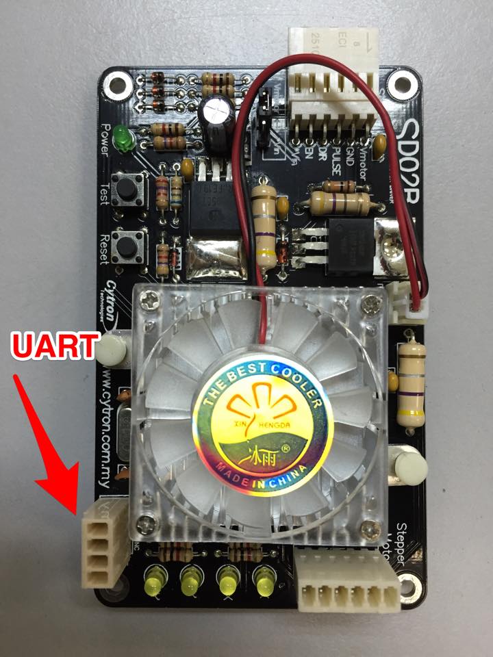
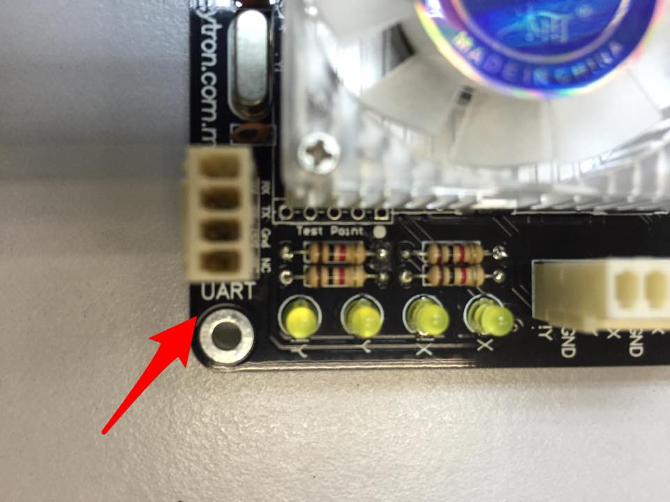
So basically, I have a Bordreuil stepper driver that has a UART port. Now, in order for me to the engine with LABVIEW interface, I have to connect the motor via the driver via the UART port for the right to acquisition of data? So my question is basically how can I do this? Is there are special cables? If so, can you guys please paste some links that could help me choose one. If not, then please help me to find a solution to this. I need to get this project done in a week.
In addition, if you know the guys from any tutorials where I can easily learn how to set up a regulator PID on LABVIEW and also code my control algorithm (if that is even possible in LABVIEW) Please paste these links tutorial here too.
Appreciate the help. And God bless.
Peace.
Maybe you are looking for
-
Satellite A660-1DW - adapter in the box?
Hi newbie here. It is perhaps the most incredibly stupid question on here but anyway. I bought a 1DW A660 Argos today and get it home, unpacked the portable, but seem to have only the power cord with the standard bog 3 pins taken end, wrong thinking
-
Windows xp - printing option only record
using windows xp and google chrome - recently by selecting one option is to save or cancel printing. I just want to print.
-
Unable to connect to the main DNS server when you try to access the internet
Computer has worked fine for the year last until 2 weeks ago and now unable to connect to the internet. Windows Vista on broadband and services connected directly to the modem by ethernet. Provider Internet has run tests and confirmed modem is fine
-
removal of unidentified network
How can I remove unidentified network which shows on my network and sharing?
-
Unknown symbol of Smartphones blackBerry BB tour
I noticed a new symbol on my phone that I've never seen elsewhere. Can someone help me understand what it is? Looks like a yellow ledge "Hangman" (upside down letter "L") with a red circle inside. I also noticed when I tap on BBM my screen keeps flic