UART to DAQ
Hello
I'm new to LABVIEW, and I am currently working on my final year project.
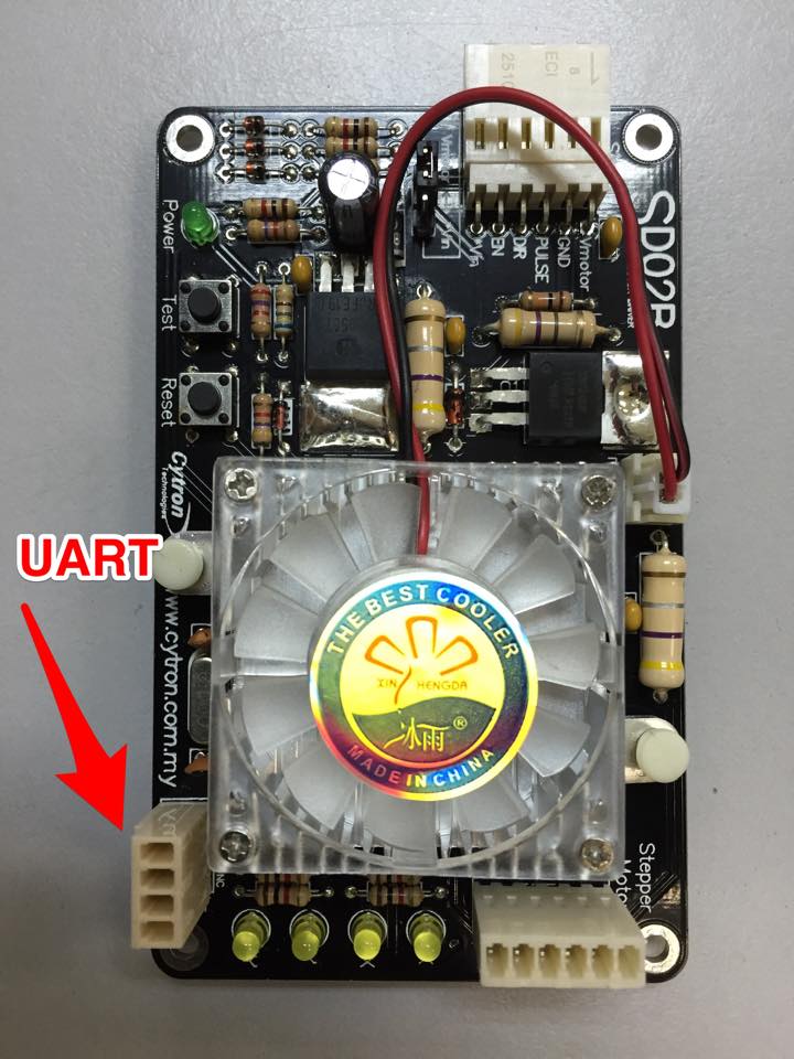
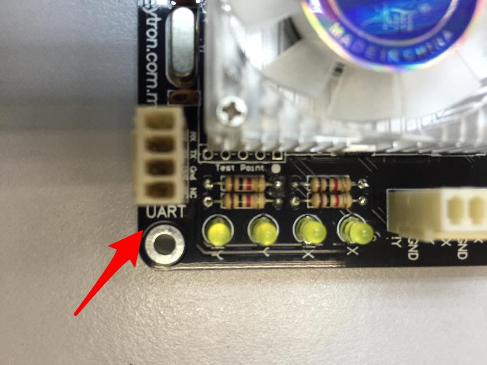
So basically, I have a Bordreuil stepper driver that has a UART port. Now, in order for me to the engine with LABVIEW interface, I have to connect the motor via the driver via the UART port for the right to acquisition of data? So my question is basically how can I do this? Is there are special cables? If so, can you guys please paste some links that could help me choose one. If not, then please help me to find a solution to this. I need to get this project done in a week.
In addition, if you know the guys from any tutorials where I can easily learn how to set up a regulator PID on LABVIEW and also code my control algorithm (if that is even possible in LABVIEW) Please paste these links tutorial here too.
Appreciate the help. And God bless.
Peace.
Tags: NI Software
Similar Questions
-
DAQ Assistant is not in LabView
Hi all
I use NEITHER cDAQ-9174 and NI 9203. I have already installed the driver for the NI 9174 cDAQ, which is NEITHER-DAQmx 9.8.0. I can see the device when I opened NI MAX. However, when I open LabView 2015, I can't find DAQ Assistant in the function Palette. I noticed on the chassis, 'ACTIVE' light is not on while two other "POWER" and "READY" light is on. I look in the forums OR but I can not find the solution.
Any suggestion, please help!
Thank you!
DAQmx 9.8 is not compatible with LabVIEW 2015. You must use at least DAQmx 15.0. See here for more details: NOR-DAQmx and LabVIEW compatibility
-
Card NI DAQ for SinCos encoder?
We have a RON285 heidenhain encoder that uses signaliing 1Vpp for "infinite precision". Essentially, it generates two differentials Sin / Cos signals angle and the phase between them allows you to achieve extreme precision for the angle of the encoder. You must always send two signals with a comparator hysteresis to essentially convert the signal quadrature encoder and count the pulses. Calculation of phase angle gives you the fractional precision.
(1) no matter who never used a capture card of data OR to read in the first tensions and make the calculations necessary to convert the singal SinCos until a high precision angle? If so, you are ready to share the code?
(2) make the SinCos--> Quadrature conversion on the card itself by splitting off the two singals SinCos in two other channels and specify these two channels is coded quadrature singals or do have external hardware do the comparator + hysteresis before it captures in the map?
P. S.
I just found this piece of hardware that does exactly what I described in #2 above, I get this same functionality using just the DAQ itself card? http://www.motrona.com/SinCos.html
The pointed inline Heidenhain WHAT JB interpolator is exactly the kind of thing I used other suppliers. Yes, you can introduce digital quadrature channels in a meter and other synchronization maps DAQ in a PXI chassis. 9 kHz in quadrature frequency is easily manipulated by the jury.
Setting the "pulses per rev' to 360000 and choosing degrees for units should cause the task to do the math for you, for example, when you call DAQmx Read values should already be adjusted to degrees. Personally, I do always some reason check this scaling value to make sure that there is not a factor of 4 gap because of the differing terminology between encoder and DAQmx tasks sheets.
As to limit yourself to the Tween 20 x, I tend to agree. If the Encoder error has been distributed randomly, I completely agree. But because much of it is probably more systematic than at random, there is a * chance * as some other fractional resolution might be useful. Probably a pretty small gain at best however. Unless it's quite similar cost & time probably, I wouldn't bother to > 20 x.
-Kevin P
-
I'm looking at the SMU 7857R. I would use the 8 analog inputs and the FPGA to do some annalysisy and DIO based on the best data. I was wondering if it is possible to also define a DAQ task so that all analog data will be made available to the host. Using a data acquisition task would be easier for me to have to write code fpga for use a DMA fifo to send back data.
Hi bcat!
A data acquisition task is only for devices Data Acquisition product supported by driver DAQmx as X-, M-, S-, maps E-Series. The boards of the R series are only supported by the driver OR RIO.
If you don't need pre-treatment on the FPGA so that you can distribute simple data through DMA on your host. If you are looking for an API for the comparable FPGA with the DAQmx API then please check the NI CompactRIO waveform reference library. You can also use the library for R Series boards. -
Buen dia could sugerirme como could reduce el código al leer multiple Líneas y canales of DAQ, on the imagen como dejo una are lo hago currently. Saludos
Hola buenos dias lancelot2610,
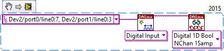
MUCHAS gracias por comunicarte con nosotros a los foros ayuda, training in the Quebec you can reduce el código're colocando multiple ports in the same selection of the las líneas como entrada is muestra in este example:
Formation of seleccionarlos're a traves del click derecho y con opcion browse para con seleccionar multiple puertos con sus respectivas líneas en salida lo Québec obtendras're el arreglo results of forma lineal in this case have concatenados results of todos los puertos tal y como los placed the entrada en.
Otra forma are creating a task from which MAX contenga ports that need, aqui you annex United Nations procedure, este're para señales analogicas pero regardless of the misma forma seleccionando las digital señales:
http://digital.NI.com/public.nsf/allkb/F28C6BD62B0ED68F86257A6B00733E0E?OpenDocument
Espero y esta information you sea utility,
Saludos,
CaEnOs
-
Panel Test DAQ opened on the remote system
Using the command-line tool nidmfpan.exe you open a test panel to a device on your system by specifying its name. Here is an article which he described.
http://digital.NI.com/public.nsf/allkb/9B628A8B1B13136F86256DDB0004DE4D
But what is not mentioned is how to call this function if it will open a panel of test on a RT system. This is possible because in MAX, you can select the hardware and the same test panel is displayed, but I don't know the right way to call this EXE, so it will open it. Is there any place that command line switches are documented for this program? And what is the method for opening a panel of test on a piece of DAQ hardware on a remote system? Thank you.
Since nobody has been able to help me I thought about it myself. If you call the application nidmfpan.exe with the command line switch send_break_action: with the IP address of the remote system it works great. I also found you can use the/dev: instead of the /devid: to specify the device by a unique identifier instead of the alias MAX. Thus, for example:
C:\Windows\SysWOW64\nidmfpan.exe /host:192.168.129.1/dev: {84535FB2-8F2A-11E6-8061-00802F25AF78}
Or
C:\Windows\SysWOW64\nidmfpan.exe /host:192.168.129.1 /devid:cDAQ1Mod2
-
frequency DAQ USB issue (6211)
Hello
I'm a newbie when it comes to NOR and data acquisition. I bought a NI USB 6211 and connected a resolver with 400 Hz and ai1, ai2 (CSR) (sine and cosine signals). I also have the reference of the power supply connected to ai3 (differential) of signals. Pockets of tension give a +/-2.5 Volts from all sources input signal.
The problem is that the signal moves to the right. She moves uniformly for all signals.
Now, I wonder is it possible to synchronize the input signal so that it moves? or what I need to resolve this issue programmatically? I'm programming in C with standard DAQmx drivers (v15.1). But I saw the same problem with Labview and Measurement Studio.
Thanks in advance for your suggestions.
Kind regards
Gerhard
I guess I just find the answer to my question here:
http://forums.NI.com/T5/LabVIEW/DAQ-Assistant-can-t-lock-the-signals/m-p/1332484#M542285
I guess I have to ask in the forum section of C++ for an example of a software lock.
Kind regards
Gerhard
-
I use the outgoing/incoming analog DDK with the DAQ 6341 SMU map.
The examples, for example aoex5, show a single timer (method outTimerHelper::loadUI), but the example shows the DMA loaded with same size of vector data.
There is a comment in the outTimerHelper:
 call rogramUpdateCount, which implies that memory sizes different pad per channel can be used.
(the comment is: switching between the sizes of the various buffers is not used)
Nobody knows what should be the format the DMA buffer for data from multiple channels with different frequencies?
For example, we want a0 with a sinusoid at 1 kHz and a1 with a sine wave of 1.5 Khz. What looks like the DMA buffer?
With the same frequency for each channel, the data are interleaved, for example (ao0 #0, ao1 #0; ao0 ao1 #1, #1,...), but when the frequencies for each channel is different, what the stamp looks like?
Hello Kenstern,
Data are always intertwined since each card has only a single timing for each subsystem engine.
To AO, you must specify the number of samples that will be released to the AO. You also specify the number of channels. Because he didn't is that a single engine timing for AO, each AO will be channel will be updated at the same time to update clock tick. Data will be interlaced exactly as shown in the example because each channel AO needs output at each tick of the clock to update. The data itself can change depending on the frequency you want to copy.
kenstern wrote:
For example, we want a0 with a sinusoid at 1 kHz and a1 with a sine wave of 1.5 Khz. What looks like the DMA buffer?
With the same frequency for each channel, the data are interleaved, for example (ao0 #0, ao1 #0; ao0 ao1 #1, #1,...), but when the frequencies for each channel is different, what the stamp looks like?
In your example, you must come with an update rate that works for the two waveforms (sine waves of 1 and 1.5 KHz). To get a good representation of a sine wave, you need to update more than 10 x faster than your fastest frequency... I would recommend x 100 if possible.
Update frequency: 150 KHz
Channels: 2
Then create you stamps that include complete cycles of each wave you want to produce based on the frequency of update. These buffers must also be of the same size.
Buffer 1: Contains data for the sine wave of 1 KHz, 300 points 2 cycles of sine wave
Buffer 2: Contains data for the sine wave of 1.5 KHz, 300 points, 3 cycles of sine wave
You can Interleave them as before. When the data are performed through the ADC, they are out different sine waves, even if the AO channels are updated at the same speed.
-
Why is-DAQ-200714 fatal error?
I'm having a problem where a system that works well for a while, with a good margin (rate of 1 kHz loop, 300uS PCL loop duration), suddenly throws the error-200714 and stops. I have the filter DAQ errors on, and it's performance that are linked, so why this closure of the system rather than increment on behalf of HP?
Thank you
The explanation of the error is "Acquisition has stopped because the driver could not transfer the data from the device to the computer's memory rather quickly. This was due to limitations of the computer system.
Reduce your sample clock rate, the number of channels in the task or the number of programs on your computer that runs at the same time. »
Hello Stephen,
You get this error is because the program is not keeping up with the sample clock.
I recreated this (outdoor VeriStand) by running the example of shipping single HW-Timed Point LabVIEW and increasing speed until I got this error. I actually got error-209802 several times before to do-200714. The first error is recoverable and I could ignore it and continue, the second execution stops when it is thrown.
Error-209802:
«DAQmx wait the next sample clock detected one or more examples missed clock of the device since the last call to wait for the next sample clock that indicates that your program is not keeping up with the sample clock.»
To remove this error, slow down the sample clock, or else modify your application so that it can follow the sample clock. Alternatively, consider conversion errors affecting true property warnings and then assigned to the case of the appropriate warning. »
Error-200714:
"The acquisition has stopped because the driver could not transfer the data from the device to the computer's memory rather quickly. This was due to limitations of the computer system.
Reduce your sample clock rate, the number of channels in the task or the number of programs on your computer that runs at the same time. »
Based on what Jarrod mentioned above, the original error might be filtered by VeriStand judging by the part highlighted in blue to the first error. I suspect that the error-200714 is fatal because of the part highlighted in red above; the acquisition has ceased.
If you monitor the DAQ system channel error, you see error-209802 so? Slow down the rate PCL resolve these errors?
I hope this helps!
Trent
-
Error-200284 when using two daq cards
I have an application written in Visual C++ that reads data out of a data capture with success card. However, now we want to add a second DAQ card, so we can increase the number of input channels. However, I have trouble getting the second card works fine. He continues to give the 200284 whenever I try to read the input data. I tried playing with the two loops in the same thread and with them in threads separated without result. Any ideas on what could happen?
Thank you!
Hello Kaladin,
I'll take a look at the link below to see the cause of the error, but also some common things suggested to try.
http://digital.NI.com/public.nsf/allkb/FEF778AD990D5BD886256DD700770103
Best wishes!
-
Where are the UART pins on sbRIO-9627?
I'm new to the SingleBoard RIO and I need 5 UARTS, but I can't find RX TX PIN. Where the pins are located?
Data sheet: http://www.ni.com/pdf/manuals/375466a.pdf
Product page: http://www.ni.com/white-paper/52801/en/
RS232
Edge (Total) = 2 (6)Page 42 of the manual to the user began documenting how to expose additional UARTS.
http://www.NI.com/PDF/manuals/375466a.PDF
The UARTS are implemented in the FPGA, so the TX and RX pins can be routed to the FPGA DIO lines. Which is defined via the sbRIO generator tool CLIP installed with LabVIEW and implemented by selected a half TON plugin CLIP in the LabVIEW project.
Page 24 of the RMC design guide also gives more details:
http://www.NI.com/PDF/manuals/375536a.PDF
In addition, this presentation of NIWeek walks through the design process RMC and SW tools for configuration of devices, such as the UARTS.
https://decibel.NI.com/content/docs/doc-43347
Kind regards
-
201003-error occurred in the DAQ Assistant
Hello. I use "cDAQ-9178" and "NI 9215" and "NEITHER 9402" are added on. "
However, when I run Labview code, "Error-201003" occurs.
{
Device not available. Possible causes:
Device is no longer present in the system / device is not powered.
Device is turned on, but was temporarily without electricity / device is damaged
}
(Error appears as the 1st and 2nd figures below).
(Plans of logic is the figure below).
Thank you.
I could be something with the pilot
Check this box:
Error 201003 to the MAX test panel or all by running the DAQ Assistant
http://digital.NI.com/public.nsf/allkb/5413F392D88326148625746B006745C5
In this forum, they speak the same error:
Spontaneous error code 201003 for acquisition of data PCI configuration
http://forums.NI.com/T5/SignalExpress/spontaneous-error-code-201003-for-PCI-DAQ-Setup/TD-p/830707
-
Hello.. I use usb 6353 DAQ board for my project. I want to buy 3 different voltages and post it on labview. When I take a channel (ai0) data in the daq assistant it works fine, but when I add channels (ai1, ai2) in the nd task run it, tensions mix. I used split Subvi to separate dynamic data, but the readings are all wrong.
What I am doing wrong?If you see ghosts?
-
Neither daq 6009 - delay in time between the measures
Hi all
My first post
 I have a small question about the acquisition of data with the NOR-DAQ 6009, where I try to get one or more number of samples per minute. Let's say I want to wait for some time before taking a measurement. I don't know how to do this. I tried to figure it out by myself, but because I am completely new to LabView and I come from the OR-6009, I was wondering if someone can help me here.
If this is useful, I enclose the .vi.
Please let me know if you need more info.
Thanks in advance.
You would get the timestamp before the average like I said or just call to get Date/time according to the seconds. Example below. You can recreate a waveform data type or do whatever you want with the timestamp and the average.

-
Hey everybody,
I have a stepper motor wich work good with "control engine daq-stepper (constant speed).
My problem is the constant speed.
I need to change the speed during the motion, and I don't know how to do this.
Thanks for the help and sorry for my bad English!
Hello
With the example of a constant speed at all times generate you a PWM with a cycle of constant use.
To change the speed you'll have to play with the duty cycle.
To do this, you can take a llok at the following example:
How can I change the use on my continuous pulse Train?
Kind regards
Maybe you are looking for
-
no idea how to tell firefox that .qfx files should start quicken 2007?
Firefox 3.6.3 (Mac) knows only .ofx Quicken files. I don't find any obvious way to add. QFX to the list and the dialog box ('open with this application', always "do it in the future) hasno effect. huh? This has happened Each time Firefox opened Is th
-
Hello I am designing a table of basic with some features. In the VI below, I have a table with four columns 2d and four lines. I want the table to display the first line first on an indicator on the front panel. Then for the 2nd it would show upside
-
I can't install most of the system disk c.It programs always show me "system cannot find the path specified." But, when I copy it to a disk D it starts installing. Most of the programs is not installed properly, because it seems that they cannot acce
-
I have a picture on my c: drive. how he do it in my project. I have robohelp 2015
I have a picture on my c: drive. how he do it in my project. I have robohelp 2015
-
I have Acrobat standard 9 in my pc. Now the company system work the Terminal display.
How can I install it again one when?