Replacement of simulate signal VI with the DAQ assistant
Hello
I have a VI fucntioning, where signal comes 2 simulate VI signals and is being recorded.
I replaced that with the DAQ assistant. I want to know if the wiring is correct and if it will give me the same result as the simulated VI.
Thank you.
Hello Andy,
Thanks for the reply, yes I did that as well, another way to do it is the 'split signal VI' that automatically separates the signal into 2 channels, most of the high sons being Ch 0
S
Tags: NI Software
Similar Questions
-
Simulate signals wired to the DAQ assistant for USB-6009 device
Hello
I'm trying to send a signal to the DAQ Assistant Express VI. I watched the movie "Generating a Signal" on the Web site of NOR (www.ni.com/academic/students/learnlabview/generate.htm) and I have my Signal simulate connected directly on the DAQ Assistant, as shown in this film. In my case, the DAQ Assistant sends the signal to a device USB-6009.
However, I received this message:
Error-200077 occurred to the DAQ Assistant
Possible reasons:Requested value is not supported for this property value. The value of the property may be invalid because it is in conflict with another property.
Property: SampTimingType
asked the value: Sample clock
You select: On-demandIf I select 'On Demand' in my DAQ assistant and run the vi everything works beautifully. However, I need my DAQ assistant to be configured to generate a waveform AC continuous, not output a single alternating current rippling.
What happens here? I did not have this problem before on other devices of NOR. I am using LABView 2010.
Please answer.
Thank you.
-
Hi all
This should be a pretty simple question, but I can't seem to find the answer online and currently do not have the functionality to test this:
I'm using LabVIEW 8.5 and have a VI that imports data from sensor through the DAQ Assistant. In the configuration tab, there is a range of signal input. What happens if my sensor exceeds this range? I get a warning? The default value is the maximum (or minimum)? I was interested in writing a code to display an error that I approach the limits of this range, but did not know if I also need to include code to display an error if the scope is exceeded as well.
Thanks for the help,
Tristan
Hello, Tristan,.
The behavior depends on the selected range and the device you are using.
If you are using a device with a single input range is valid, we will use this range, even if you set a smaller minimum and maximum in the DAQ Assistant. So, if your device only supports ±10V and you set the range to ±8V, you will still continue to get valid data after your top sensor 8V until what you approach 10V. When you reach the limit of the extent of your device, the output will be 'rail', and simply return the maximum value until the signal is less than the maximum value again.
Note: A device that is nominally ±10V usually has a go-around (such as ±10.2V) which are usually specced in the manual.
However, if you use a device with several ranges of entry then things become more complex.
NOR-DAQmx player will choose the smallest range that entirely covers the interval you choose. For example, suppose that your device supports the following input range: ±0.2V, ±1, ±5V, ±10V and you choose 0V - 3V as the range in the DAQ assistant. The NOR-DAQmx driver will focus on the input range and the list of the entry lines that your hardware supports and choose the smallest encompassing the entire range that you set. This would be the ±5V, because this is the only beach that contains up to 3V. Thus, all between ±5V input signal is returned and none outside this range will be 'rail' to the maximum or minimum value.
We do this because using small beaches make more efficient use of the resolution of the ADC. So, we try to use the most effective range based on what you ask without picking up a range that will make you miss data.
Let me know if I can clarify it more.
-
Calendar and the problems of data collection with the DAQ Assistant
Hello NOR Developer area,
I am a Novice of LabVIEW and have seen how helpful you all can be, and if I come to ask for your help.
I'm having some trouble with a VI I built that specifies an input voltage, a SCB - 100 connected to a PCI-6031E and converts this tension in a temperature displayed on a waveform table. The goal is to give a constant reading of the temperature and display it in a chart for as long that the VI is running (and to reset the chart the next time the tracks of VI).
The problems I've encountered currently are:
-After a few minutes of the VI running, I get an error message 200279: tried to read samples that are no longer available. The requested sample was already available, but has since been replaced. (to the DAQ Assistant express VI).
-I don't know how to change my chart so that the minimum value X is both during which the VI was launched and have the maximum X value increases with each iteration of the loop. Currently, I have the VI get the time system and contributing to the property node X scale. This worked for the graph of the voltage, but not for the temperature chart
I appreciate those of you who took the time to read my post.
Thank you all for your help.
Sincerely,
Ethan A. Klein
SB candidate in Chemistry & Physics
Massachusetts Institute of Technology
Class of 2015
PS I enclose my VI to give you a better understanding of my current situation.
E A Klein wrote:
Thanks for writing.
What property node is talking?
I do not understand that many different data types. How can I go on the treatment of all the data?(Did you mean I should wire 'blue' data for mathematical functions rather than using the node property tension?)
Sincerely,
In fact, one of the nodes property. I mean specifically the tension property node. But in reviewing, I noticed the other nodes in property for the chart. Just set auto-scaling to the X scale and that should take care of two of the nodes property (right click on the graph, X scale-> AutoScale X Scale). I also recommend placing your mathematical functions in a Subvi to make things easier to read. Attached, that's what I think you're after.
I hope that these small tweaks will speed things up enough to avoid your error. If this isn't the case, then we should begin to look at the design of producer/consumer model or take readings at the same time. It might also be worth looking away the DAQ Assistant and DAQmx real screws. But one step at a time.
-
New Daq with the Daq Assistant in the filtering code
Hei,
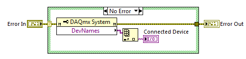
I have a NI USB-6225 DaqMx I used a couple of years. When I started with LabVIEW, I found the Daq Assistant to the best way to measure the voltage with my Daq etc. My company has purchased another DaqMx NI USB-6225 and now I have a big problem: the Daq Assistant in my old Vi does not work with the new data acquisition. I understand why there is this problem, but I do not know how to solve. I found this code on the forum who finds that Daq is connected:
The problem is that Daq Assistant do not have an entry for it, and it gives me an error if I try to run the code with a different device than the original, I used when I created the code.
Is there a way to solve this, so I don't have to convert all the Assistants Daq normal code?
Hello again,
two options:
(1) as the old software is related to 'Dev1' you must rename your new device to this alias and skip/rename the old device (and lack).
(2) rewrite your old software does not become is not dependent on the name of the alias for the data acquisition card...
It's your choice!
-
Number of events with the DAQ Assistant, offered PFI0, offered Ctr0. Samething?
DAQ USB DAQ Assistant 6009. I plugged a PFI0 (port 29) push button switch and + 5V (port 31). Setup Assistant DAQ ==> Acquire ==> meter entry ==> edge ==> Dev1(USB-6009) - Ctr0 counter ==> a sample on request.
I was offered the Ctr0 and not PFI0 (port 29) selection, so I chose Ctr0. Samething? Will this work with how I wired to the top of my switch?
I count 'digital highs', so wire to 5V and sprayed. Right?
With LV2013 and an acquisition of data connected to the computer, you can do what I did in a vi project and/or a regular, standard vi. Right?
Thank you for your time
dunnor
Hoovahh
My hard wire solution worked will PFI0 and GND. Sorry. I thought I could go back and give congratulations after I tried things. I would like to press the buttons now, but I don't see them.
dunnor
-
How to create a task in the DAQ Assistant of LabView for one of our modules cDAQ without actually being connected to the cDAQ module?
You can simulate a large number of instrument supported by DAQmx with Measurement & Automation Explorer.
Right-click on the NOR-DAQmx devices and then create new, then simulate and choose from the list of supported devices.
For the cDAQ chassis first then your module.
Excuse me, but I don't have an English version of MAX and so I did not have the correct translation of command...
When your simulated device is configured, ca use you it with the DAQ Assistant in LabVIEW.
-
No device supported in the DAQ assistant
Hi all
I use the scanner high speed (NI 5922). I installed Labview 8.5.1, then the software scope OR the digitizer NI 5922 high of speed, then the hardware driver. I tested the DAQmx with the MAX and it passes the test. But when I started to use the labview with the DAQ assistant, as described in the manuals I have not found all devices supported! Should I log a physical device to the hardware driver channels or what should I do?
Thank you
Ibrahim
The 5922 is supported by NO-Scope http://www.ni.com/digitizers/software.htm and not by DAQmx. This page should help you get started.
-
Hello, this is my first post here,
I've been wondering about this:
When you configure a new daq with the daq Assistant, is the resolution applied to the voltage / number of entries you define, or is it a fixed value per volt by channel.
For example:
I have a 6015 usb data acquisition, it has 16 inputs analog, 16-bit resolution 250 kech. / s 09:50 volts.
so is this as (2 ^ 16) / (16 * (-10-10)) = my resolution through volt?
or that this has nothing to do with the amount of channels,
If I want to measure more than 0 to 5 volts, my 16-bit apply from 0 to 5, or even more scale of data acquisition (which is 09:50 volts)
Thank you
Marco
You will get full-resolution 16 bits on each channel regardless of the number of channels is configured. Renault most are multi-plexed if your specification of sampling RATE in usually a global significance that you can only scan channels with a sampling frequency = MAX RATE / number of CHANNELS. Also, most NI Renault have a Programmable Gain amplifier on the front-end server, so if you specify a range of voltage smaller in your task configuration the amplifier will automatically increase the gain to use most of the possible BIT ADC. You see care device and for more details...
-
There is no entries or exits on the DAQ assistant to connect to
Hello world
I'm new to labview and have encountered difficulties with the DAQ assistant. I'm under v8.0, v8.7.1 OR-DAQmx labview and have an acquisition data PCI-6224 installed. It seems that every time I have let down the DAQ assistant (assistant of the instrument and data acquisition simulated has the same question) on the block diagram and configure it, it don't y no input or output that I can wire a control or an indiactor to. Y at - there a step I'm missing somewhere?
Thanks in advance!
Try to repair the DAQmx driver through control panels and see if that solved the problem.
How to uninstall or repair OR software?
http://digital.NI.com/public.nsf/allkb/AC6ED75D3D93375686256E8E00245F0D
-
Error to the element of the queue with simulated signal, but not with the DAQ hardware
Hello. I get an error code 1 when I run my VI in simulation mode, which is only 3 simulate subvis signal at different frequencies. The block diagram shows jpg file and the probe is after I stop the VI. Note that there is an invalid refnum. I don't know why that is. I am also including the watch of the probe after a few iterations, there is no error on the probe 64 until I stop the VI, and also noted that there have been no queue items. This of course means that I don't get to remove the data in loop 2. An interesting note is that the system works fine when I run the program in data acquisition mode, which is the other case behind the 'simulate signals. " In this case, the only thing is the DAQ assistant and dynamic data of the tunnel cable. Everyone can't see what I could do wrong? Thank you.
Thanks for looking at my post. I thought about it about five minutes ago. I didn't have a timeout on the handeler event, so it was not double check for new items in the queue. I don't know yet why the probe shows showes that items have not put in the queue because they certainly were. Maybe "queue items 0" means that there are no items saved in the queue. ?
Your concern is interesting and deserves a check... I just ran it without registration, and it seems that the release of the case (the default) record structure is just an empty DDT, a placeholder, I guess.
-
Is the DAQ Assistant compatible with LabView7?
I am equipped with a LabView7 and a NI DAQ - 6015 Pad and am trying to monitor the temperature with two thermocouples. I searched some tutorials online, but most suggest using assistant DAQ, which is not listed in the section of my functions palette entry. I have downloaded the NOR-most recent DAQmx driver who is supposed to be compatible with LabView 7.x. I don't know if this means that it is compatible with LabView 7.0. I still do not see the DAQ assistant appear.
Any help or suggestion (about DAQ assistant or how to program in LabView7 to solve my problem) is greatly appreciated!
Thank you.
It looks like the DAQmx latest version is 8.1 which will work with LV 7.0
See here http://digital.ni.com/public.nsf/allkb/97D574BB1D1EEC918625708100596848
-
I would like to replace my drive 160gig hard with the disk hard 320gig on my laptop running xp.
I would like to replace my drive 160gig hard with the disk hard 320gig on my laptop running xp. Is it possible to transfer the exact content from one disk to another without having to re - install operating systems and programs etc. ? I would that all is the same except the size of your hard drive will be increased.
Is it possible to transfer the exact content from one disk to another without having to re - install operating systems and programs etc. ?
Yes.
You use the disk cloning software. In some cases, a new player may even be bundled with software that will do this for you.
Unless your laptop has a second drive Bay (most don't), you will also need an external hard drive enclosure. As a general rule, these connect via the USB port, although if your laptop has a connector FireWire or eSATA you can also use these interfaces.
You must select your external enclosure based on 3 criteria: the type of connection to the laptop. the physical size of the disc (2 1/2 inches for computer laptop drives); and player interface (determined by the connection of the internal drive of your laptop). For example only (no recommendation), if you wanted an enclosure for a 2.5 IDE drive "which connects using USB 2.0, Newegg has 17 products
The (slightly) more expensive items among the software, you will need. For example: http://www.newegg.com/Product/Product.aspx?Item=N82E16817155602 this particular House will work with SATA or IDE drives.
If you buy an external enclosure that doesn't include cloning software, the software may be available for free from the manufacturer of the new 320 GB drive (e.g., http://support.wdc.com/product/downloaddetail.asp?swid=119) or you can get it separately (this is not an exhaustive list):
Acronis True Image Home 11
EASEUS ToDo Backup
Paragon Drive Copy or Partition Manager Personal -
Precise triggering voltage input and output generation in the DAQ Assistant
Hello
I wonder if anyone has come across a simular problem with the synchronization of input and output voltage. I use a box 11 LabView and NI USB-6259. I have been using the DAQ Assistant to configure the input and output channel. In particular, my task is to generate a single rectangular "pulse" as the output voltage to drive a coil and once the pulse went to get a signal from a sensor of magnetic field and get a power spectrum. This means that the order and the time during which the DAQ Assistant is used is extremely important. For example, the output voltage channel must be opened first for 2 seconds. Subsequently, the channel of input voltage must be open for 1 second, in which the sensor signal is obtained and post-processed. Only after these tasks are performed in this order he can can be repeated in a loop until the experiment is over. I don't know how to trigger data acquisition assistants (one for entry) and the other for the voltage output correctly. Y at - it a trick?
See you soon
Michael
Hi Dave,.
Thank you that I wired the error strings but the timing issue was unrelated to it. In the DAQ assistant, I simply had to choose the continuous aquistion of the 'samples' methods 'N-switch' for input and output voltage and all works fine now.
Thanks again
Michael
-
Hello
Another noob to join the community. Here's my question.
What I am doing wrong? I use 2 assistants for the acquisition of data on the module of NI9401 for output and input digital. I use it to generate signals of 2. If I test with 1 it works but if I go to 2 or more it fails. This is the error I get. I also added the program as an attachment.
Thanks in advance.
Hello
This error means that the DIO task is reserved and cannot be obtained by one of the DAQ Assistant. There is actually a program example on what you want to do. It can be found here:
https://decibel.NI.com/content/docs/doc-11632
This example does not use the DAQ Assistasnt but the DAQmx API screws, (which use the DAQ Assistant also still). If the order is not important (and since these DIO tasks are software timed this probably isn't a problem, you can also choose to use the cluster of error one DAQ assistant and connect to another see annex VI.) Do this way force you a data acquisition task to wait on the other a finish. In this way, they don't run to preventing it from time even for the error to occur.
Kind regards
Maybe you are looking for
-
My Mac mini smaller base model is really slow
It's so boring and when my Mac is really bad, it freezes and won't pass the mouse and this Mac is not old, it was purchased, form the Apple Store last Christmas. It's terrible and this Mac costs £399.00 and may not seem much to some people but it def
-
How to remove the "another Memory" Macintosh HD?
Hello So, I was see a gradual increase in the size of the 'other' memory of the Macintosh HD in the system that I use. A return of the week available space was 50 GB. Now, he has reduced to 30 GB. I use not all mobile devices to attach to this system
-
try to install GEFORCE GTX650 in my HP Pavilion p6 - 2413 has but the display will not illuminate.
Try to install the GEFORCE GTX650 in my HP Pavilion p6 - 2413a, I plugged everything in and the fan seems to work but the display does not illuminate. There is another cable with 2 multi 1 6 end plug but I can't work out where to connect. I tried to
-
I recently bought a HP6520 and I am now configuring the efax account, however, when I go to the link of the HP software Efax, the "Create A New Account" button is grayed out (not adjustable). Please let me know how to apply for efax and get the fax
-
How do I enabled the requirement that requires a password at startup after a reboot
I'm looking for the command string that allows you to set a password that will be used someone restarts the computer.