reverse hexagonal signal
Hello!
I use a DB9 contact and re232 to communicate with a device, the device needs a five byte long signal in hexadecimal (2 a 00 55 1582). However, when I send the signal by using labVIEW it gets reversed. I ' v tried to the inverse by my selfe but without success. I'm ading a photo on my signal (top) and the right to one (at the bottom) and you can is it should also be high idel. How can I return my signal in LabVIEW?
It really looks like you are comparing apples and oranges. The background signal is not a valid RS-232 signal. The voltage levels are all wrong. If your old device sends this, you'll have to do a translation at the level of the serial port of the pc on the output. There is nothing that can be done in software. The UART of the pc is responsible for the voltage levels and they are correct.
Tags: NI Software
Similar Questions
-
Pxi different 2-5421 or-tclk synchronization help and reversing a signal
I have 2 PXI-5421 function generators. Screened through my vi I load a .hws file and output the same signal makers 2 all in phase and triggering the same point. I need basically to do, it is reverse one signal of 180 degrees and keep them always trigger the same starting point.
im not sure how is invert the signal on a 5421 or how to separate code so that each signal generator is separated.
Hi Liam,
I did a quick search on your issue and I think it is interesting to try to 'configure exit Mode.vi niFgen' (red border on the screenshot) and the value
output mode of entry to the "arbitrary signals" (right click on the parameter "Output Mode"-> create constant-> select 'arbitrary signals' in the drop-down list).
You could include a code of the error you found in your next reply. Thank you!
All the best,
-
How to reverse 'Ongoing Acquisition' - Signal (Pike F421B)
Hello everyone,
I am currently working on a machine to control tree cam using the Pike F421B. Before I used the Smartview AVT software. Now my company wants to change for LabVIEW, because we have developed our own analysis program. During the image acquisition process exits camera has "occupied" - signal. My question is: is it possible to invert this signal somehow. I was able to reverse in AVT Smartview but I can't seem to find settings in LabVIEW. This signal is used to trigger LEDs sequentially so that the acquisition of the lighting and the image is synchronized. The problem is the LED controller reacts to the front down a trigger. That's why I need to somehow reverse that signal without external wiring. I currently use the VI "vision acquisition." I would be grateful for any solution. (See also photo).
Thank you.
I assume you mean that the camera came out of this signal by means of a line of input/output, correct? You should probably use some access to the registry to configure this. If you check the manual of your device it should list the records, you must configure and you can then use the registry read/write IMAQdx screws to access.
Another option would be to use an AVT software and save the default settings of this I/O reversal signal in slot voltage by default the camera. Since it is not affected by default IMAQdx framework is broad, it should keep this charged setting even after IMAQdx substitutes parameters with what you saved the VI or MAX Express software.
Eric
-
Hello!!
I'm trying to built a small radar with the USRP 2920...
but I have a problem.
I connect the two ports of the USRP (TX1-RX2) with a cable with low loss of 50 cm...
after transmission of a chirp signal, sometimes I found my IDE oucederomsurlesecondport rx staggered 180 degrees... totally opposite signal
It is possible, it is a problem of the LNA on the USRP?.
Francesco
PS
I had this problem too with the USRP of Ettus 1
The RX and TX share a 10 MHZ reference, but not their respecive derived from local oscillators. This means that the derived LO clocks can lock at different phase shifts that will change every time that the application is executed, but remains at a constant offset (coherent) during the race.
-
Hello
I searched for a VI to solve what seems to be a pretty simple (and common) problem but I can't seem to be able to find all messages about this and I spent almost half yesterday on this.
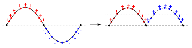
Basically, I would like to convert the wave of negative polarity in positive i.e. to get the absolute amplitude.
Maybe it's better explained visually:
Can someone kindly tell me the good VI which can do the job?
Any help would be greatly appreciated.
Take a look at the building of the "absolute value" in the palette of digital features. It seems to work on the sinewave waveform palette.
-
Convert uint8 hexagonal table in reverse order double, uint16, channel, etc
I get back an array of uint8 size 4 from a buffer that happens to what follows:
C4 e5 d7 (hexadecimal) ed
and need to convert it so that it reads:
d7e5edc4 (hex)
3622170052 (decimal)
I know it can be done in a loop using some<'s or="" something. ="" i="" can't="" remember="" all="" this="" low="" level="" stuff="" so="" help="" would="" be="" greatly="" appreciated. ="" i="" can="" rearrange="" the="" initial="" data="" array,="" but="" not="" sure="" how="" to="" convert="" to="" decimal="" number. ="" i="" assume="" a="" simple="" for="" loop="" starting="" at="" the="" end="" would="" be="" the="" easiest="" way="" to="">
PS on this subject, where is a good place which explains all the uses of < or=""> > or ^ = etc.
Thank you
I happened to use this routine in the past to accomplish a task like yours:
string to unsigned char [5];
int number;
String [0] = 0xc4;
String [1] = 0xed;
String [2] = 0xe5;
String [3] = 0xd7;
String [4] = 0x0; string terminator
number = (string) conv_dword_to_int;
int conv_dword_to_int (unsigned char * buf)
{
Return ((*(buf + 3))< 24) ="">
((* (buf + 2))< 16) ="">
((*(buf + 1))< 8)="">
((* buf + 0));
} -
Why the extreme to express signal is broken
I have an Airport Extreme b, g, n, ac cable (ethernet) to my router Verizon Wireless. The router has been updated by Verizon end of last year and works very well. From there, I have an iMac with 802.11 b/g/n/ac cable into the extreme as well. I have a Windows pc in another room wired with ethernet to the extreme as well.
At the back of my house, I have an Airport Express b/g/n I used to extend my Airport Extreme signal for the past 18 months without any problem. I had problems of signal with the Express and it seems to re-defining the Express worked, but the image of my signal has changed my Airport utility on my iMac. Previously, the signal was solid from the far down to the Express, and the image on my iPhone 6, at the launch of my Airport utility has been broken from the extreme to the Express.
Now the images are reversed where my iPhone has the solid signal, and my iMac broke the line signal. Someone knows why? It works, but the lines threw me.

A dotted line between the terminal of the AirPort Express and AirPort Extreme indicates that the Express connects to the extreme by using a wireless connection.
What do you want?... or... the Express linking to the extreme by using a wired Ethernet cable connection? If If this is the case, there should be a continuous line between the Express and Extreme.
What device do you have used when you reset and reconfigured the Express... the iMac or the iPhone?
Did you completely turn off the iPhone, has waited a minute or two and then he fed up and checked the AirPort utility again this way?
-
Lenovo E440 microphones reversed? I think that the left and right are wrong
Hi, I have E440 i5 8 GB Windows 10 to date and version of driver Conexant 20751 SmartAudio HD 8.66.16.50. I clicked on "update driver" and came to is that it is the most recent version.
In the settings of the card, I enabled 'hear this device' and position normal when you look at the screen and your hands on the keyboard, if you type the right hole mic I can hear the left audio channel and vice versa for the left. Is this normal? Try with your laptop. I mean, it would be nice if you want to record something with the laptop back on what you want to record, but I think that most of the people in the land would the laptop screen making in the face of what they want to record, especially if they're going to use the camera and video.
Looked at google but nothing came
Add: I noticed in the properties: configuration of the Microphone, in the 'Options' tab advanced, there in the background 'Improve the Signal' and a checkbox "Enable sound improvements" WHICH I ALWAYS turn OFF and the sound quality is crisp, clear and loud, but the pickups are reversed, now if I select this check box, the sound is really bad miserable, for 256 Kbps 32 Kbps and its going to MONO. Any permeable I scratch, sound comes from the Center, so I would REALLY like that this "activate sound improvements" disabled people, hands down. PD: This option is not even reduce any type of noise, I know it's what he is for, I can still hear my strikes and miners of sounds equally with it enab/disab.
Another thing is: it not "Conexant Audio Setup GUI" nowhere to be seen, I have looked everywhere in the PC, this audio driver just doesn't does not with any audio different installation "Dolby" read and option on the 'enable strengthening its' in the record.
OK, updated, I thought I had won the battle, well, almost, rebooted again and reinstalled my pc the * beep * driver CONEXANT, but found another solution, followed this tutorial
https://blogs.msdn.Microsoft.com/matthew_van_eerde/2010/08/23/troubleshooting-how-to-install-the-MIC...
And recovered the "pilot High Definition" and I think that this time it will stay.
One thing I noticed that the volume icon in the lower right missing, check list "hide icons" and "Volume", it turned on, I am appearing at this time, may try another reboot. -
HP110-210: intermittent loss of signal
Constantly, I lose my signal (wired) internet. The average loss time is around 9-10 seconds, then resumes signal and continues on the site, I asked. I have a router TP-Link AC1750 which I contacted and after a week of troubleshooting, they determined that this isn't their router. Likewise, they went through all my setting the adapter too. I have PC(HP also) then one more and there is no problem of the internet. If you look at the pic below () screen, I loose connection can it resume. I have the latest drivers. I tried to reverse the ports of the router and change the cables... Any thoughts?
I was told by support for the operating system is corrupt and they will send me a new OS. It's to bad I have to pay for it, because the computer is 12 days old only... but that's what it is, I guess.
-
BUG: Split then join reverse byte order - sometimes
I created a simple to serialize an array of bytes I32 and fell VI on this interesting bug. This code runs in 32-bit SP1 of LabVIEW in 2014, fully patched. Save the parts two attached and run TestI32ToByteArray.vi. Note that the 6 and 7 at the end of the table are reversed. If you explore the data around, everything looks good except the string split on the last low word is reversed. Any ideas?
More details on the installation program:
LabVIEW 2014 SP1 32-bit
AMD FX - 6300 3.5 GHz processor hexagonal
Windows 7 64 - bit, fully patched
8 GB RAM
Check your wiring, 6 is connected to a lower bound of the join, and 7 is wired to the top.
-
I need to output a low frequency signal (between 2 and 30 Hz) between the output of a sound card at the entrance of another sound card, between two PC. Sound cards is not designed for frequencies below 30 Hz. That's why I need to use the Modulation of frequency or AM, (or PCM) on the outlet side to create a signal, for example, between 102 and 130Hz. How can I accurately demodulate the signal so I can treat it as the original 2 Hz to 30 Hz signal in my journal? I think since DASYLab support the AM, FM and PCM that it would also support the process reverses. How would I do that?
Although I wasn't able to demodulate the signal, using the FFT, I was able to isolate quickly the frequency since my entry was a pure sinusoidal signal.
Thanks to CJ to work up to an earlier example that brings me down the path to implement the solution!
-
Hello
I have a signal and you want to measure the phase and ampl. I m try three different methods, i.e. Discrete Fourier Transform (I just calculate myself, according to the formula), Fast Fourier retrieves only your information (using the sub - vi nickel) and all give same range but different phase. Can someone take a look at my sample program and help me figure out what is wrong.
Thank you
Take a look at the attached (version 8.0). All the approaches came up with the same value after you have made the following changes.
1 FFT - off "unpack phase" so reading is included between - pi and pi.
2 DFT - deny the imaginary part (I found equations show the imaginary part reversed)
3. single signal - subtract 90 degrees out of phase
4 Multi tone - subtract 90 degrees out of phase
Of course, if you do not deny the imaginary part of the DFT, and the DFT, simple tone Multi tone all pretty well corresponds with the FFT being shifted 90 degrees. I can't tell you why this is so. Maybe guys CAN shed some light on the differences. I hope this helps.
-
How to subtract one signal on the other, with the help of an oscilloscope?
I have two chaotic oscillators, which I am trying to sync. There is an oscilloscope, which channels are related to each oscillator. I need remove the signal from the oscillator-B, the oscillator signal - A, using the oscilloscope, so that I can find how much is the error between them. A - B would work very well, but there is only A + b. is it possible to do, without having to add additional circuit elements? If this isn't the case, that I would add, subtract one signal from another?
Edit: I use the classic Multisim 13.0 oscilloscope.
Hello.
You can invert the signal B-
the standard scope 2 ch a reversal for Channel B - there are 4 small buttons on the bottom of the chB instead of only 3 for chA.
Best regards
Michael
-
Align the two signals and measure the Phase Shift
Hello
I do an experiment in which I use the NI USB-6221 DAQ card. The jury is able to make 250 k samples/second. I want to measure two voltages in a circuit and find the phase shift between them at frequencies between 1 and 10000. First I ouputted a wave sinusoidal frequency variable through the Commission and applied to a test circuit. Then I used the Board to measure the two tensions consecutively (thus reducing the maximum sampling frequency at 125 k). I used the signals align VI and measured the two phases and then calculates the phase shift (VI attached in Phase 1). It worked well for the test circuit I built in which the phase shift went way logarithmique.20 degrees ~84.5 degrees and then stabilized. At frequencies above 5 000 Hz phase shift must have remained constant, but it varies more or less 1 degree. When the phase shift is 84.5 degrees, present a degree of variability is not particularly explicit. When I asked my program on the circuit that I really wanted to measure, the phase shift went from-. 5 degrees up to about 1.2 degrees. The change in the values of phase shift at high frequencies (> 3000) was environ.2 degrees. Given the small phase shift, this variation is unacceptable. Now I tried to use a sequence to each blood individually (increase the maximum sampling frequency to 250 k) and then align the two signals and measure the phase of each shift. When I use align it and re - sample Express VI to realign the two signals, I get the message "error 20333 analysis: cannot align two waveforms with dt even if their samples are not clocked in phase." Is it possible to align two signals I describe here? I enclose the new VI as Phase 2
Matthew,
I think I have an idea for at least part of the problem.
I took your program data and deleted stuff DAQ. I have converted the Signal on the chart control and looked then what was going on with the signal analysis.
The output of the Waveforms.vi line has two waveforms, like the entry. However, arrays of Y in the two waveforms are empty! It does not generate an error. After some head scratching, reading the help files and try things out, that's what I think is happening: the time t0 two input signals are 1,031 seconds apart. Since the wavefoms contains 1,000 seconds of data, there is no overlap and may not align them.
I changed the t0 on two waveforms are the same, and it lines up. The number of items in the tables is reduced by one. Then I increased the t0 of 0.1 seconds on the first element. The output had both greater than the entry by dt t0 t0 and the size of the arrays was 224998. Reversing the t0 two elements shifts the phase in the opposite direction.
What that tells me, is that you can not reliably align two waveforms which do not overlap.
I suggest that you go to 2-channel data acquisition and that it accept the reduced sample rate. You won't get the resolution you want, but you should be able to tell if something important happens.
You may be able to improve the equivalent resolution by taking multiple steps with a slight phase shift. This is similar to the way that old oscilloscopes of sampling (analog) worked. Take a series of measures with the signal you are currently using. The make enough average to minimize changes due to noise. Then pass the phase of the signal of excitement to an amount that is smaller than the resolution of phase of sampling rate and repeat the measurements. Recall that I calculated that for a 5 kHz signal sampled at 125kHz, you get a sample every 14.4 degrees. If shift you the phase of 1 degree (to the point/mathematical simulation), you get a different set of samples for excitement. They are always separated by 14.4 degrees. Take another series of measures. Transfer phase another degree and repeat. As long as your sampling clocks are stable enough so that frequency does not drift significantly (and it shouldn't with your equipment), you should be able to get near resolution of what you need. The trade-off is that you need to perform more measurements and may need to keep track of the phase shifts between the various measures.
Lynn
-
Question about reversal of pin of the PXI-6562
I have a PXI-6562 card with cable which is the note.
Note If you create a customized with connector wiring solution (779157 - 01) and cable (192744-01), the NI 656 x pinout is reversed at the level of the end fitting. For example, the signal on pin 1 on the previous figure would map to pin 73 at the level of the end fitting.
Pin 1 go back to pin 73, but what about the pairs?
Pin 2 return to 71 or 72?
1 - 73
2 - 72
.....
73 - 1
All pin codes signals add up to 74


Maybe you are looking for
-
Hello. last update of the IOS on
Hello. yesterday updated the IOS on my iphone 6 s and all my music disappeared
-
Problem with heat on initialize to top with Satellite M40
Hello group, I have a question, when my laptop Satellite M40 warm up and I tried to restart the display changes to 2/3 and lock-up. Then I have to press the power button to stop the process and expect that the laptop cools a bit. I have them push the
-
Pencil can be used to select items and/or double-click iPad Pro?
Pencil allows you to click or double-click on iPad Pro w / iOS 9.1 and higher?
-
Using XP, how can I move bookmarks on the desktop
I want more of my favorites on the desktop items. How to do his? Dave MH
-
Failure of signature blackBerry RRT fot key Code registration
Hello I got all three keys to RIM, and I have registar key ' client - RBB-* .csi "and" customer - CPR-* .csi "but when I try to sign the" customer - RRT-* .csi ' key I get this error:"Registration failed because ID customer * is not configured to be