Reversing a temporal signal
Hello
I searched for a VI to solve what seems to be a pretty simple (and common) problem but I can't seem to be able to find all messages about this and I spent almost half yesterday on this.
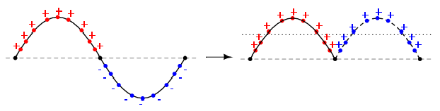
Basically, I would like to convert the wave of negative polarity in positive i.e. to get the absolute amplitude.
Maybe it's better explained visually:
Can someone kindly tell me the good VI which can do the job?
Any help would be greatly appreciated.
Take a look at the building of the "absolute value" in the palette of digital features. It seems to work on the sinewave waveform palette.
Tags: NI Software
Similar Questions
-
How to reverse 'Ongoing Acquisition' - Signal (Pike F421B)
Hello everyone,
I am currently working on a machine to control tree cam using the Pike F421B. Before I used the Smartview AVT software. Now my company wants to change for LabVIEW, because we have developed our own analysis program. During the image acquisition process exits camera has "occupied" - signal. My question is: is it possible to invert this signal somehow. I was able to reverse in AVT Smartview but I can't seem to find settings in LabVIEW. This signal is used to trigger LEDs sequentially so that the acquisition of the lighting and the image is synchronized. The problem is the LED controller reacts to the front down a trigger. That's why I need to somehow reverse that signal without external wiring. I currently use the VI "vision acquisition." I would be grateful for any solution. (See also photo).
Thank you.
I assume you mean that the camera came out of this signal by means of a line of input/output, correct? You should probably use some access to the registry to configure this. If you check the manual of your device it should list the records, you must configure and you can then use the registry read/write IMAQdx screws to access.
Another option would be to use an AVT software and save the default settings of this I/O reversal signal in slot voltage by default the camera. Since it is not affected by default IMAQdx framework is broad, it should keep this charged setting even after IMAQdx substitutes parameters with what you saved the VI or MAX Express software.
Eric
-
Hello, I am designing a detector of negative edge using a d-type flip flop that gets a signal from two cascaded from the binary counters that are used to reset when the desired value is reached. The design should include a frequency of window, but I do not know how to implement it. I tried to implement but I could, but I don't know if it works. No idea?
Hello, thanks for the answer
Sorry, but I guess I'm not smart enough to digest your description.
I have-
We must build counter for 0.51 with reset - you did.
We must build flipflop (FF) with triggers on falling edge.
the possible solutions are-
-You can use rising edge FF if you could reverse the trigger signal.
Learn about the different types of FF, some of them work on edges falling
with it will be useful
Good luckMichael
-
Questions about the frequency step response
Hello
I use the Signal Express 3.0. I'm not clear on the transfer functions in step of frequency response with different modes of calculation of the average. What I got from the help file is this H (f) = Sab (f) /Saa (f) which is cross the frequencies on the spectrum auto where is the pulse and b the signal response signal. When the mean quadratic value is used, I wonder if the transfer function becomes greatness of cross spectrum divided by the magnitude of the spectrum of the car. When an average of vector is, everthing is used in complex numbers. He averaged temporal signals, frequency domain signals, or the results of transfer functions?
Thank you very much.
The algorithm to calculate the spectrum is the same in both modes. However, the method of calculation of the average can have a huge impact on the outcome. Mean quadratic value is performed on the spectrum itself, after the calculation. Vector averaging is done on the input signals before the calculation. With an average of vector signals must be consistent (have the same phase) or the result will be bad due to the signal being on average by far.
-
Lack of charges, USB-6211 with linear gauge Mitutoyo (542 series)
I use a USB-6211 box with a race of 10mm Mitutoyo Linear Gage (542 series, model LGA-110). The Mitutoyo has output similar to an encoder without the time by rev signal quadrature. (B has a phase shift of 90 degrees of A). Signals A and B are airline pilots. I have a k 2 5V to A resistance and another 2K to 5V to B, gives me a minimum of 0.05v and a maximum of 4.75V.
The problem I encounter is that I seem to be missing certain counts that I can't always zero.
I found that if I caress the complete range of meter and the return to zero in 20 seconds, I get a value close to 180 meter microphone. If I press the complete range of meter and the return to zero quickly in a second, I get a value close to 800 micrometer.
If I caress the quick pledge on the compression and rebound more slowly, I find myself with a positive value. I caress the slow pledge on compression and quick on the rebound, I find myself with a negative value.
As I said before, it seems miss me certain counts. With a pulse of each mic of 4 meters, it means I get only 2500 pulses per 10mm. This means that 10mm per second is only 2500 pulses per second. It seems slow for me, so I don't know what would be the problem.
Does anyone have ideas for me to try?
With this type of signal you should not missing any counts. The time base on the box USB-6211 is 80 Mhz and therefore should have no problem to solve your two pulses per train. I have a couple of steps that I would like you to try troubleshooting.
1 to ensure that we plugged the inputs correctly to our DAQ hardware.
2 ensures that we use both the non-reversed or two signals reversed. Do NOT mix or 'type' of the signal.
3 allows you to wire signals A and B in two inputs analog and we will try to read signals to ensure that the sensor is actually be set correctly by the sensor. Be sure to taste pretty quickly--> 10 the frequency of the pulse train. If you race through 10 mm in 1 sec--> 2500 pulses per second--> 25 kHz sampling rate. Allows to check two things. First we have a good TTL signals, and that we get the right number of charges. If you reply to this thread plaese attach a screenshot of the present.
4. we will try different encoder types x 1, x 2, x 4 in the DAQ assistant. The x 2 and x 4 encoder allows the best sensitivity for small movements (which I'm not sure that it is the source of your proplem but it will be a good thing to check). Types of encoder are discussed in more detail in the following developer area: quadrature encoder measures: How To?
Let us know how it shapes to the top.
-
Best way to make this step motor control system
The goal of my project is to have real-time data collected by a controller of Sir 158u Dataq a stepper motor. I grappler planned on executing it with the basic stamp, but I realize that's not possible. I have a stepper motor and a L293DNE driver. I'll be permanently registration of data with the dataq, the form of volts and want these values to determine how the engine works. For example, if the voltage is 0-3 volts, I want it running clockwise, 3-5 volts not turns not, and 5-8 Volt turn clockwise.
I tried to understand this last week, searching through discussions with basic stamp, matlab and labview now.
Is there an easy way to do this? or easier way that I'm trying to understand?
Any help would be greatly appreciated!
Thanks in advance.
-Nick
Nick,
What I was describing, this is how you configure the motor controller to accept PWM of LabVIEW and mode locked anti-phase so you can control the direction of the motor. Much on the part of LabVIEW depends on the acquisition of data you use. For example the acquisition of your data doesn't have a counter which can generate a PWM? I did some checking everything on time and the acquisition of your data is not made by National Instruments and I couldn't locate the native LabVIEW drivers. I did however go to the MFG Dataq 158u site and found that they do not have drivers LabVIEW BUT their software (SW) should run in the background. Dataq 158u website also has a help forum, I suggest you start to understand the capacity of the 158u Dataq. Also it seems that you are not familiar with LabVIEW, until you can take on a project like this, you have to start with the LabVIEW Basics, learn how to manage the tables so you can store your results of EDA and records the use of loops and timing and movement. NOR has a basic training FREE as the intrudction 6hr to LabVIEW, I would like to start their. Oh, and in your OP (original post) you doubted the Basic Stamp could do that, I do this type of control using the Atmel microcontrollers all the time, I'm sure that the stamp eaisily could do. Download right on one of their forums for more information. Oh and to answer your question a UPS is an IC that reverses the input signal, which you would end upward with the direction of you pines motor controller is PWM on a spindle and 180Deg off phase PWM, on the other hand.
Alan
-
Hello
Could someone help me on how to split/split signals into a bus several outings? I have conversion Demux of Matlab but have difficulty to use in LabVIEW. Maybe someone knows how to use in LabVIEW or any other method that could achieve the same thing as Demux.
Example, I got 10 signals on a bus and I wanted to divide for different outputs 5 where the first release contained 4 signals, 2 outputs contained 3 signals and the rest contained 1 signals.
Signals could be anything, constant or any temporal signal.
Thank you
Search for Unbundle in Labview, it will solve your problem...

-
Pxi different 2-5421 or-tclk synchronization help and reversing a signal
I have 2 PXI-5421 function generators. Screened through my vi I load a .hws file and output the same signal makers 2 all in phase and triggering the same point. I need basically to do, it is reverse one signal of 180 degrees and keep them always trigger the same starting point.
im not sure how is invert the signal on a 5421 or how to separate code so that each signal generator is separated.
Hi Liam,
I did a quick search on your issue and I think it is interesting to try to 'configure exit Mode.vi niFgen' (red border on the screenshot) and the value
output mode of entry to the "arbitrary signals" (right click on the parameter "Output Mode"-> create constant-> select 'arbitrary signals' in the drop-down list).
You could include a code of the error you found in your next reply. Thank you!
All the best,
-
Hello!
I use a DB9 contact and re232 to communicate with a device, the device needs a five byte long signal in hexadecimal (2 a 00 55 1582). However, when I send the signal by using labVIEW it gets reversed. I ' v tried to the inverse by my selfe but without success. I'm ading a photo on my signal (top) and the right to one (at the bottom) and you can is it should also be high idel. How can I return my signal in LabVIEW?
It really looks like you are comparing apples and oranges. The background signal is not a valid RS-232 signal. The voltage levels are all wrong. If your old device sends this, you'll have to do a translation at the level of the serial port of the pc on the output. There is nothing that can be done in software. The UART of the pc is responsible for the voltage levels and they are correct.
-
Hello!!
I'm trying to built a small radar with the USRP 2920...
but I have a problem.
I connect the two ports of the USRP (TX1-RX2) with a cable with low loss of 50 cm...
after transmission of a chirp signal, sometimes I found my IDE oucederomsurlesecondport rx staggered 180 degrees... totally opposite signal
It is possible, it is a problem of the LNA on the USRP?.
Francesco
PS
I had this problem too with the USRP of Ettus 1
The RX and TX share a 10 MHZ reference, but not their respecive derived from local oscillators. This means that the derived LO clocks can lock at different phase shifts that will change every time that the application is executed, but remains at a constant offset (coherent) during the race.
-
Why the extreme to express signal is broken
I have an Airport Extreme b, g, n, ac cable (ethernet) to my router Verizon Wireless. The router has been updated by Verizon end of last year and works very well. From there, I have an iMac with 802.11 b/g/n/ac cable into the extreme as well. I have a Windows pc in another room wired with ethernet to the extreme as well.
At the back of my house, I have an Airport Express b/g/n I used to extend my Airport Extreme signal for the past 18 months without any problem. I had problems of signal with the Express and it seems to re-defining the Express worked, but the image of my signal has changed my Airport utility on my iMac. Previously, the signal was solid from the far down to the Express, and the image on my iPhone 6, at the launch of my Airport utility has been broken from the extreme to the Express.
Now the images are reversed where my iPhone has the solid signal, and my iMac broke the line signal. Someone knows why? It works, but the lines threw me.

A dotted line between the terminal of the AirPort Express and AirPort Extreme indicates that the Express connects to the extreme by using a wireless connection.
What do you want?... or... the Express linking to the extreme by using a wired Ethernet cable connection? If If this is the case, there should be a continuous line between the Express and Extreme.
What device do you have used when you reset and reconfigured the Express... the iMac or the iPhone?
Did you completely turn off the iPhone, has waited a minute or two and then he fed up and checked the AirPort utility again this way?
-
Lenovo E440 microphones reversed? I think that the left and right are wrong
Hi, I have E440 i5 8 GB Windows 10 to date and version of driver Conexant 20751 SmartAudio HD 8.66.16.50. I clicked on "update driver" and came to is that it is the most recent version.
In the settings of the card, I enabled 'hear this device' and position normal when you look at the screen and your hands on the keyboard, if you type the right hole mic I can hear the left audio channel and vice versa for the left. Is this normal? Try with your laptop. I mean, it would be nice if you want to record something with the laptop back on what you want to record, but I think that most of the people in the land would the laptop screen making in the face of what they want to record, especially if they're going to use the camera and video.
Looked at google but nothing came
Add: I noticed in the properties: configuration of the Microphone, in the 'Options' tab advanced, there in the background 'Improve the Signal' and a checkbox "Enable sound improvements" WHICH I ALWAYS turn OFF and the sound quality is crisp, clear and loud, but the pickups are reversed, now if I select this check box, the sound is really bad miserable, for 256 Kbps 32 Kbps and its going to MONO. Any permeable I scratch, sound comes from the Center, so I would REALLY like that this "activate sound improvements" disabled people, hands down. PD: This option is not even reduce any type of noise, I know it's what he is for, I can still hear my strikes and miners of sounds equally with it enab/disab.
Another thing is: it not "Conexant Audio Setup GUI" nowhere to be seen, I have looked everywhere in the PC, this audio driver just doesn't does not with any audio different installation "Dolby" read and option on the 'enable strengthening its' in the record.
OK, updated, I thought I had won the battle, well, almost, rebooted again and reinstalled my pc the * beep * driver CONEXANT, but found another solution, followed this tutorial
https://blogs.msdn.Microsoft.com/matthew_van_eerde/2010/08/23/troubleshooting-how-to-install-the-MIC...
And recovered the "pilot High Definition" and I think that this time it will stay.
One thing I noticed that the volume icon in the lower right missing, check list "hide icons" and "Volume", it turned on, I am appearing at this time, may try another reboot. -
HP110-210: intermittent loss of signal
Constantly, I lose my signal (wired) internet. The average loss time is around 9-10 seconds, then resumes signal and continues on the site, I asked. I have a router TP-Link AC1750 which I contacted and after a week of troubleshooting, they determined that this isn't their router. Likewise, they went through all my setting the adapter too. I have PC(HP also) then one more and there is no problem of the internet. If you look at the pic below () screen, I loose connection can it resume. I have the latest drivers. I tried to reverse the ports of the router and change the cables... Any thoughts?
I was told by support for the operating system is corrupt and they will send me a new OS. It's to bad I have to pay for it, because the computer is 12 days old only... but that's what it is, I guess.
-
Example of signals with a filter anti-aliasing
I use PCI-6259 6221 PCI and USB 6221 cards in different configurations. As I understand it, is that the anti-aliasing filter on all of these cards is fixed to pass to the frequencies of 1 MHz. If I'm a signal from a RG58U BNC cable that is supposed to contain higher frequency of 1 kHz sampling, but there is noise of high frequency present there. A sampling of the signal to 2 kHz would be enough to acquire the signal correctly, or these high frequencies would affect the components of low frequency on sampling?
I read about too much sampling that allows you to use digital filters (I'm guessing that software filter can be used) If you sample the data at a higher rate. You should always use the anti-aliasing filter, but the required parameters are more relaxed. Would this work in my case? The anti-aliasing filter on my cards has a very high bandwidth, so I don't know how much I need to do to acquire the signal correctly oversampling. Is there an equation?
Also, if the analog inputs for data acquisition cards are generated by a filter (for example when recording ECG or EEG) which allows you to specify a bandwidth frequency, I still need a filter anti-aliasing? Would be the distance between the amplifier and the DAQ card much a difference when it comes to the generation of noise on the cable?
In general, I try just to see if my current collection method at the rate of Nyquish with the maps I have is good or not. I just save the data without even using any digital filtering (software).
That's right - if you go down to 10kS/s then the temporal resolution and minimum pulse detection would 100us. If it is a just sampling rate or not depends on your requirements for the accuracy of timing and jitter. In other words, if it's OK that your pulse Detection could could delay until 100us then a 10kS/s sampling frequency should be OK.
-
I need to output a low frequency signal (between 2 and 30 Hz) between the output of a sound card at the entrance of another sound card, between two PC. Sound cards is not designed for frequencies below 30 Hz. That's why I need to use the Modulation of frequency or AM, (or PCM) on the outlet side to create a signal, for example, between 102 and 130Hz. How can I accurately demodulate the signal so I can treat it as the original 2 Hz to 30 Hz signal in my journal? I think since DASYLab support the AM, FM and PCM that it would also support the process reverses. How would I do that?
Although I wasn't able to demodulate the signal, using the FFT, I was able to isolate quickly the frequency since my entry was a pure sinusoidal signal.
Thanks to CJ to work up to an earlier example that brings me down the path to implement the solution!


Maybe you are looking for
-
changed to 8.0 and now my keyboard shortcuts cut paste don't work
Yesterday, I downloaded the new version of Firefox (8,0) and now my copy / paste keyboard shortcuts do not work, i.e. Ctrl C and Ctrl V. I searched the help section and found that someone had this problem with an earlier version. They mentioned that
-
XP problem constant errors and the loss of the Im... Reformats multiple
Well after a long time to use my computer * the bed... He said that the Config/System file is missing or damaged was told to fix. So after about 10 formats later and the error comes constantly with 1 million other mistakes so many different blue scre
-
whenever I boot windows, a Trojan horse is here. the antivirus (windows essential) picks it up, asking to clean, and does. Unfortunately, every time I start the computer, the Trojan horse appears upward. I did the full analysis, cleaned the horse
-
When I go to computer management console and click on Task Scheduler, a box appears and says"(blah blah blah depending on the task) task"cannot end as the image of the task has been altered or falsified"it says this for EACH scheduled task. If I clic
-
Windows Media Player configuration parameters may be wrong:
Windows Media Player configuration parameters may be wrong: This quick message I hurt get the WMP from my computer, sounds are distorted, why is it so?