Signal conditioning equipment
Hello
I need to measure the frequency of several input (from 1 to 200 k) signals with 6024E PCI DAQ cards. What signal conditoning hardware I need for this the simplest and cheapest way? IE: convert the frequency of a voltage
Thank you
Curt
A few notes:
-6024E PCI data acquisition max sampling rate is 200 kech. / s, aggregate. This means that this clock frequency is shared between all channels. If you use a single channel of entry by card, you could reach 200 kech. / s/channel, but if you use two channels, this will be divided up to 100 kech. / s/channel. This is described in the E-Series user manual.
-C' is relevant because even at a rate of 200 kech. / s, you can only reliable collect information on the frequency of signals slower than 100 kHz according to Nyquist. For the faster cards, see the M Series DAQ.
Tags: NI Hardware
Similar Questions
-
Can I use with NI PCI-6233 of SCXI signal conditioning
The title says it all. I wonder if I can use my unit with the NI PCI-6233 industrial data acquisition card and if so what cable should I use between the chassi and map of SCXI signal conditioning?
Hello Tsthorsell,
This feature is not plausible. This can also be verified by simulating the chassis and unity, the 6233 OR cannot be selected as the transmitter/receiver.
Best regards
M Ali
Technical sales engineer
National Instruments
-
Activation with M-series USB-6289 on-board signal conditioning
I currently use the series M-6289 to monitor a few analog voltages. I noticed that she has integrated signal conditioning hardware. How to enable and configure this upward? Is it through S/W or H/W?
V/r,
Chris
Hi Chris,
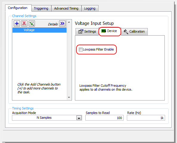
Are you talking about low-pass filter 40 kHz programmable? Here's how to activate it via the API: Filter Programmable on the M-series cards
Or with the DAQ Assistant:
Brad
-
NEITHER USB 4432 readable voltage i.e. the ASPM signal conditioning
Hello
For what I understood that the USB-4432 entries must read IEPE accelerometers report. Read a voltage signal conditioner of my sensor ASPM IE using the option 'IEPE-off with AC coupling.
Thank you
1. What if I use the 5th cahannel of
4432 read the square wave pulse width, i.e. the digital signal
tachometer using any function of sounds or labview software and
Vibration Measurement Suite. If so, how precis specific will be read
frequency (speed) compared to meter modules.Channel 5 is the same as the other channels of the 4432 except it lacks excitement IEPE and TEDS. I can't really say how "accurate", it will be at a faster rate because of the delta-sigma ADC. Someone else wants to chime in on this one?
2.
Is available to trigger analog acquisition of digital triggering. If so, is
It possibel to read all 5 channels togather in a single task.You're talking about!
3.
If there is only one PFI then is possible to trigger two
different tasks, i.e. a task of 02 strings with front amount and
a further task of 02 channels with the falling edge of the PFI even.There are 8 PFI lines, but can only be used on the device at the same time (it might as well be one PFI). You must have all the channels you want to raise in a task and use one as the trigger for starting digital PFI lines. (i.e. 'no'
 ... have a stain on the front and the other on the falling edge won't work, a task only by digital triggering)
Germano-
-
conditioning of signals using RTD
I want to know on how we will design the circuit of signal conditioning for RTD... using 3op - amp instrumentation amplifier... If know something about it so please tell me... as soon as possible...
I like to draw circuits like this, although it is almost always cheaper to buy an amplifier for instrumentation of TI or announcement that in order to pay me to do.
You can ask specific questions we don't need to guess what you want?
Lynn
-
The dual SSID Signal interference
I have the cable and Internet provided by AT & T. I mainly had Comcast when you live in different parts of the country. I am owner of an Airport Extreme and Time Capsule I used previously to set up the network internal in addition to the SSID broadcast material of the cable company. I never had a problem before using AT & T. I noticed that the Internet speeds both the provider of cable and speed on the internal network have been seriously degraded. I was unable to stream movies. After several attempts to solve the problems with AT & T and myself, I found the problem: it seems to be interference of signals between AT & T and Airport Extreme material each broadcasting separate SSID in very close to one another. I got the Apple hardware, and the problem was solved immediately. While I'm happy to have it fixed, I don't miss the advantage of having the internal network using Apple devices. What are my options? Is it correct that I can't use the Apple devices to extend the SSID signal emissions equipment AT & T? I think the problem might be solved, perhaps, if the two gateways were not close to one another, but I do not have another spot to plug the Airport Extreme.
Is it correct that I can't use the Apple devices to extend the SSID signal emissions equipment AT & T?
Unfortunately correct.
Apple routers work that to extend another router from Apple... no other brand is invited to the party.
I think the problem might be solved, perhaps, if the two gateways were not close to one another, but I do not have another spot to plug the Airport Extreme.
Separate the two routers as much as you can... I always recommend 6feet or about 2 M. If they are closer than this really a wireless should be turned off. Only for this case deactivate the ATT router instead of your apple.
There are enough wireless channels to run 3 wireless routers close to each other.
Sometimes the automatic separation of channels does not work and you need to get and change physically.
Use wireless diagnostics (many versions available, but it is built into Mac OS since the Mountain Lion)
There are a bunch of tools... the actual diagnosis is not particularly useful in my experience.

Open scan.

You will need to click on it to see the whole thing.
Now, I have a few questions... first, I'm not showing noise... This is just my configuration problem. But you should see RSSI (signal level), noise, channel, band, width and country.
Watch channels... My installation has some problems because most of the 2.4 ghz is using channel 11.
The diagnosis tells you even what channels to use.

I can open airport utility and select one of the units in issue. Click the icon from the airport... Click on edit in the preview.

Go to the wireless tab.

Click Wireless options

Change the automatic 2.4 ghz regardless of the channel you want.

Save and update from the airport.
Especially for 5 GHz, I think that your stay on auto should be fine. It is more short-range and isn't usually a big problem.
Note also the signal strength really counts... things go wrong if you don't have enough separation and the signal strength is low.
2.4 GHz, there are only 3 channels Alcan... 1, 6, 11
Although Diagnostics of scanning you will offer between channels... do not be fooled that this corrects the problem.
Read the wiki for wireless lan.
https://en.Wikipedia.org/wiki/List_of_WLAN_channels
Channel 6 for example is actually peak signal to 6, but it covers 4 to 8.
-
example of blocking software signal in C++
Hello
I am new to the NC and data acquisition. Just posted this question before http://forums.ni.com/t5/Signal-Conditioning/usb-6211-DAQ-frequency-question/td-p/3202422and discovered that the signal cannot be locked on a hardware level.
Can anyone provide an example in C / C++ to lock a 400 hz signal. I used the example of ContAcq - IntClk.c to read the data of a resolver (Sindh and cosine) and a reference signal. However as the signal moves to the right (in this case) it becomes difficult to determine the position of the resolver.
Thank you in advance.
Kind regards
Gerhard
Looks that I itself can solve another of my posts
 solitaire here in this forum... sort of...
Well, since I asked for an example of code, I'll give my solution here. This is probably by far not perfect, but it works. Suggestions for improvement are welcome.
DAQmxErrChk (DAQmxReadAnalogF64 (taskHandle, 1000, 10.0, DAQmx_Val_GroupByChannel, data, 3000, & read, NULL));
If (read > 0) {}
< 2999;="">
{
If (data [loopa] > highestRef)
{
highestRef = data [loopa];
highestPos = loopa;
}
}
References = data [highestPos];
continue = data [highestPos-1999];
cosine = data [highestPos-999];radians = atan2 (cosine, continue);
angle = radians * (180 / M_PI);<>
angle += 360;printf ("D: %f %f Ref: %f refH: %f Pos: %i angle: %f\r", continue, references, highestRef, highestPos, cosine and angle);
fflush (stdout);
} -
Large signal output capacitance measurements
Hi all
I'm working on a power amplifier and I want to measure the ability to output under large signal condition. I use a non-linear model of the GaN power transistor.
Power output is about 36 dBm, f = 8.2 GHz
I tried both methods:
(1) I have spent under bias Vgs - 6V to 1V, Vds = 28V. I use solver C_PRC linear tab to find the parallel to the output capacity. I got a chart that changes from 0.3pF to 0.5pF. In this simulation I don't use tuner to impedance, just ports (50 ohm) and sources of bias.
(2) amplifier is biased to 28V and 125mA. Then, I drive amplifier with of 20dBm to 30dBm input power. In this simulation, I used HBTUNERs to maximum power output (power input 25dBm at the entrance) and the output. I can see there is a change in capacity at the entrance vs input power change. However, in the output, production capacity is constant and 0.52pF. I am able the ability of the drain of transistors, tuner. I use great Solver for the parameter measuring signal Y and calculate the capacity.The interesting thing, I can meause entry changes easly to large signal capacity, but output capacity is constant!
I have two questions:(1) why the three measures are different?
(2) for large signal measurements, for example; 30dBm output, 30 v peak-to-peak output average 40dBm 50 v peak-to-peak. So, there is a change in capacity over a period of time. When I measure the Solver big signal, Solver uses the high peak values? If so, can I change low peak value?
(3) can be used for important signals gamma probes?
Thank you
-
Accelerometer (voltage) of the signals using the module NI6361 (PXI)
Hi guys,.
I posted this question once again, but I still have problems with the acquisition of data. I'm acquiring a voltage signal by using an accelerometer module and single voltage NI6361. I would like to set up the accelerometer to measure a range of signal between + / 5000g.
The accelerometer sensitivity = 0,516 mV/g where
1 g = 0,000516 Volts or
1938-g = 1 Volt or
5000 g = 2.58 Volts
-J' left the signal conditioning with +/-10 Volts (despite the fact that there is another option value +/-5 Volts as well)-please see attached pdf
-I entered the units sensitivity to g
-J' put labview to measure a signal between +/-10 Volts to the single a complete axis accelerometer.
-An oscilloscope was related to the card, and she won the same vertices with the LabVIEW. -Please see attached pdf
-By knocking gently on the accelerometer, the recorded signal was 400 mV = 0.4 V where he gives an acceleration of 775g.
-L' accelerometer is also fixed on the ball for a shock test fell from a distance of 50 mm. The recorded acceleration was 4000g which is quite high for such a small distance. I expect an acceleration of about 200g of 2 to 4 meters according to some documents as well.
Can you please give me any help on the way in which the parameters are specified correctly between the accelerometer and the coupler? I'd appreciate it highly if you can correct me if anything of the above statement is false. I have attached a PDF for your convenience.
Kind regards
Since gain is the scale factor for tension, you must divide your results by the gain.
g = voltage / (sensitivity * win)
-
Error to find the frequency of signal to tachometer
I use the vi "Extract only your Information" to find the speed of a motor. The entrance is a monarch Laser Tach AC output. Tach reading is very regular and the AC output is 5 volts peak. There are a few negative pics, but these are at the speed of the engine. My output frequency, who should read the changes back from 1800 1800 at a frequency near 5400, but not exactly 5400 (5321, etc.). Y does it have no signal conditioning that I'm missing before signal to the vi "extract", for example, the window it and then use the frequency domain cutting-edge research?
Thanks in advance,
Ron
Matt,
Just to let you know that I put a bandpass filter in my vi. I took the input of the speed estimated of the user and put in parentheses of the bandpass filter to be 25% below 25% above the target and the input of speed tachometer works very well!
Ron
-
Installation of bench beginner for the introduction of analog measures
Hello world
I'm looking to install a system to help make some simle measures. This configuration will be used only by me at my desk/Workbench to help me better understand some parts of machine, that I as well as various other hardware troubleshooting. The I want to be able to take common measures are: stress/strain, vibration, temperature, force, torque and movement.
At this stage, this project is on a small scale. I'm not running from PLC or using data in order to operate a plant. This configuration will be about just myself, my computer and a piece of equipment, I need to test.
I currently have one 6003 NOR for my use that would be preferable to use, but if I need a stronger DAQ so I can get to the need.
My main question is if I can get aqeuate with hardware DAQ 6003 and results if I would be able to condition enough signls accompaniment or if I need a DAQ with higher resoluion and a signal conditioner sufficient. My concern is whether or not I will be able to properly signals on status of piezoelectric sensors at vibration action. Is there a way to produce viable results, or I'll have to come back a more capable DAQ? I wish I could do an analysis of the frequency on trees engines operating normally at about 60 Hz. It would be nice if I had the Betacam to observe signals of up to 150-200 Hz at least. In my case I don't need extremely accurate results if I can go out with an afforable configuration more. I think that a level of trust of value p final (90%) will go well at this time.
I'm still quite new to data acquisition and signal conditioning. My purpose behind this, especially to learn how to take the right steps correctly more than I worry accurate results.
If someone could give me their thoughts about this I would be very grateful.
Thank you kindly,
James
James
I think you need to split the signal conditioning in data acquisition. I suggest you watch the series 7B Analog Devices and some of the imitators, for example Acromag.
http://www.analog.com/en/products/landing-pages/001/7B/7B-Series-Overview.html
Essentially, you choose a module specialized for each measure of your choice. The modules are isolated, at least reduce signal interference problems. Sensor excitation, e.g. for the strain gauges is provided on certain modules. You will need to study the performance of frequency to get the 200 Hz on some modules.
The modules plug in a motherboard that can then be connected to any data acquisition system that you like.
Or the versatile NI9219 can better meet your needs.
-
Dear all,
I am a new user of systems OR and I really appreciate and need your help.
I want to connect OR 9237 to RVDT R30A ASSY (the input voltage is 3VRMS). However, I have a load cell connected to my OR who needs 10 v excitation and I need (or have?) to use 10v for all entries. I talked to a guy in MEASSPEC (the company we bought our rvdt of them), and he said, we can use 10v excitement if our signal conditioner can support 30mA. I searched the data sheet, but I could not understand what are the components! Can you clarify for me? NEITHER 9237 can support this control?
I appreciate your help if you introduce me some books or web pages that can help me improve my understanding of the modules and the knowledge of electricity.
Best regards
Bardiya
PS: I'm not sure that I used the right forum for this question or not. I really appreciate your help.
My first question is why you use RVDT? They have a few advantages, but it can be difficult to use without specialized equipment. In case you need a refresher on the RVDT technology, take a look at this. Ideally, if you must use an RVDT for your application, you will use a special signal conditioning and measure RVDT a device like the NI SCXI-1540. These devices, unlike the generic of the analog inputs and output devices proposed below, have specialized circuits to deal with the nuances of the RVDT technology. You can learn more about these things here.
RVDT need an AC source excitation and have an AC output including amplitude and phase varies linearly with the angular displacement. So if you insist on using it in cRIO, since there is no series C LVDT/RVDT/resolver signal conditioning module, you will need two separate modules to use this device with cRIO. One excitation of the AC and the other to measure the voltage AC power.
Module of excitement: the data sheet for this specific RVDT tells ideally to a 3 Vrms, 10 kHz excitation source. Since Vrms for a sine wave is approximately equal to 2.8 * Vpp wave, which means that you need a range of output of about 8.5 v p - p Here are a few cards that could fit this specification: NI 9263, NI 9269, NI 9264 NI 9260.
Measuring module: you can use any module analog input here that has enough channels and can taste a minimum of 20 kech. / s (with a frequency of 10 kHz of excitement, you'll exit will also be 10 kHz.) Meet the criteria of Nyquist sampling to 2 * 10 kHz = 20 kHz sampling frequency). You can find all the analog input C Series modules at least 4 channels of entry here.
In short: use a specific measure RVDT if possible. If this is not possible, explore other displacement measurement technologies that may be easier to use, as an optical encoder. If none of these things are an option, you should be able to use the listed above analog input and output modules to interact with the cRIO RVDT, although it will take significant software development on your part.
-
This module which can measure the pressure of the pressure transducer and the strength of the load cell other than analog or 9219@universal?
Hi Darul,
It is best that you ask the question in another forum this is the forum of academic hardware products. Since you mention NI 9219, I guess that you already have a Compact DAQ chassis. If you want to measure the scale you can use NI 9219 or NI 9237 (http://sine.ni.com/nips/cds/view/p/lang/en/nid/208791). NEITHER 9237 can connect to a half-bridge or full-bridge sensor. So, you will need to check the charge of the specification of the cells, which are typically full-bridge sensor.
For pressure sensor, this will depend on the conditioning of signals required for the pressure sensor. Thus, you will need to provide the specifications of pressure sensor before I suggest any module. Usually a pressure sensor will require type of PEAK conditioning of signals, and for this, you can use the NI9234 (http://sine.ni.com/nips/cds/view/p/lang/en/nid/208802). A pressure sensor comes also equipped with the transmitter (which is a signal conditioning module) and the output voltage (usually 0 - 10V) or current (4-20 MA). For this type of pressure sensor, you can use NI 9201 (http://sine.ni.com/nips/cds/view/p/lang/en/nid/208798) for the measurement of the voltage or the NI 9203 (http://sine.ni.com/nips/cds/view/p/lang/en/nid/208805) for current measurement.
Rando
-
Hello all,.
I have a beautifully SCB-68 connector block 68 pins. Can anyone provide me with the wiring diagram?
I went through the guides provided, but I have a few questions.
(1) how exactly work the switches?
(2) what is the need to provide + 5v to the part of conditioning of signals? (As for signal conditoning, we use some resistors and capacitors)
(3) where do we always connect us our signal? It is always the terminals screw or is it depends on the requirement of signal conditioning?
(4) if we use a conditioning of signals, which are input terminals? And what con terminals signals reaching data acquisition?
Concerning
-Vaidhin.
Hey,.
the Circuit diagram is shown to these PDF on page 82-83. (SCB-68 68-pin shielded connector manual user Block)
The sensor you want to use is never connect with the Terminal screw,
The switches have the following functions:
S1--> 5V supply
S2--> DGND
S3--> AIGND
S4--> PES or differential measurement
S5--> (cold junction Compensation) CJC
Best regards
Basti
-
difference of phase for LabView
Hi guys,.
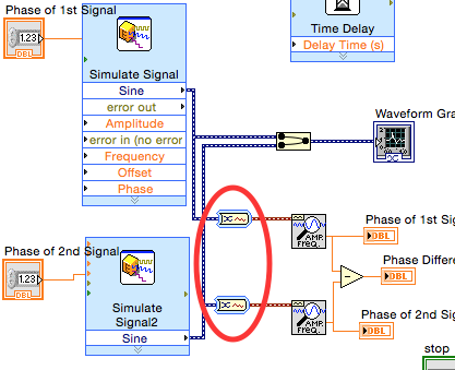
I need help in this program I am writing. I'm trying to calculate the difference in phase between two different simulated sinusoids. I searched online and found out that I could do that using retrieves your unique information and subtracting one phase to the next. However, I struggle to connect the wires, and I'm not sure why he does not connect properly. Forgive me if this is a fundamental problem, as I'm new to LabView. Thank you. The program is attached.
aclx
aclx,
It would be probably better if you posted your question for the LabVIEW Board rather than the Board of Signal conditioning. This Board gets about 1% only as much traffic as the LV Board and your question has nothing to do with conditioning of signals.
You have two questions.
1. the Type of dynamic data (evil) generated by the screw Express mask all the information about what's on the wire. It seems that the default conversion performed by the entry to retrieve only your Information.vi was in a table of waveforms. This gives a picture of phases out. You can tell what kind of data is on a wire or why a thread is interrupted by pointing the cursor to tool of wiring on the wire with the open contextual help window.
2. the relationship of phase between two signals of different frequencies is not defined. What moment in time should be used as the reference? How acquired or simulated signals relate to that time on the iterations of the loop?
The first issue can be fixed by explicitly converting DDT to a waveform as shown below.
For the second question, you need to define what you mean by the phase shift of two different frequency signals.
Lynn


Maybe you are looking for
-
How can I restore my tabs closed
Please forgive me if I do not exactly everything well it is my first time so if you need information out just answer and wrong type an answer for my problem as the title says I can not my tabs, once that I close them recently closed tabs, history opt
-
Satellite L305-S5955 - gel of the boot process
Toshiba Satellite L305-S5955Once it froze early in the boot process - until windows starts, indicating (to me) it must be material. John
-
Audio device of the Satellite A100-906 has stopped working
Hi all..the sound on my Satellite A100-906 simply ceased to function in Windows XP.I don't have something like installing a program, etc.I checked that the drivers are installed correctly but after that I just got it so I installed a new copy of Wind
-
Hello. First post here. I had problems with my sensor of ambient light in the night - in total darkness, the screen refuses to adapt to its brightness. The Adaptive brightness setting only works when there is a light source or if I reboot my phone. W
-
Chromebook 14-q010dx HP: HP Chromebook 14 does not illuminate
My HP Chromebook 14-q010dx (Chrome OS) is no longer powers on reliable after being arrested. Fresh thin battery, but Chromebook that occasionally feed after that be closed. I see the same behavior on a fully charged battery or connected via adapter/c