SMU-4330 remote sense
I'm trying to get the feeling of distance on the SMU-4330 to work. I have a sensor based bridge connected as shown in the manual. I can't find a property node for the remote sense. The remote sense works automatically when hooked or should it be set up?
I thought about it.
The 4330 do not correct the voltage at the bridge. They only correct the output of the sensor by the voltage sense lines back.
Tags: NI Hardware
Similar Questions
-
Hai iam Amaladas from Chennai (India) iam Remote Sensing and GIS researcher here most people using the Google Earth application and five members using Iphone, we need an app (India) of Google Earth?
https://www.Google.com/search?q=Google+Earth+app+India&ie=UTF-8&OE=UTF-8
-
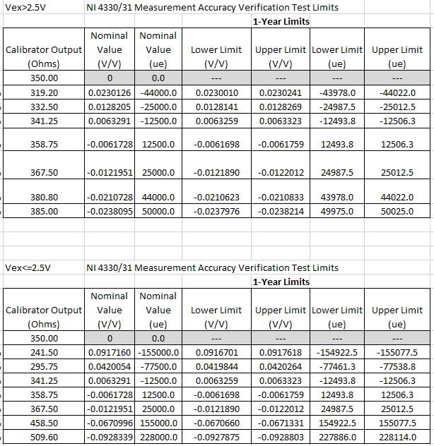
I tried to calibrate the SMU-4330 and getting coherent errors when you try to Gain accuracy test of the calibration Procedure 4330/4331 Express SC OR
For the three brand new 4330 cards, I get an error in table 5 of the manual for the outputs of calibrator: 295,8, 341,3, and 358,8, as well as an error in table 4 for the outputs of calibrator: 341,3 and 358,8.
I am fairly confident that I am following the procedures correctly. I was using the 5220 recommended A Fluke calibrator and the cards past all the other verification tests except the Test of accuracy of Gain.
Anyone have any ideas? Arrays of textbooks has been updated?
Thanks in advance
G'ory88,.
Please use the forums OR! In fact, we found some errors in these tables. We are working to correct the document, but here's a rough revised table for you:
I'm sorry for any inconvenience this has caused. Let me know if you're still having problems even with the table above.
Katie
-
wiring of remote sensing and shielding to the Earth, 9237 requirements
Hi, I have a set of scales (full-bridge) connected to a 9237 (in a 9172 chassis), and I have two questions regarding the wiring:
(1) requires remote sensing that you have two additional sons detach from the cell, to the place where the wires attach to the wheatstone bridge?
(2) where I should connect the shield of the load cell 50/60 Hz noise? to the Ex-terminal (as well as the Ex-fil)?
Thank you
Claire.
Hi Claire,
(1) Yes. Drivers of remote sense must be connected to the points where the voltage wires connect to the bridge circuit.
(2) Yes. The shielding must be connected to the reference of the unit, who is the EX - for the 9237.
See NI 9237 Instructions and specifications manual and this DevZone for more information.
-
BlackBerryContact returned from remote sensing
Hello
I hope someone can help me; is there a way to determine from the BlackBerryContact returned from remote research that the BlackBerryContact came from a distance search rather than a local search? A field in the contact?
Thank you
David
No, there is no field that indicates if the contact came from a remote research or is stored locally on the BlackBerry smartphone.
-
Hello
I want to put a public var to true when you press ctrl shift and set to false, then when they are not pressed. This is to link with some features of datagrid that respond differntly when Ctrl or shift are down.
onKeyBoardDown() is sussessfully followed when the keys are down, but onKeyboardUp is not when they are released. Why is this? Thank you!
stage.addEventListener (KeyboardEvent.KEY_UP, onKeyBoardUp);
stage.addEventListener (KeyboardEvent.KEY_DOWN, onKeyBoardDown);
private void onKeyBoardDown(event:KeyboardEvent):void
{
If (event.ctrlKey) //if control button is pressed
{
trace ("CTRL on ');
}
Else if (event.shiftKey)
{
trace ("SHIFT on ');
}
on the other
{
trace ('NONE!');
}
}
private void onKeyBoardUp(event:KeyboardEvent):void
{
If (event.ctrlKey) //if control button is released
{
trace ('CTRL off');
}
Else if (event.shiftKey)
{
trace ("off SHIFT");
}
}
To answer why your original code does not work, you use KeyboardEvent to indicate the current state of the 2 keys in a way ' if/else '.
For example, when you release the CTRL key, event.ctrlKey will always be false (because it is more of course). Same thing with the release of TRAVEL if you release that will always make it false.
Use the keycode as moccamaximum mentioned, but you have to detect combinations do not limit it to the "if/else".
for example:
var ctrlIsDown:Boolean = false;
var shiftIsDown:Boolean = false;
function onKeyBoardDown(e:KeyboardEvent):void
{
If (e.keyCode is 17)
{
trace ("CTRL on ');
the value of state var for CTRL
ctrlIsDown = true;
}
do not use on the other, separate logic
If (e.keyCode is 16)
{
trace ("SHIFT on ');
set var to SHIFT State
shiftIsDown = true;
}
}
function onKeyBoardUp(e:KeyboardEvent):void
{
If (e.keyCode is 17)
{
trace ('CTRL off');
the value of state var for CTRL
ctrlIsDown = false;
}
do not use on the other, separate logic
If (e.keyCode is 16)
{
trace ("off SHIFT");
set var to SHIFT State
shiftIsDown = false;
}
make a function to check the key States
If necessary here and making adjustments
based on shift or control separately
}
keyCode has limits, beware. Alternative keyboards are known to change the values for keycode of unexpected results. Modify if needed. Consider charCode and keyCode has other limits:
-
4 settings of thread for B2902 SMU
Hi all
IM using an EMS to discharge a battery (s), I need to set the EMS B2902A mode 4 son, if I understand correctly that we feel remote setting in one measure of VI, but I cant find it, anyone can help?
Steven
mgbglasgow wrote:
Hi all
IM using an EMS to discharge a battery (s), I need to set the EMS B2902A mode 4 son, if I understand correctly that we feel remote setting in one measure of VI, but I cant find it, anyone can help?
Steven
If it is not there in the pilot of the plane, I don't know, then you could certainly write a VI to activate Remote Sensing. The command should be in the manual.
-
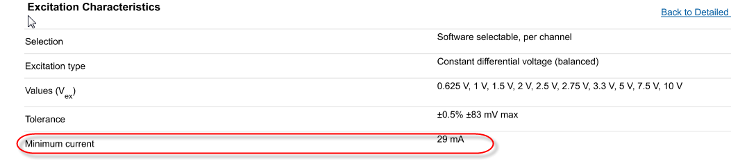
Confusion about the Source of excitement in the bridge SMU-4331 input module
Hello
I had some confusion through the input of the bridge SMU-4331 sheet module.
In the features section of excitement, its current Minimum as 29mA says. What it means. It can only current greater than 29mA delivery!
I think this should me Maximum current specification.
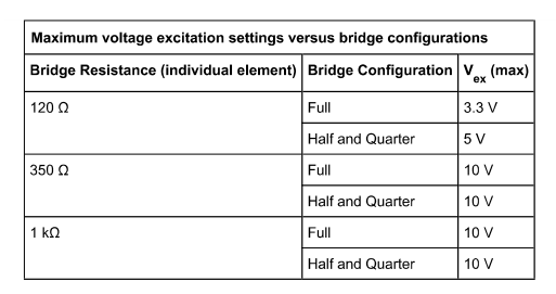
If you look at the table below
350 ohm resistance, the current should be 10V/350 ohm = 28.5mA
but for 1 K ohm, current will me 10V/1Kohm = 10mA, which isn't normal, if you specify current minimum as 29mA.
any thoughts?
Kind regards
Mirash
Hello Mirash,
I'm glad I could help!
As for your other question, the SMU-4330/4331 are inherently peripheral ratiometric. This means that they are designed to detect the level of excitement and range of the ADC to the appropriate scale. In this way, we can compensate for permanent changes in the voltage. One of our engineers wrote a big article really nice area on the subject I would recommend that you take a look at: Sensors of Measuring Bridge-Based with the ratiometric approach
See you soon,.
-
PXI chassis with remote hot-plug
Hello
I use the SMU-PCIe8371 with SMU-8370 remote control instruments in the SMU-1075 chassis in Vista. In order to see my instruments in MAX the chassis must be turned on when I reboot Windows. If I disable the chassis while Windows is running, I have to restart to be able to reuse the instruments.
Is it possible to make MAX see the chassis if it was not executed when Windows started or has been disabled while Windows is running?
Thank you!
Hello
You can disable and enable the bridge PCI to PCI in the Device Manager, but this is not recommended or supported. I also suggest that you turn off the chassis while Windows is running, which is essentially the same as the withdrawal of a card PCI of your computer while the PC is on. This can lead to problems with your system, such as the database of MAX, which isn't very fun to solve. The recommended method to start your system is always chassis first, followed by the PC, and to stop, is PC first, followed by the chassis.
-
I am aware that some MIDI messages (like aftertouch and maintain) can be filtered, but is it possible to block or filter the MIDI cc numbers (orders) all or part in MainStage 3? I am interested because I started doing concerts outside the city in which I present with my computer mac laptop and keyboards are rented. Unfortunately, many times theses keyboards are MIDI messages that screw my MainStage performance and there is not enough time to understand before showing. If I could program MainStage to ignore everything except what I really need (volume, expression, etc.) it would make life easier. Has anyone encountered this problem? I with my own personal keyboards as well, but I found them accordingly, that's why MainStage works very well when I play locally with my own material. Any help or ideas would be appreciated. Thank you
I don't think that Mainstage can filter other streams of midi data that you already mentioned in the tabs in midi in patch mode.
I often use Yamaha keyboards as controllers of the Motif series, for example, and they spit active remote sensing and midi sync. Although he's not trashing the way responds Mainstage, I have to manually disable sync midi on the controller itself and I can filter midi well active detection.
I think it would be cool to have Mainstage, be able to do this
-
Error-201427 on PXI-5122 since NI MAX system
I need to check that the PXI-5122 is supported by NO-Scope 4.0.0 under WINdows 7 64-bit. If so, I guess I can get a damaged card. The system was running under the old computer / code / drivers last month.
Scenario is this: I'm upgrading of already running code to a new computer and 32-bit 64-bit CVI CVI. After plowing, of code tweaks, PXI, 5122 digitizer shows through a new error in the code. I go back NI Max and I get this related error when I try to post.
"The driver could not communicate with PXISlot2, generates the following message:
Error-201427 to the autotest
Possible reasons:
The specified device is not supported in the API OR-DAQmx.
Specified device PXISlot2.
Seeing this, I have tried NOR updated, and nothing has been marked. I shut down the system and reseat the card. Then I checked the version of NOR-Scope (was 3.9.4) OR MAX I downloaded manually OR-Scope 4.0.0. Same mistake.
The 5122 is in slot 2 and NI MAX identifies the card as "2: NOR-PXI-5122"PXISlot2"
More information on the current system
Dell Precision T3600
Win7 64 bit Enterprise SP1
Spincore NMR TIming Pulsebalster PCI card
PCIe copper x 4 remote link to the chassis OR 1062 q
In the NI 1062 q
Slot 1: NI SMU-8370 remote control
Slot 2: OR PXI-5122
SLOT3: NOR SMU-5442
Slot 4: reports of empty in fact NEITHER SMU-8262 linked to a NI PCIe-8263 (shows in Windows, normal visibility NI Max is unknown)
Slot 5: OR PXI-6733
Slot 6: OR PXI-6733
Slot 7: vacuum
Slot8: OR PXI-5421
Measurement and Automation Explorer System Information (current after upgrade NI-Scope) is attached
Before I track down a loan 5122, I wanted to see if there are known incompatibilities that come to mind.
Thanks in advance.
There is a material-200313 error on the map (and the first replacement) as revealed by an earlier version of NIMAX (another computer and PXI chassis). The information contained in the attached document can help improve diagnosis in the future (rather than the more highest credits of the error).
With a third scanner system is running.
-
Place HP 34401 in Local with GPIB-USB-HS Mode
Hello
I'm using LabVIEW 2010 SP1 to control the 34401 HP with the NI GPIB-USB-HS device. I use I/O built-in 34401 instrument drivers.
If I plugged in everything, the 34401 will be immediately placed in "Remote" mode when I run my software. However, I would like to be able to use LabVIEW to force the 34401 to 'Local' mode Unfortunately I could not find a way to do this. I tried Close.vi, but has no effect.
Here are my planned operation if it makes things clearer:
- Launch the software
- Initialize the 34401
- Place the 34401 in the 4W resistance measurement mode
- Pass the 34401 in "local" mode so that the end user can adjust a knob until the desired resistance is obtained while seeing the value of the resistance to change on the 34401
- Re-initialize the 34401 when I need to switch to another measure
If not, is there a way to get the 34401 to permanently display how it is taken in remote mode?
Best regards
Ian Williams
Linear Applications Engineer
Product precision linear, and remote sensingThe feature I mentioned does exactly the same thing except that you have to do this awkward analysis of the address. It's a VISA function you have just used the search button to find (and have lit context-sensitive help) to obtain explanations of what he does.
-
amplification of the strain by using the cDAQ
Hello
I am a newbie in the use of DAQ hardware and hope someone can help out me.
I recently bought a cDAQ with the NI 9237 to measure the strains. The strains that I try to measure are very small 1 series micro. A bit of research showed me that I need to amplify the signal to measure these small strains (correct me if I'm wrong). But I'm not able to find amplifiers for the cDAQ.So, the questions I have are-
1. is it possible to measure these small strains (1 strain micro) using the cDAQ? If so, do I need an amplifier?
2. If I need an amplifier, are there more specific for the cDAQ with the 9237? If this is not the case, how and where can I get one?
Thank you
SID
SID,
These results were very shocking for me also, so I looked into it further. It seems that the 9237 can do better. Assuming you're within 5 degrees of the calibration temperature (25 ° C), 9237. 05% of span of error and. 05% offset error. With the range of configuration and 25mV/V full-bridge, you can calculate the absolute accuracy of the 9237 with the following formula. (Sound of full-bridge = 0.9 microV/V)
absolute accuracy = (gain error * reading) + (error offset * range) + (noise)
Do the math, we get
25mV/V + / 25.9 microV/V
In a full-bridge configuration: V/Vex =-(Gauge Factor) * strain
With a typical GF of ~ 2.0, we can say that the accuracy of the strain will be
12.5 mm/m + / microm 12.95/m
It's a little more in the range that you hoped for. Sorry for the confusion.
If this does not work for you, we sell solutions PXI who will be able to measure more precisely. Similar math help and type of configuration of full-bridge with SMU 4330 plug, we get:
12.5 mm/m + / 3.48 microm/m
In my view, that it is card data acquisition based on a bridge more precise and accurate that we sell. It requires a controller/chasis PXI.
Please let me know if you have any other questions!
Sincerely,
-
need to know if the NI 9237 - no compenstation such temperature on bridges and shunt calibration
need to know if the NI 9237 - no compenstation such temperature on bridges, also, I need to know if she calibration shunt.
Hey invzbl_rkl,
The NI 9237 - can do both remote sensing and Shunt calibration. You can see the details on how to connect the bridge in the USB-9237 user guide and more details about compensation in the article attached Developer Zone on measurement of strain.
Specifications and NI USB-9237 User Guide
http://digital.NI.com/manuals.nsf/WebSearch/B218E7E6DDB1D4518625738600784930Strain with gauges
http://zone.NI.com/DevZone/CDA/tut/p/ID/3642 -
Hello
I currently have the following equipment:
cDAQ-9178
OR-9401
OR-9219
I use the module OR 9401 to drive the output PWM signals is calculated by a PID controller in two controlled thermal systems. I use the NOR-9219 module to measure temperature, such as remote sensing by thermistors. These temperature values are used in my PID controller to calculate the error.
I am now interested in measuring a number of other temperatures on my device using thermocouples (these temperatures are necessary only - no controller action based on them). 9219 module is ideal for my PID controller, that I can use to detect the very precise Thermistors, but it has only 4 entries. I'm considering adding a NI 9213 Module to my setup to activate the additional analysis that I need... My question is this - this module will be compatible with my setup? for example can I simultaneously run two analog modules (9219 & 9213)? Is it reasonable to try to make the PID regulation and this extra temperature monitors simultaneously?
Thanks in advance for your comments!
See you soon!
Hello JB_1,
What is are describing is undoubtedly reasonable and feasible with the hardware you have. 9178 has several Motors synchronization to analog input, so you can configure separate tasks for two different modules if you want to acquire simultaneously and at different rates.
-Christina
Maybe you are looking for
-
How can I sort more by last used date?
Hello: How can I sort the apps on my phone by date of last used? I know, that there was a way in ITunes but this option isn't there anymore. It's by name, size, or type I believe. I have far too many apps because I let my grandchildren play games.
-
Cannot process the MTP. CC says Co tech is Firefox problem
IPS, a shipping company internet indicates that the credit card payment screen crashes because I'm on Firefox. They want to change me browsers. I've used Firefox on a previous transaction, but they say sometimes it works and sometimes it doesn't. The
-
HP laptop laptop 15-ac198TU: is my normal hard drive?
I just bought my laptop and heard this noise of crackling, as similar to the video of my hard drive. Is this normal? Or is my drive defective? https://www.YouTube.com/watch?v=hBcFLZ2S7Fk
-
original title: cannot open or copy some files within the home network I have a home network that are connected by a router. A (main) pc is connected via a cable to a router on Windows XP pro sp3.2 other laptops running Windows 7 connected via Wifi.
-
What do mean flicker alternating orange and blue lights on Dell Inspiron 1420 with vista?