The simulated signal RMS
Dear Susan!
I took a glance on your application.
It's really good, but the calculation of the effective measures should not be implemented in the Simulation of control loop, since the calculation will be dune for each point this may require Ness on the graphical indicator, when you run the code.
I made a few changes and used Uilities int Simulation palette palette function of collector . This function allows to collect data and do the treatment on it, the end of the simulation.
Please find attached code.
If you have any questions, feel free to ask.
BR,
Tags: NI Software
Similar Questions
-
How the input signal updated step in simulation?
Hello
I have my own model of transfer function. I did first with Matlab/Simulink simulation and succeeded. I use the Signal Generator in Simulink to get out my custom step signal. I modified my step so signal to:
t = 0 y = 0
t = 0.1 y = 0
t = 0.1 y = 50
t = 10, y = 50
t = 10 y = 65
t = 30 y = 65.It's the kind of staircase input signals. Now, how to build such this approach custom signals to be fed in my transfer function. I tried the function 'Not of Signal' of the 'Simulation', but I can only get the 50 and I don't know how to add more "staircase" in my input signals. Could someone help me?
-
Error to the element of the queue with simulated signal, but not with the DAQ hardware
Hello. I get an error code 1 when I run my VI in simulation mode, which is only 3 simulate subvis signal at different frequencies. The block diagram shows jpg file and the probe is after I stop the VI. Note that there is an invalid refnum. I don't know why that is. I am also including the watch of the probe after a few iterations, there is no error on the probe 64 until I stop the VI, and also noted that there have been no queue items. This of course means that I don't get to remove the data in loop 2. An interesting note is that the system works fine when I run the program in data acquisition mode, which is the other case behind the 'simulate signals. " In this case, the only thing is the DAQ assistant and dynamic data of the tunnel cable. Everyone can't see what I could do wrong? Thank you.
Thanks for looking at my post. I thought about it about five minutes ago. I didn't have a timeout on the handeler event, so it was not double check for new items in the queue. I don't know yet why the probe shows showes that items have not put in the queue because they certainly were. Maybe "queue items 0" means that there are no items saved in the queue. ?
Your concern is interesting and deserves a check... I just ran it without registration, and it seems that the release of the case (the default) record structure is just an empty DDT, a placeholder, I guess.
-
Align the two signals and measure the Phase Shift
Hello
I do an experiment in which I use the NI USB-6221 DAQ card. The jury is able to make 250 k samples/second. I want to measure two voltages in a circuit and find the phase shift between them at frequencies between 1 and 10000. First I ouputted a wave sinusoidal frequency variable through the Commission and applied to a test circuit. Then I used the Board to measure the two tensions consecutively (thus reducing the maximum sampling frequency at 125 k). I used the signals align VI and measured the two phases and then calculates the phase shift (VI attached in Phase 1). It worked well for the test circuit I built in which the phase shift went way logarithmique.20 degrees ~84.5 degrees and then stabilized. At frequencies above 5 000 Hz phase shift must have remained constant, but it varies more or less 1 degree. When the phase shift is 84.5 degrees, present a degree of variability is not particularly explicit. When I asked my program on the circuit that I really wanted to measure, the phase shift went from-. 5 degrees up to about 1.2 degrees. The change in the values of phase shift at high frequencies (> 3000) was environ.2 degrees. Given the small phase shift, this variation is unacceptable. Now I tried to use a sequence to each blood individually (increase the maximum sampling frequency to 250 k) and then align the two signals and measure the phase of each shift. When I use align it and re - sample Express VI to realign the two signals, I get the message "error 20333 analysis: cannot align two waveforms with dt even if their samples are not clocked in phase." Is it possible to align two signals I describe here? I enclose the new VI as Phase 2
Matthew,
I think I have an idea for at least part of the problem.
I took your program data and deleted stuff DAQ. I have converted the Signal on the chart control and looked then what was going on with the signal analysis.
The output of the Waveforms.vi line has two waveforms, like the entry. However, arrays of Y in the two waveforms are empty! It does not generate an error. After some head scratching, reading the help files and try things out, that's what I think is happening: the time t0 two input signals are 1,031 seconds apart. Since the wavefoms contains 1,000 seconds of data, there is no overlap and may not align them.
I changed the t0 on two waveforms are the same, and it lines up. The number of items in the tables is reduced by one. Then I increased the t0 of 0.1 seconds on the first element. The output had both greater than the entry by dt t0 t0 and the size of the arrays was 224998. Reversing the t0 two elements shifts the phase in the opposite direction.
What that tells me, is that you can not reliably align two waveforms which do not overlap.
I suggest that you go to 2-channel data acquisition and that it accept the reduced sample rate. You won't get the resolution you want, but you should be able to tell if something important happens.
You may be able to improve the equivalent resolution by taking multiple steps with a slight phase shift. This is similar to the way that old oscilloscopes of sampling (analog) worked. Take a series of measures with the signal you are currently using. The make enough average to minimize changes due to noise. Then pass the phase of the signal of excitement to an amount that is smaller than the resolution of phase of sampling rate and repeat the measurements. Recall that I calculated that for a 5 kHz signal sampled at 125kHz, you get a sample every 14.4 degrees. If shift you the phase of 1 degree (to the point/mathematical simulation), you get a different set of samples for excitement. They are always separated by 14.4 degrees. Take another series of measures. Transfer phase another degree and repeat. As long as your sampling clocks are stable enough so that frequency does not drift significantly (and it shouldn't with your equipment), you should be able to get near resolution of what you need. The trade-off is that you need to perform more measurements and may need to keep track of the phase shifts between the various measures.
Lynn
-
FPGA: the internal signals in ModelSim display
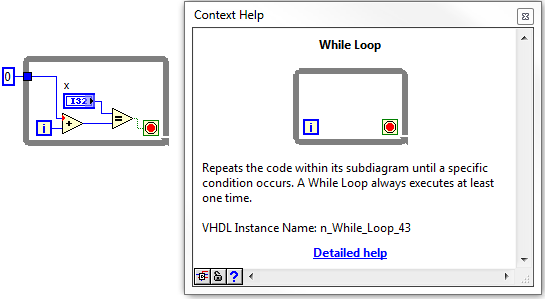
I have a piece of code written LabVIEW FPGA in that I am trying to simulate in ModelSim. I followed the instructions in this link, but the example is a simple incrementer with no internal signal (only the input and output).
I created a test bench and started the simulation, but the macro provided .do only adds the entries and exits to the wave window. ModelSIM lists pages and pages of processes and signals that can be added to the waveform window; all have names completely opaque. I found something called 'TheWindow', and then a subdirectory called "Thatcher" and added all these signals to the waveform window. The names are things like ResHolder00000000000001 and provide no information on where they came from.
I tried to assign labels to the sons of my LabVIEW diagram, but that did not help at all in creating useful names. I need to check the progress of States in my VI but can't find anything that seems like the appropriate signal. A lot of available under 'Thatcher' waveforms are waveforms static, uninitialized, or both. How can I assign names to internal signals so that the waveforms are actually intelligible?
On a side note, it is also a problem in the synthesizer. I'm used to using the synthesizer output to 'pre-debug"my code, but LabVIEW seems to ignore the process of inference any macro. I tried to put a SCTL with an incrementer and LabVIEW does not infer a counter. I have never seen one of my machines of State recognized in the synthesizer, even if the code works correctly.
Using ModelSim PE 10.3, I understand is not "officially supported", but the fact that the synthesizer and the Simulator have the same denomination made problem wants me eliminate this as a problem. I do not use one of the PE extensions on the version SE.
Hi Nick,
If it is not the most readable, its not too hard to find signals that you are looking for. Your biggest help will be context-sensitive help in LabVIEW. If you hover over the structures, nodes, or son, in your LabVIEW FPGA design, at the bottom of the help context window, you'll see what we call the 'name of the VHDL Instance".
Once you navigate through the hierarchy down through the window, in the VI, you should start to see some of your top-level objects, such as while loops etc. From there, you can navigate down in whatever the level and find the wire you are looking for.
I did not have the ModelSIM on my machine, but it works for the ISIM. I wish they had a search function, so you can just type in the signal you are looking for.
-
Simulate the loop Signal splitters
I am using a loop for the phase shift signal simulated on a 360 deg. My loop will change, amplitude, frequency, offset, but it will not change the phase, is - anyone know how I can do this? I have attached a code that indicates the fundamental problem.
Great! I should really like to try the reset signal entry. Thank you!
-
Why my MB Air decreases the wifi signal
My 2012 13 "core i5 MacBook Air running different operating systems will remove the wifi signal and it is getting worse. someone at - it a reason why?
How your MacBook Air running different OS version? However, the Wi - Fi signal fell to each version?
This always was a problem or just started to happen? Up to now, what did you do to try to solve?
-
After updating my iPhone 6 (9.3.4) the WiFi signal becomes very low! I did everything, but the problem does not stop! I don't a not update my other devices & their very good WiFi signals. Please help me solve this terrible problem...
Here's a tip for the user on the problems of Wi - Fi. Suggest from the top and bottom. Maybe one of them will help you.
(1) restart you device.
(2) resetting the network settings: settings > general > reset > reset network settings. Join the network again.
(3) reboot router/Modem: unplug power for 2 minutes and reconnect. Update the Firmware on the router (support Web site of the manufacturer for a new FW check). Also try different bands (2.4 GHz and 5 GHz) and different bandwidths (recommended for 2.4 to 20 MHz bandwidth). Channels 1, 6 or 11 are recommended for 2.4 band.
(4) change of Google DNS: settings > Wi - Fi > click the network, delete all the numbers under DNS and enter 8.8.8.8 or otherwise 8.8.4.4
(5) disable the prioritization of device on the router if this feature is available. Also turn off all apps to VPN and retest the Wi - Fi.
(6) determine if other wireless network devices work well (other iOS devices, Mac, PC).
(7) try the device on another network, i.e., neighbors, the public coffee house, etc.
(8) backup and restore the device using iTunes. Try to restore as New first and test it. If ok try to restore the backup (the backup may be corrupted).
https://support.Apple.com/en-us/HT201252
(9) go to the Apple store for the evaluation of the material. The Wi - Fi chip or the antenna could be faulty.
-
App-Manager does not connect to the Simulator OS Firefox on Windows 7
OS: Windows 7
Firefox: 28
6.0pre8.20140112 Simulator 1.2 Firefox OS
When I run the simulator it opens fine and I see a Firefox OS Desktop
But the App Manager does not connect. The console at the bottom right says:.. localhost:56455 options (the port varies)
.. connection timeout. Possible causes: has not clicked 'accept' (guest).
.. .disconnecting
.. .disconnected
I have disabled my firewall, restarted firefox and even system - did not help
There is a similar bug - but I don't know if we are talking about the same thing:
https://support.Mozilla.org/en-us/questions/988385Thank you
Well - I already knew these links and I can't find anything useful
Anyway, I tried the Simulator instead of 1.2 1.3 (unstable)
This one works very well -
Satellite C850D-11 q keep loses the WIFI signal
Toshiba Satellite C850D-11 q BT Hub 4 Realtek drivers
I lose the wifi signal at least twice a day. Same message to loose / broken cable and reset the wireless card. Realtek has informed me that I have the latest drivers. The present is Realtek RTL 8188CE Wireless Lan 802.11n PCI-E NIC hub is new. With the help of BT, I now use the 5 GHz as the hub is on a shelf just below the laptop.
I don't know what to do else and thought someone here can get an idea of what to do next apart from the change of servers!
Thank you
LEA
I wait too long? Has decided to search for updated drivers. Goes up to 8.1 not 10.
Then decided to download the manual. Informed, there was one, but there is no way to access it. Message received this laptop modified 10/15/15. Well thank you very much for this. Message also States that "with this tool, you will get urgent information about updates for your computer. I clicked... Web page could not be found.
Large. Because buying a new laptop, but it will not Toshiba, that's for sure.LEA
-
Default device in the Simulator
Hi guys
Is it possible to set the default device Simulator? I always want to turn into one of those more peripheral NOT. All except 6 + and 6 s +.
It is annoying when it does not fit in my MBP 15 ".Thank you
You can try to reset the Simulator, but I think it's just the default value for the last type of device used.
-
The Bluetooth signal my audio is intermittent. How can I fix?
The Bluetooth signal my audio devices is intermitten, how do I fix?
It may be the audio device... However, try to reset the memory NVRAM and SMC.
Barry
-
Find and replace the name of the various signals of different value
Dear members
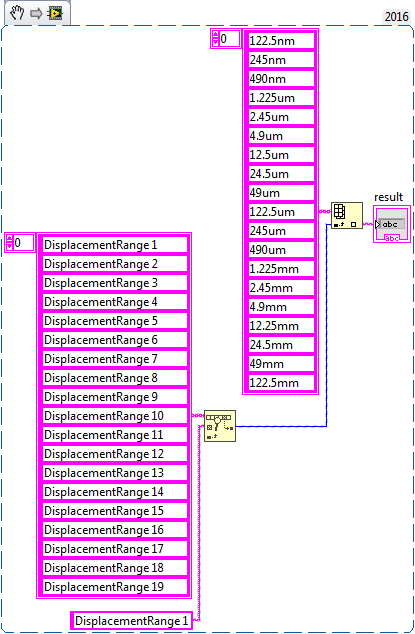
I run a program where I get the output signal ' displacmentrange 1 '...
"displacementrange 19" I need to replace this name with another name
for example
When come signals
displacementrange 1, it should show 122.5nm
displacementrange 1, he must show 245 NM
displacementrange 1, he must show 490 nm
concerning
Benoit zafar
Hello deutchland.
I hope that I have understood correctly, you can use find in table and then use the array index
-
Hello.
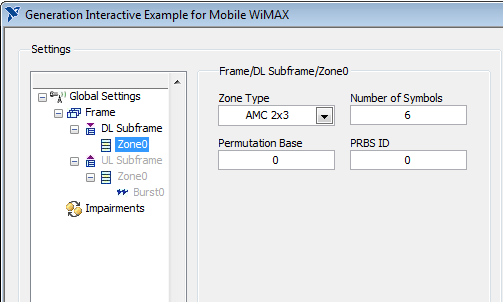
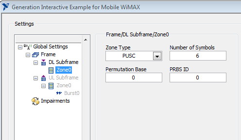
I use a VST OR to generate the WiMAX signal. I installed NO measure costume for Mobile/Fixed WiMAX 1.0 on the calculation. But I can't find any option on the front panel of the combination of the generation to enable AMC or PUSC for generated signal. This feature exist at all?
Thank you.
Hello sam2013ni,
That's all I see for AMC and PUSC. Look in "box Type".
Best regards
-
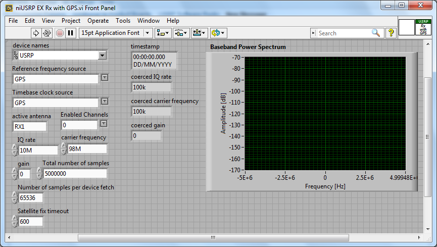
Acquisition with USRP 2953R of the GPS signal
Hi all
How can I configure a 2953R USRP receive GPS signals? I have an antenna VERT900 connected to the GPS ANT of the USRP port, but in the example VI 'niUSRP EX Rx with GPS', I can't reference this port in the field 'Active antenna'. I put only things like TX/RX or RX1 etc. Should what values I put in other areas as well? I know that the L1 band is 1575,42 MHz.
Hello
The example you posted shows you how to acquire an RF signal on the ports of the USRP with internal clock RF and sources of reference defined in the GPS.
To make it work properly, you must have a GPS antenna connected to the Terminal on the GPS device and installed in a place that receives a good level of GPS signal.
The other control of antenna on the schema defines the port on which to receive the RF signal.
If you want to capture and analyze the signal GPS (RF) itself, you can tune into the front-end RF (carrier frequency) at the right frequency of GPS band and connect your GPS antenna to the RF port.
You can use the simple niUSRP EX Rx continuous Async.vi in this case (but may not work due to the very low consumption of GPS RF signal)
Maybe you are looking for
-
How to take a screenshot with 10 IOS?
How to take a screenshot with 10 IOS?
-
16 GB memory in a 15 "laptop Macbookpro 2010
OS X Yosemite Version: 10.10.4 (14E46) MacBook Pro (15-inch, mid 2010) Processor: 2.4 GHz Intel Core i5 Memory: 4 GB 1067 MHz DDR3 Graphics card: NVIDIA GeForce GT 330 M 256 MB I work as a designer and need to maximize the amount of memory as much as
-
I'll try to find the 'Clipboard' on my computer
I can't find my Clipboard on my computer and I tried to do a screenshot captures some of my homework, and he says it will be on my 'Clipboard', but I can't find my Clipboard.
-
When I insert a dvd, the dvd is not recognized and I wonder ' to install a dvd or disk etc.
-
test_fwktutorial.jsp does not start... Waiting for [IP address]
JDeveloper installed and configured for the 21662342 Patch. For EBS R12.2.5Try to run test_fwktutorial.jsp. IE will start, but he's white with spinning cursor. No other answer... until that don't get server error internal 500 after 10 minutes.Here