Toolkit NOR EIP and SMC EX600
Hi all
I am very new to connect via Ethernet/IP and I got the mission to integrate a SMC EX600 Ethernet/IP fieldbus module into a labview system. Currently, the EX600 is attached to 10 solenoid SMC and SMC 8 SOP 2 digital input modules.
I did some research on here, and it seems that I got myself a bit confused on the ability of a Communication and the Communication Scanner adapter. What I read, the EIP Toolbox is an adapter, so it cannot start I/O communications between other adapters. It turns out the SMC EX600 is also one adapter per pg 29 of the data sheet (http://www.smcworld.com/upfiles/manual/e/EXxx-OMN0032.pdf), bad luck. So I have reason to assume that implicit messaging is out of the question?
This might be fine with me, as I don't need a constant flow of e/s and I would rather contact the EX600 on a point-to-point basis. In reading some posts, I found that explicit messaging is supported (http://forums.ni.com/t5/Industrial-Communications/SMC-Valve-Ethernet-IP-Communication/td-p/2979621). This means that I can always get the status of a digital input port or set the position of a solenoid, correct?
Define States of solenoid valve using messaging explicit or by reading the data sheet, I'm at an impasse on how I actually read entered digital. Could someone clear this up for me? Thank you.
Quick update,
After a careful reading, I was able to communicate with the MSC EX600. Using the example of Assembly (Explicit) .vi access Instance data I could read the State of the digital input modules, as well as to define the State of the digital output module and operate solenoids on valve battery module.
On page 60 of the manual (http://www.smcpneumatics.ie/media/EX600-SEN1_2-Ethernet.pdf), it describes which instance of the assembly to use when specifying inputs or outputs. Using these values, I get a decimal number response corresponding to the State of each module. Convert this number in binary retrieves the value of bit for each individual digital line. Digital outputs are processed similarly except that you write the digital number.
Valves after your output in table modules and are managed by groups of 4, because there might be 2 solenoids by valve on some configurations. 0 disables the block of 4 and 255 turns on the block of 4. The correct binary value convert decimal to obtain the desired combination.
I hope this post can help someone who has the same problem on the road.
PS: Don't forget to put your EX600 have a static IP address before you do all this. The utility BootP rockwell has not worked for me, but this one did http://www.anybus.com/support/support.asp?PID=509&ProductType=Support%20Tools
Tags: NI Products
Similar Questions
-
NOR-9472 and SMC solenoid valve
Hello
I'm writing the code for the valve of the SCM activity. I need to control the amount of time that the tap is open. The tap is connected to the / 0 on the NOR-9472
Don't know how to start the problem.
Second, I want to save data to an accelerometer in the VI even.
Yet once again, don't know where to start. If someone could please tell me some examples, it would be fantastic.
Here I have two screws, one to control the faucet, the other to the data recored, separate and have them both in an another vi?
See you soon
K
I wrote code examples that if everything will work well for you, or at least give you an idea of what I was talking about. There are three cases
-Wait, the VI is waiting for to press you the fire button
-Acquire, the VI changes the value of the solenoid valve and starts the acquisition of the accelerometer for a period of time
-Analyze, the VI performs an analysis of the data and then returns to the waiting state.
-
EFI and SMC firmware MBP 8.1 do not match list Apple
Hi all
I have a MacBook Pro 13 ", beginning 2011, 8.1.
I changed the hard drive with a Samsung SSD 850 EVO and installed the OSX El Capitan 10.11.4 Version (15E65) with a clean install (format, then install).
After that, I noticed that my fans are working more than usual. So I checked the SMC and EFI.
When I check the presentation of the material, here's what I find:
Model identifier: MacBookPro8, 1
Boot ROM version: MBP81.0047.B2C
Version of the SCM (System): 1.68f99
But it seems my SMC and EFI firmware do not match Apple list/recommendation:
MacBook Pro (13 inch, early 2011) MacBookPro8, 1 MBP81.0047.B2A (2015-001) 1.69f4 (SMC 1.7)
I found this information here:
On the updates of the EFI and SMC firmware for Mac computers with processor Intel - Apple Support
I am trying to update, but I received the following message: "this software is not supported on your system."
Someone at - it already had the same issue on the fans or mismatch SMC/EFI?
Kind regards
Carpet
Hi the-Mat:
I have the same exact computer and the exact same hard drive. Here are a few impressions of screen.

My information is the same as yours.


The version that you and I have is a more recent version. We have MBP81.0047.B2C instead of B2A.
< Alter > for your fans, try the following:
Try the PRAM reset: reset the PRAM
And try the SMC reset: Reset the SMC
How to reset your Mac SMC & PRAM - and why: reset the SMC & LANDAU
Kim
-
Toolkit ECU Measurement and Calibration does not run when I build an executable.
I did a LabVIEW application that communicates with a target using CCP (with ECU Measurement and Calibration Toolkit).
The source code of LabVIEW works OK, but when I create a .exe file, it does not work.
I tried to copy the Toolkit ECU Measurement and Calibration dll:s in the same folder as the .exe file, but I still get error messages.
What should I do to get the run .exe file?
Do you have you created an "Installer" and installed on the laptop?
If yes have you selected this Toolkit (ECU Measurement and Calibration Toolkit) to add to the installer when creating the same thing?
Just try this approach once...
-
Keithley 2000 not identified NOR Measurement and Automation Explorer using GPIB
Hello
I recently used NI TestStand and NI MAX with IVI drivers to get my working(using USB) peripheral. He has worked successfully for TG5011 and TDS1002B Oscilloscope function generator.
Following the same procedure: I started with 2000 model DMM of Keithley with GPIB.
I am facing difficulties in finding my camera on OR-MAX devices and interfaces. I use a GPIB KUSB - 488B USB adapter to connect.
I can interact with the device of VISA Interactive Control and KUSB diagnosis tool and you can see the device in the device Windows and KI-Configuration Utility Manager. Surprisingly, I don't see GPIB Board in the NOT-MAX.
Help, please.
System details: NI-VISA 5.2 installed on Windows 7, KUSB-488 driver installed in command compatibility mode OR. (only ieee_32m.dll is present), installed UN NOR-488.
Thank you
Martin
To help all those who have read this thread:
I had the Keithley 2000 NOR-MAX and NOR-Test Stand using IVI Driver (for Keithley 2000 of NOR) using the KUSB - 488 B (GPIB to USB adapt from Keithley).
Layer of keithley installed IO Keithley and I can see the unit property. I then followed the procedure for IVI MAX and TestStand pilot program and IT WORKED!
Please find attached the screenshots for Visual clarity.
Thank you and best regards,
-
A NOR-RFSG and NOR-DAA on Labview test error
Hey guys,.
I'm trying to run a VI, but by testing vi which compose it, I got an error on close vi NOR-DAMA and the narrow vi NOR RFSG (as shown on the picture). Do you have a solution for me please please?
Thank you
Thanks guys,.
I use 2 MIMO blocks, 1 vote against and 4 NOR 5663E (3 slaves and 1 master) and other with 4 NOR 5673E (3 slaves and Master 1 also). I found the solution, this morning, the problem was due to an obsolete vi, I just take a version of Labview 2012 some vi (such as initialization of niRFSA and a few others) and the problem was solved!
Thank you for helping

-
Modbus Toolkit NOR is not reliable?
I'm controlling a Watlow F4 in LabVIEW using the toolkit to add-on modbus. When I started to write this application, I used some modbus screws that I found in the devzone, but that he was not too keen on the use of unfamiliar code someone else. I thought that using of NOR would make things more robust. Instead, I am now meet delays and bad data reads.
I am running a diagnosis now, read a series of books about 40 and comparing the table resulting in a well-known data table. The toolkit OR failing to duplicate the right data within 5 tracks. I have received from the Commission on the screws have executed for, let me check... 96 iterations without error so far. What is the problem? Someone else has complaints about the modbus Toolbox?
Has anyone used tools Automated Solutions .NET (http://www.automatedsolutions.com/products/dotnet/ascomm/mb.master.serial.asp)? Or other 3 rd party tools?
Thank you
Ed K.
If you speak
http://zone.NI.com/DevZone/CDA/EPD/p/ID/4756
It is not officially supported, and there are a few bugs with it (just check the comments). The big one is that MB CRC - 16.v returns a u8 instead of u16. Fixing that is easy and will normally be your problem. You can try the other bug fixes if they seem as if they were relevant. The official way to use modbus is via the dsc module.
http://sine.NI.com/NIPs/CDs/view/p/lang/en/NID/1010
I use the first library, so I tried something else.
-
After internal reset PRAM and SMC microphone still does not work properly
I've recently updated to el capitan. For the first time that I had to use the microphone internal, so I went to the system preference, the maximum capacity, the value clapped my hands, but the microphone reacts just as shown on the scale bar. So I reset the SMC first then the LANDAU and now it reacts a little more because I clap my hands, I want to tell the scale bar that detects the incoming sound shows like 5 spots (and there are 15 points). I tried to register and the sound of the recording is very low. Is this normal? What I need to fix my mac (3.06 GHz Intel Core 2 Duo, 4 GB of DDR3 memory a 1067 MHz, GB 999,35-909, 89 GB free)? Thanks for any response.
Susan of morro bay , October 28, 2014 16:21
in reply to Sirae87 UsefulI cleaned the little tiny micro holes - and it worked:
I also had a problem with my internal microphone. In system preferences > Sound > entry, I had the internal mic selected, and the entry level bar would show some activity when I typed in the top of the computer, but not when I spoke. So first of all, I had to figure out WHERE the microphone was actually and I googled and found this on top of my iMac - a very small circle of TINY holes, right in the Middle at the top of the screen. Turns out I have had covered with a decorative Angel, using a sealant that is usually used to stick things to the surfaces. I removed the little angel and PuTTY... but did not always receive my voice recording in the bar of entry-level in sound preferences. I used canned air to blow at the level of the tiny holes, but that did not help. Finally I found a brooch (thinking it was actually too thick, drill holes of small microphone) but I WAS able to push the small holes - so I poked each other - and voila - my internal microphone now work! Yay!
-
Hello
The OR Web site mentioned the XNET interfaces are compatible CAN - FD. Could you tell me which are the XNET interfaces with FD CAN 11898 - standard 2:2015?
Kind regards
Hello SmileBoB,
Supported devices:
In general, the family of NOR-XNET CAN interfaces of is designed to be high performance modules that are easily adaptable to new standards and protocols. Since the physical layer CAN FD is very similar to that of high-throughput CAN, all interfaces CAN of NOR-XNET that support high-speed CAN communication also support FD CAN with bit rates up to 8 Mbit/s.
The list of NOR-XNET interfaces that support communication CAN FD is below:
PXI
- OR PXI-8513/2
- OR PXI-8513
- OR PXI-8512/2
- OR PXI-8512
PCI
- OR PCI-8513/2
- OR PCI-8513
- OR PCI-8512/2
- OR PCI-8512
CompactDAQ or CompactRIO
- NEITHER 9862
- OR high-speed/FD CAN cable transceiver for us with the NI CompactDAQ and NI 9860 compatible controllers
For X-NET 15.0 OR > http://digital.ni.com/public.nsf/allkb/588B7A1E9F2419B086257F1D00667F8D?OpenDocument
For NOR-XNET 15.5 and 16.0 > allows customers to choose between ISO CAN FD and non - ISO CAN FD in the software.
Understanding CAN with data Flexible rate (CAN FD) > http://www.ni.com/white-paper/52288/en/
I hope this helps!
Best regards
-
difference between NOR-USRP and UHD
Hello
The goal of my project is to develop both the driver code for a custom daughterboard and a control panel of vi Labview to change the properties of Remora.
I have developed the UHD Linux to include support for the follwing the format of the existing Ettus committees daughter card. This all works very well in conjunction with GNU radio/RCMP.
Now that I am developing a Labview application to control the Board of Directors, I had to walk away from Linux, because there is no support for the USRP in Lunix LabVIEW.
I'm just here doing with Windows and am about to install the kit of NOR-USRP for Labview support.
I'm worried that it's a dead end, however. What is the NOR-USRP? What is a wrapper that allows to serve as an interface with the API UHD Labview? Or is it another pilot for the UHD?
I was counting on the construction of the UHD in windows to include the patch I made for our daughter and then to develop a top-level control system in Labview. In my reading so far however, it seems that the NOR-USRP is not the UHD, a stand-alone pilot with his own material. If NEITHER-USRP and UHD are mutually exclusive, how do I build the USRP-OR source? (assuming that it is the code of industrial property)
More generally I could frame my question: how to develop support for the drivers for my daughter card that I can use it with Labview?
After all, I heard one of the main goals the USRP is sold, is to allow the development of Council of girl. It goes without saying that it should be possible to use development environment NOR?
Any advice on what I need to install/build to set up a:
LabVIEW-driver >-> USRP-> card girl custom
development environment would be greatly appreciated.

Alex
Alex-
Your request seems very interesting and innovative. The NOR-USRP driver is designed to work on a specific version of UHD and a specific image of FPGA. In order to provide a user experience that is refined it has been tested with the NI USRP-29erxx materials and was not supposed to be recompiled by the end user or used with custom Remora.
That said, you can call labraries and communicate with your own internal radio via a UDP socket GNU applications. Based on the little information I have on the application I would recommend remaining under Linux and the use of LabVIEW for Linux. You will have the ability to call libraries and use UDP as I've described. If you choose to switch to windows, you can add a few basic IP capaiblies for functions / toolboxes that run only in Windows operating system.
Erik
-
How to speed up loop DAQ triggered using NOR cDAQ-9174 with NOR-9215 and NOR-9402
Hello
I use LV2010 and NOR-DAQmx 9.2.2. I have a NOR cDAQ-9174 with a NEITHER-9215 4 channel 100 k simultaneous ADC and NOR-9402 4 channel DIO module trigger and reset.
We run WinXP sp3 on a Dell M4400 core 2 duo @2. 26 Ghz.
I used the code example NI DAQmx for acquisition of tension with trigger HW. My goal is to try all 4 channels on the 9215 simultaneously when a trigger is received on channel 0 of the 9402, after data is read, I use channel 1 on the 9402 to reset the trigger of the target material. I have a version of this work, however the maximum event rate is ~ 16/second. I have the Setup 9215 for finite samples / 10 samples per channel which is ~ 400uSec of conversion time and I realize he is above in the appeal of vi, but ~ 50mSeconds worth?
The target detector can put out up to 1 k / event triggers / seconds. Only, I received a rate of 8 per second and I added the NOR-DAQmx control vi driver and chose "commit" this did double the rate.
My question is what is the maximum rate of loop for these devices (trigger/conversion/reading device / reset) and start over? I noticed that just let free the 9215, carried out using the 'Acq & chart internal strain Clk' raised only the rate of events up to 20 Hz.
Thank you
normbo663
Hi normbo663,
You can get this works far better assuming you have an available counter (there are 4 on the backplane of the 9174).
DAQ Compact supports the tasks of meter output "redeclenchables" that can be used to generate a finite pulse train. You can set a task of finished meter redeclenchables output to be used as sample for your task of analog clock. The task of the meter output will be re-Army (less than 12, 5-25 ns) as soon as it's finished out the last pulse. The task of analog input would be configured to run continuously, but it would only sample based on the output of the meter triggered. For an example, see here.
You can reference the internal counters on the cDAQ without signals through a routing module using: cDAQ1/_ctr0 (right click on the chain counter control, then select i/o name of filtering and check channels internal to add these options to the drop down).
Thus, with the tips above, you should be able to immediately re - arming your analog acquisition on the 9215 using one background basket counters. It seems that the second half of the application is to use a second channel on the 9402 to reset the trigger of your DUT. You can deterministically generate this signal so by configuring a 2nd redeclenchables meter out task (single pulse, but this time). All you need to do is the initial delay on the appropriate value for your analog acquisition. Trigger this counter on the same PFI line that trigger you your analog task from.
Using counters to generate the signals you need in a deterministic way, the loop becomes is no longer a problem (as long as your input buffer does not overflow). You may need to re-read several triggers at the same time for the loop to keep (for example to read 1000 samples each, which would correspond to 100 triggers 10 samples).
Best regards
-
Simulate the sine wave using LabVIEW FPGA with NOR-myRIO and display in real time
Hello
I'm relatively new to LabVIEW FPGA. I am trying to test (and later apply) controllers high speed on myRIO.
At this point, I'm trying to simulate the sine wave from 1 to 10 kHz using Sinewave generator VI express. I also intend to display the sine wave on the time real (RT) using FIFO. However, I had a bit of trouble to understaing various synchronization parameters.
1. how to encode information about the sampling frequency generating sine wave? (The side FPGA vi requires only the frequency of the signal and possibly phase and does not rate update lines)
2. how to estimate the number of items in a FIFO? (that is, the relationship between the rate of updates to loop (RT), the signal frequency, sampling frequency and the number of items in the FIFO)
It would be great if we could share a very simple program (side host and target) that did something similar.
Thank you
MILIN
Milot,
I think the problem is the type of data in your FIFO. Your FIFO is configured to use a data type of I16. The problem is the number, it displays only ever will be-1, 0 or 1. To resolve this problem, you must send the sine wave as a fixed point data and convert it to a double on the side of the RT. This should significantly improve your resolution.
-
How "block of surge protection" works in NOR-9225 and NOR-9227
Hi all
Hi, I use NI 9225 and NI 9227 to collect data under high voltage.
According to the data sheet, the NI 9225 has protection against overvoltages and NI 9227 overcurrent protection.
I wonder what kind of protections, they, I mean, if high voltage or current applied, what will happen to the material? Fuse has popped up? Or trip relay? Can I re - opening after the failure to tension?
Thank you
Jenny
Hello Jenny,.
We have an IC isolation that will protect some of the internal circuits. There is no fuse or relay you can replace. Because of this, if you exceed the specifications (±450 VDC for the RMS A 9225 and 5 / 10 A RMS for 1 s max with 19s cool time 5A RMS for the 9227), so will most likely damage your card. If you open the module, you will lose the warranty of your device.
-
How to get the rate max one sampling NOR 9263 and other cards?
Hello!
I'm using a NI 9263 map and a chassis cDAQ-9172 proyect and im he 8.0 whit CVI programming. IM generating a sine and square waves to do some tests on a radio.
I want my program to be functional for all cards of this type, and we know that most of the cards have different specifications, for example sampling max tariff, in this case the Pentecost of work NI 9263 100 kech. / s as the maximum. IM generating waves based on the sampling frequency.
If my program must be compatible with most of the cards, my need to program to acquire max sampling rate using a specific function of NIDAQmx.h.
Do you know if theres a function or attribute that can return this value?
I tried this function with different attributes, with no results:
DAQmxGetTimingAttribute (taskHandle, DAQmx_SampQuant_SampPerChan, & MaxSamp);
DAQmxGetTimingAttribute (taskHandle, DAQmx_SampClk_Rate, & MaxSamp);
DAQmxGetTimingAttribute (taskHandle, DAQmx_SampQuant_SampPerChan, & MaxSamp);
DAQmxGetTimingAttribute (taskHandle, DAQmx_SampClk_TimebaseDiv, & MaxSamp);
DAQmxGetTimingAttribute (taskHandle, DAQmx_SampClk_Timebase_Rate, & MaxSamp);The three first atribbutes gives me the rate real samp which is 1Ks/s (according to me, is the rate of samp set to the default value for all cards you before be initialized for the user), but do not give me samp (100Ks/s) max flow.
The rest of the attributes only gives me the value of the clk, which is 20 MHz and the divisor of the clk (20000). Also I tried with a card 9264 (max samp rate is 25 ksps / s) and the function returns the same results.
Any idea?
Thank you!!
Hey Areg22,
I think I've found the service you're looking for:
http://zone.NI.com/reference/en-XX/help/370471W-01/mxcprop/func22c8/
This link gives just the syntax for the function, but the following gives you more information about the function:
http://zone.NI.com/reference/en-XX/help/370471W-01/mxcprop/attr22c8/
When I used the property of this function node output was 100,000 for the NI 9263. Which is consistent with the plug. I would like to know if it works for you.
Thank you
-KP
-
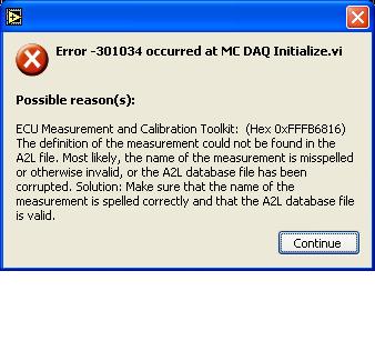
Error-301034 with Toolkit ECU Measurement and Calibration
I get a message error 301034 occurred at MC Daq Initialize when I try to run my program.
I checked my measure names are correctly spelled (special case) and the a2l file is a copy of one that is used on other testbed that uses sofa. I copied the a2l file once again and reinstalled but the error is the same.
I checked the CRO and DTOS and they are correct.
Any ideas what may be the cause?
Hello, AAM,.
You try to use a feature name in the DAQ initialize? You said that you got the error on initialization of data acquisition and the error indicates that the measure was not found... but you've posted a feature here...
Could you also make sure that the COMPU_METHOD_27 is defined in your A2L. It should be (something) defined as follows:
/ COMPU_METHOD COMPU_METHOD_27 to start «»
RAT_FUNC «6.2% ' «»
0 1 0 0 0 1 COEFFS
/end COMPU_METHODHave a great week.


Maybe you are looking for
-
Avoid Firefox 2 tabs opening on the first time
Hello For internal use at my workplace, we use a custom, FirefoxEverything is ok on the fact that the first time, opening custom Firefox on a PC,.When no profile folder is existing, firefox opens 2 tabs. And after that first time everything is ok, I
-
OfficeJet Pro 8615: HP Officejet Pro 8615
I have a problem when I print Adobe Indesign documents. I print a one page document. So if I print copies of mutiple (5 to 10 copies or more) the printer spits out a blank page all other pages. It is not the margin of the document because I have have
-
Ultra Backup 64 GB: how to restore files on a public computer?
Hello I recently bought a Sandisk Ultra Backup flash with a capacity of 64 GB drive. U3 removed, the software installed on my PC - everything worked well. Now, if I come to a public computer with my USB key, I can not install the backup software. So,
-
Create playlists of music already on the player in MSC mode
Let me start by saying to pretend I'm disabled mentally. I've never used a sync button in my life has always been Sansa and used to use MTP mode, right click in Windows, create playlists of pla and get exactly what I wanted. Now I have a zip clip and
-
My laptop (Windows 7) doesn't recognize CD or DVD when inserted in the drive.
Original title: CDs? DVD not recognized My laptop (Windows 7) doesn't recognize CD or DVD when inserted in the drive. No error message does nothing! ???