Use of DAQ in flat sequence
Hello!
I have a problem with my program.
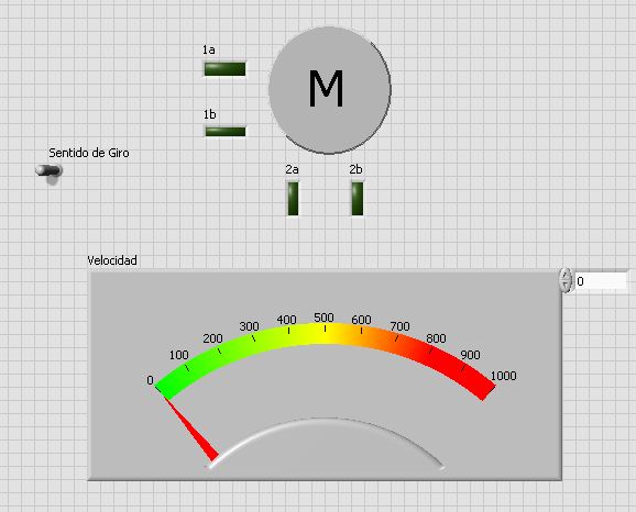
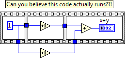
I made the diagram below. I pretend to control a bipolar stepper motor with data acquisition and a l293d, so I did the sequence
the coils requires with the plate sequence and structure of case extern just reverse sequences. It works as I thought, but,.
When I connect the daq 6008 apparently not to receive data. I think it's the sequence of plate, because I tested the daq with
another program with just a while loop and it works good sense.
Please someone explain this to me... Thank you!!
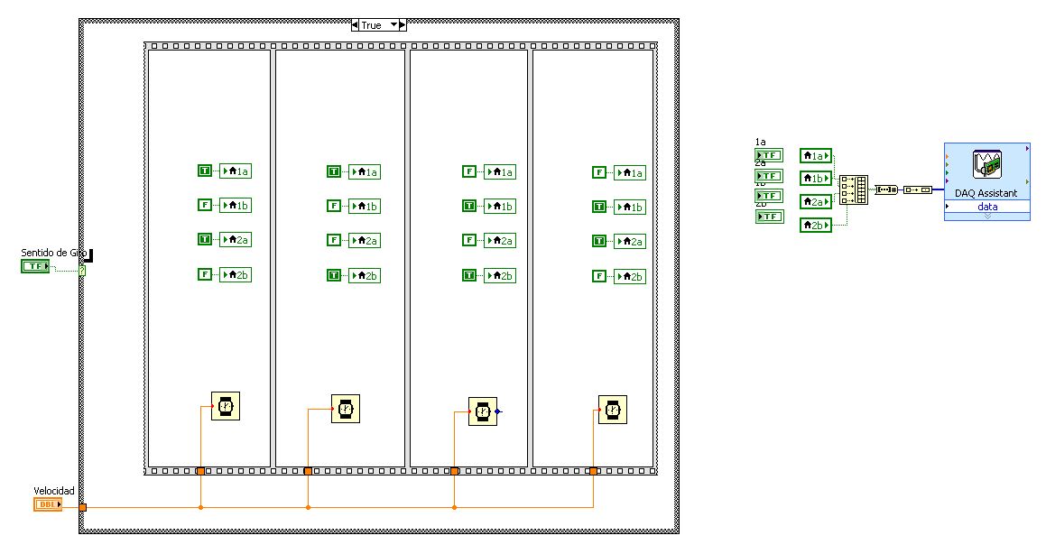
A race condition is a situation where two or more parts of the program can operate independently of the other and nothing in the controls of the program or the forces of the order of execution. In the image code you've posted local variables in the first frame of the structure of sequence may be run before or after those related to the DAQ Assistant. Of course the structure of sequence ensures that the local population in the 2nd, frames, 3rd and 4th will work later than the first image. That won't happen in reality but in principle the entire file + sequence casting structure run before the people of the country connected to the DAQ Assistant have been read. Then, you would get the last value onley.
To fix it, learn how to leverage the data flow. Create a 2D of the Boolean array. With the help of Autoindexing on a loop for, read one line at a time and it wire to the DAQ Assistant (also inside the loop). Look at the VI attached.
Lynn
Tags: NI Software
Similar Questions
-
The speed of the flat sequence?
Hello
What I want to do: read a map OR 6 analog voltages and provide a few analog/digital outputs from another card of NEITHER.
Here's what I do: I use the DAQ assistant to acquire 6 different analogue voltages on a simulated map of NI 9205. I tried to run at the same time all 6 data acquisition assistant acquires (which did not), but I read that since there is only a single clock on the map, so I can not use multiple acquires at the same time because of timing issues (right?). Then, I put my DAQ assistants in their own images in a flat sequence then they would be operated sequentially. This works fine, but each frame/acquire takes 1 second to complete. Which means that my program lasts 6 seconds to do everything acquires it, before my other code outside the plate sequence. Outside platform sequence are my trips (some digital and analog a bit on a slider). Because my flat sequence lasts 6 seconds to compete, my outputs are updated only once every the 6 seconds, where as before the flat sequence has been inserted that they have been updated little almost instantly.
Here are the questions: can I do the flat sequence run faster? Or is there a way to simultaneously acquire several analog voltage using the DAQ assistant. I feel that I shouldn't need to the apartment of sequences, but do not know a better way to go about it.
I hope that makes sense and I'm pretty new to labview so feel free to add many details.
Thank you!
PS: If you try my Vi, notice how slowly the 3 top entries in the page update, if I remove the huge flat sequence, they run very quickly and smoothly, which is what I would like.
e g m e n i wrote:
Here's what I do: I use the DAQ assistant to acquire 6 different analogue voltages on a simulated map of NI 9205. I tried to run at the same time all 6 data acquisition assistant acquires (which did not), but I read that since there is only a single clock on the map, so I can not use multiple acquires at the same time because of timing issues (right?).
Instead of trying to run 6 assistants for the acquisition of data in parallel (or sequential), use one assistant DAQ who reads all channels simultaneously.
-
Hi all
Basically, I'm in the order of many device and regulation for that pourpose, I created a sequence of plate to do. Also, at times I have start the potentiostat measures I use too, which follows a sequence and I created a second flat sequence to do this. In a part of my experience, I want to follow the voltage and current of high voltage power supply that is located in the flat main sequence and also read the results I'm getting with the potentiostat simultaneously.
In the main sequence, there is a constant bollean which triggers the beginning of the secondary sequence. In the framework after it contant Boolean, I have a while loop in which I read 2 analog inputs of the power supply high voltage with my USB-6218 for awhile every 100 m, my problem is that the Boolean constant actually starts the subsequence flat but when it reaches a while loop in which I continue to read the results of the potentiostat , for a reason that the operation does not start until the while loop in the main loop is not finished.
I communicate with the software of the potentiostat through a driver made by the manufacturer.
Is it possible to read analog inputs with USB DAQ and simultaneously read the results of the potentiostat?
Thank you very much
Without being able to see the code, can only speculate. My guess is that you have probably some data flow to the second loop that depends on the first loop finish.
-
structure of flat sequence for benchmarking
Hello
Maybe this is very obvious, but I don't completely understand something with the sequence flat structures-FSS (I never use this structure by the way and I don't you not why they use it in this example).
There's a doc OR online explaining some mistakes of rookie in LV:
http://www.NI.com/newsletter/51735/en/
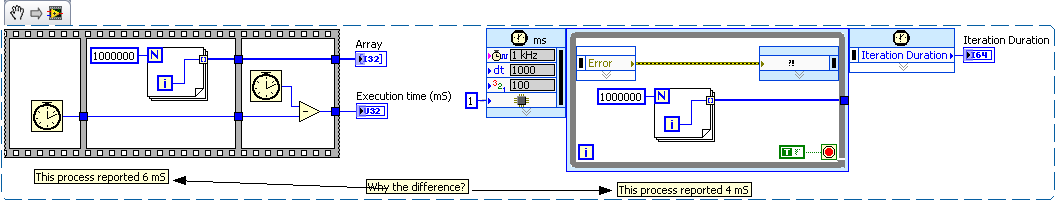
The doc has described that the FSS is useful for benchmarking, the BD:
My question: what if we put the number of cycles in a Subvi left and right and giving the exec. order with wires of the error? Or using a while loop that runs only once (with sons of error through)?
These 3 different ways are the same?
Yes, you can do all these things - I think that the only thing to keep in mind is that you do not want your benchmarking code to affect the speed of the code - otherwise, you'll get inaccurate results. If you use the while loop, you will need to do something to make sure your second number of cycles will run after your time loop - for example with FSS

Flat sequence structure using is OK - it's overuse of it which is a common rookie mistake - trying to force things to run in a specific order (for example if from a text based on the sequential programming language) instead of understanding that this is done by data flow in LabVIEW.
I think that the reason is simply because the number of cycles VI doesn't have an entry so you cannot apply data flow. It is common to have a Subvi, which encapsulates the number of cycles VI with error/output wire.
-
Front Panel does not (exactly 2 even while in flat sequence loop)? LabVIEW BUG?
Hello world
I have two while loop with exactly the same code and a user in each loop event structure,
They both make the same thing which is too run until IMAQ image control (one line) click on a recording.
I used a flat sequence to manage the order of execution.
The problem is when I use only one single loop (put another in a diagram to disable) the façade answer perfectly and the program does what it should, but when I activate the two loops stuck in case of timeout...
I do not understand what is happening that I can't do any activity of façade that would be registered, enclosed is a copy of the VI (you need NIVision run the vi).
Any idea? Is this a bug or did I do something wrong?
Thank you very much
Best regards
This isn't a bug, but the expected behavior. You cannot sequence structures event like this, they both need to be ready to react. Use a single event structure and a state machine architecture. You have about 4 copies of basically the same code of event management. Try to combine everything in one!
What happens in your case?
Answer: The two structures event will begin immediately queues of events, but the second event structure cannot respond to them because it is inaccessible due to data flow. In addition, the second structure of the event is set to "lock the front panel until the end of the event. Given that the event cannot end as explained above, the façade is locked up forever.
-
Delay the time of flat sequence Structure?
How to delay the moment of execution for flat sequence Structure?
Your question is a little vague.
You want to delay in a certain amount of time? Until something happens?
You can add a primitive frame with a wait.
It might be useful to you could reach a simplified example so that we can better see what you're doing.
-
Replace the flat sequence Structure?
I read a bit in the forum and a lot of people discouraged to use the structures of the sequence. Here's the situation: I have a tick count at the beginning for the iteration (and another at the end). I want to force them to count before (and after) anything else. The code I'm working on leash all data through structures flat sequences that contain only tick counts. Is there a different way that you can do without the structures of the sequence?
Thans
The recommendation not to use structures of sequence applies to most of the cases where people use. State machines are the preferred (and best) method. However, this does not mean that there is never a good use for a sequence structure. In your case, when you both want something, it is perfectly acceptable. An example is shown in the first snippet below.
There is an alternative however. You can use a timed loop to time your code. Someone posted here once an example. I forgot who he was and who puts in. It went something like the snippet of the second.
I would like to know why there is a difference in speed between these two methods:
-
In the case of flat sequence LED
Hello
I have 2 flat sequence event with 1 LED in each event. How can I turn on the LED when the start of the event and the OFF when the event ended before he will move to the next event.
Help, please.
Thank you
Those who are not in the sequence of events. These are individual images. Events in LabVIEW are something completely different. Based on your question it seems that you are not completely understand dataflow. A function/VI will run when all data on the cables connected to it is present. Stream can be used to enforce the execution order, but executives of sequence can also be used.
In your first picture if you wire a real constant for the Boolean value, you can control when the Boolean value is updated because there is no dependenct data between the numerical calculations and writing of the LED. So, if you want to turn on the front LED the first image, then you must add a frame before the first person where you set the indicator and the same thing at the end.
-
How to stop a flat sequence (or timed sequence) which is inside a loop for
The problem is this, I have a loop that repeats 10 times and inside this loop, I have a flat sequence (or timed sequence) with four images, each of this chassis to evaluate a different condition of a vector that I introduce.
What I woud like for example is:
I'm a fifth County of the loop for and in the case that part 2 does not meet the condition, the sequence of dish (or timed sequence) stops and starts the loop again but this time for the number of number 6.
I would appreciate your response.
You can't stop a sequence structure. This is how they are made.
What you should consider to get rid fo structures sequence and to change a state machine architecture. There are many examples in LabVIEW, as well as on the Forums. The big advantage of the state machine is that at the end of each State, it examines the conditions and determines which State then run. And that is exactly the description of the problem you are experiencing.
Lynn
-
Scripts (connect a Terminal to a flat sequence Structure)
(script)
Is it possible to connect a terminal to a flat Structure of the sequence? (in my case, with a single frame)
(with the "Connect Wire" method)
Ouadji wrote:
but the main question is... Why the flat sequence structure does not inherit from node?
Why the developers chose this?
What is the main idea of this choice?Flat sequence Structure introduced in LabVIEW 7.0, provides a semantic schema object that no other object has. It is a structure of multi-frame (like a case structure or a stacked sequence), but it is the only structure where data can be wired between frames through normal tunnels. It is the only structure which may have tunnels in places other than its external borders. It is the only structure that can have subdiagrams of different sizes in different positions. It also introduces scenarios of strange wiring that you won't find elsewhere:
At the same time that the flat Structure of the sequence was introduced, there was enough of these bizarre scenarios with scripts (which was an internal feature NOR at the time), it was easier on the developer to make his own script class to try to find a way to support it under an existing class. We had no idea that script would become a public service someday, so the burden was relatively low and limited within the walls of NOR. Looking back, there have been enough problems with the FlatSequence class in the script than most of us agree that it would be better to have it in class Node (or more precisely, the class MultiFrameStructure) from the beginning.
-
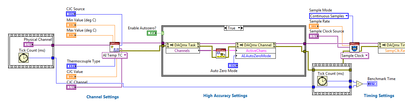
Using the DAQ USB-6009 meter and an analog input voltage at the same time.
Hello
Currently, I'm reading the two channels of voltage with the USB-6009. It happens that one of the channels is the output of a digital coder, and it would be much easier to use it directly to the PFIO entry that is defined as a counter. The problem I am facing right now, it's that I can't use the DAQ Assistant to use the analog voltage to a channel and the digital channel counter at the same time. Once I put the DAQ Assistant to read the input from analogue voltage, I won't be able to add analog inputs. And as I put the DAQ Assistant to use the PFIO as a counter, I can add more entries to read analog voltage is.
I wonder if it is possible to solve this problem using the lower level data blocks? Another solution would be to read two channels in analog input voltage and that the use of Matlab to process data resulting from it, since I was not able to do the counting to work simultaneously with the acquisition in Labview to impulses.
Hope you guys can help out me.
Thanks in advance.
Using a simple wizard of DAQ is incorrect. You need one to acquire analog inputs and one for the meter.
-
is it safe to use a view control of sequence to display the sequence file both for execution
I have a Teststand UI written in Labview 2012. It has a single control of sequence, and I use the ConnectSequenceView method to switch between the display just the loading sequence file and the running. Allow me to reiterate. When a file sequence is running, the control is connected to the execution Manager. Otherwise, it is connected to sequenceFileView Manager.
I begin to suspect that I have questions related to this control, when I do the following.
1. load a movie file
2 run Single Pass
3. the execution ends
4. unloading and Release sequence file
5 load a different sequence file
6. run single-pass
7 Labview crashes
Am I missing a step?
Thank you
Kevin
So it seems the crash of Labview, I mentioned in the original post is unrelated to the joint use of display of the sequence control. However during my troubleshooting, I noticed that I was missing cut from a point of view of control stage before connecting the other view.
And for the record, I think that there are many things wrong with the architecture used in the complete example, but there also many too many features for what to. Just need a simple "press a button" and "run a test" for operators. Everyone uses the sequence editor.
All right. Thanks for the comments.
Kevin
-
How to capture language settings by using the Sccm 2012 task sequence.
Help, please
I want to capture language settings by using the Sccm 2012 task sequence.
for example, if I push the task sequence on a computer through the software Center... He must capture the machine language first, and then format the machine and then restore back language settings... I'm not sure if USMT capture language using the task sequence settings... could you please help and let me know if any solution for this
Thanks in advance
This issue is beyond the scope of this site (for consumers) and to be sure, you get the best (and fastest) reply, we have to ask either on Technet (for IT Pro) or MSDN (for developers)
If you give us a link to the new thread we can point to some resources it -
How to create different types of analog inputs without using the DAQ assistant?
Hi all
I would like to create multiple entries multiple analog channels of type... I mean I want to have the voltage of 5 and 2 channels of temperature...
However, I am not using the DAQ assistant. I use "create channel" vi.
Can anyone suggest me please how to do / I submit my VI for reference... I have 5 tensions, and 2 temperature characterized as showing these 2 two separate graphics...
-
Conversion of a VI that uses OR-DAQ traditional to NOR-DAQmx
Hello
I'm trying to convert a VI that uses OR-DAQ traditional to NOR-DAQmx. I'm almost there, but when I run my new rear version number 'read' and 'scan' are not the same.
In the original version the "number read" always came back as 1 and "scan" backlog is always returned as 0.
In the new version, "number readings" and "rear scan" could come back with any value. It's sure to shake my recording of measures and VI the interaction with the rest of the program.
I have attached a light version of the VI for the old OR-DAQ traditional and new OR-DAQmx that illustrate this problem. The two VI is written in LabVIEW 2011 SP1. I would be willing to upgrade to SP1 2013 LabVIEW if it would help solve the problem.
I would be grateful for any guidance.
Thank you in advance.
I think I did. Use-1 to erase everything in the buffer when the program is waiting for the countdown to the end and then just ask for 1000 measurements when the countdown reaches 0. Do not need the Scan back or number reading. Also don't need to add the measure in table 1 at a time because I get them all at once.
I enclose a copy of my solution for all those who might need to do something similar in the future.
Gary
Maybe you are looking for
-
How to export multism to matlab
I need to export matlab multism (the op amp output) signal to calculate SNR
-
Hi all I am considering buying the t430. The only problem I have is that I live in the Canada and I would get the AZERTY French keyboard instead of the french CSA or the french Canadian QWERTY keyboard on this subject. Anyone know if it is possible t
-
How will I know what form a table is a long section of the mathscript code? IE is a table one row or column, or a matrix. Often, I get the error that produced the home, regardless of what form, I develop controls in. I really need an accurate way to
-
connect to hp 2540 wireless to linksys WAG200G router
I try to connect the HP DESKJET 2545 to the Linksys WAG200G router via the USB cable and the HP software. The software detects the router and the parameters (name SSID and password) but finally when it tries to connect, it says that the name of the n
-
HP Pavilion M6R61EA #ABU: HP Pavilion connection to external monitor
I want to display photos from my computer on my TV. The TV came while the HP Pavilion Notebook only has a HDMI RGB connector. I bought a cable to connect the two. The TV screen works perfectly for 20-30 seconds and then there are the red lines on t