USRP
Hello
I'm try the loop back test with USRP2920
I use the example of finishes synk RX TX VI
but the signal still has a different phase
How is it possible?
Hi valerio
I solved the problem... Thank you for the interest.
Francesco
Tags: NI Products
Similar Questions
-
Device unidentified USRP 2921 (not listed is not in the utility of Configuration of NOR-USRP)
I connected with my PC (ethernet end) NI USRP 2921. I'm trying to use it with Labview 2015 64 Bit/2013 32 Bit. I also installed the driver NI USRP 15.0
My USRP powered on correctly. It is also detected by my PC, but it does not identify its USRP and rest unidentified network.It does not appear in the NI USRP configuration utility.
I also put a static IP address for my computer.
Kindly help.Hi lmdadinho,
Since your 2921 USRP powered and is detected, this looks like a problem of network as a problem with the 2921 more of himself. The Getting Started Guide (http://www.ni.com/pdf/manuals/376358a.pdf) has some network troubleshooting to try, beginning on page 12. This could be a good starting point.
Best,
-
I'm new on USRP and I have a 2901 I'm trying to control with a C program. The manual says the device can be used only with Labview System Communication Design, but all the drivers seem to be there. Can I control with C program? If I can use with the C program, should I install the Labview anyway?
C I can communicate with the device, but after I niUSRP_ConfigureSignal and call niUSRP_WriteTxDataComplexInt16 to send samples, the call to fail with the message "data NI2901 writing failed. Status =-1074118650 ", even if I have the time set for a certain number of negatvie (wait forever). All other calls seem to work perfectly. Any help would be appreciated.
Hi Phipps,
You can program the 2900 using the driver Ettus UHD in C++, and I think that C as well. The USRP 2900 is very similar to a B200.
-
Time Division Multiplexing (TDM) Using USRP s 2943 with synchronization
Hello
I have two 2943R USRP. One of them is transmitter another is the receiver. I wonder about the moment on USRPs division multiplexing. How could I implement this system? On the first slot of the Trasmitter USRP channel 0 will send the signal, receive USRP channel 0 will get the signal, on the second time slice Trasmitter USRP 1 channel it will send the signal, receive USRP channel 0 will receive the signal again. This process will goes in the order. So in detail, Ch0 of USRP0 will send the first niche hourly Ch0 of USRP1 will receive, Ch1 of USRP0 will send, Ch0 of USRP1 will receive again after the third slot Ch0 of USRP0 will send the signal. This process will be contiue until I stop VI. Signals will be displayed on the receiving party and release will signal where USRP0 Ch0 and Ch1 USRP0. Example of synchronization is present on examples of NI Labview 2014 USRP on PPS trig. But I could not find example vi or a document on the TDM with synchronization. You give me advice? How could I overcome this problem?
Best regards...
Hello again,
I found an example on the community or my research: https://decibel.ni.com/content/docs/DOC-23677
Can I use this paper for my purpose? Is this useful? Could you give me advice please?
I don't have much experience on 2943R. I am trying to learn... How could I change this document for my research?
Best regards...
-
Question about USRP synchronization when using 1 X 2 MIMO
Hello
I wonder section about 1 X 2 MIMO (a transceiver system two USRP). I entered sequence of bits as "10101010...' part of the transmitter." If '1' and '0' bits are aligned in order. 0 comes after 1, 0 just after 1. I want to send this sequence of bits of the USRP transmitter to the channel. On the receiving party; How can I set the time and implemented receiver USRPs triggers that one that USRP will get only 1 bit of these when other USRP will pick up only when thise 0 bits. How can I synchronize this MIMO 1 X 2 like this system? Could you give me advice?
Best regards.
Hi ahmetemir,
I think that this example will provide a framework for what you're trying to do: https://decibel.ni.com/content/docs/DOC-23677.
-
NI USRP 2940 R safe mode button
Hi all
I have a NI USRP 2940 R, which is unreachble via ethernet (1 Gb) after a firmware change.
To change the firmware, I used the following command:
uhd_image_loader - args = "type = x 300, addr = 192.168.10.2"--fpga-path="/usr/share/uhd/images/usrp_x310_fpga_XG.lvbitx"
The procedure seems to be successful:
-Initialization FPGA... successful loading.
-Image of HG FPGA loading: 100% (areas of 121/121)
-Finalize loading image... successfully.
Turn on the USRP X 310 to use the new image.But after the power cycle, I can not able to ping of the USRP and also orders uhd_find_devices and uhd_usrp_probe say 'No UHD Devices Found'. So I thought I would put my NI USRP 2940 R in safe mode.
In the "GETTING a STARTED GUIDE NI USRP-2940R/2942R/2943R universal software Radio peripheral" (http://www.ni.com/pdf/manuals/375717f.pdf) in the section "why isn't the default Reset IP address?", I found the procedure that says to locate the pushbutton switch (S2).
The problem is that unlike OR USRP 2920 wherein the S2 button is easy to reach, I could not find button SafeMode in NI USRP 2940 a. I have found that the buttons SW1 and SW3.
Anyone has idea about what are the keys SW1 and SW3? Or better, how to reset the USRP NI 2940 R?
Thank you very much for your attention.
Best regards.
Francesco.
Image usrp_x310_fpga_XG.lvbitx implements only 10GbE SFP ports, so you will not be able to communicate with the device via 1GbE, although it is charged. You need probably the image of usrp_x310_fpga_HG.lvbitx which has a single port to 1 GB and the other to 10 GB and is the image that the devices are provided with. See https://files.ettus.com/manual/page_usrp_x3x0.html#x3x0_load_fpga_imgs_fpga_flavours for more information on the different FPGA images available.
There is no safe mode on the USRP AND 2940R, but there are different ways to load a new FPGA image that will work without a functional image already on the device. The PCIe connection on the device may load images temporarily in the device and update the image in flash even if there is no image already on it. USB JTAG connection on the front panel can also be used to temporarily to load a new image so that you can access the device via Ethernet to update the persistent image. Also, you should be able to use the unit normally if you have a connection with the 10GbE. The above linked page includes directions for all of these methods of loading images.
-
USRP 2920 if after joint bottom (after the MIXING table)?
Salvation _ or
the NI USRP-2920 is a good product I use it to train students on some applications
I read manual for this product its especially usfel and covering a large part of the specs of the device, BUT "nothing mentioned about.
Central frequency (IF).
"to clarify my question" when the signal down mixed RF is it wil be centered arround fixed frequency for demodulation processs "its about 12.5 MHz in one of the device NOT USRP"
What is the center frequency of the baseband signal after mixed down?
I wish I can explain my problem, iam waiting for your answer, answer or tell me you want more explanation on what I want now...
Thank youIt is a direct down conversion device. RF is mixed with the baseband quadrature I and Q. There is not SO.
-
Surveillance of the spectrum with USRP 2920
Hello
I see all the examples on the analysis of the spectrum
but nothing is near my desired app cause
as an example https://decibel.ni.com/content/docs/DOC-40721
It uses an entry 'carrier' and then show spectrum
I want to start and stop frequency within the bandwidth instantenous 2920 USRP
and monitor the spectrum in the band of desierd
I want signals to show their real carriers not baseband signal after demodulation
Thank you
Hello
Can you explain a little more about your use of the application? Frequency range you want to monitor? So, can you explain why you need to "show the signals to their actual carriers and not baseband? The USRP 2920 has only 40 MHz of instantaneous bandwidth (and only 20 MHz with a resolution of 16 bits) so unless the signal of your 'real' sitting in the baseband already (i.e. below 40 MHz) you would be sewing together the spectrum required for an acquisition to wide band and he would not be instantaneous.
Kind regards
John Gentile
Engineering applications
-
LV 1.1, 14.5.1, 2950R USRP, DSP overflow using the example of Streaming Single-Device
Hello.
I use the SDR LabVIEW 1.1 and the USRP 14.5.1 with USRP-2950 device driver. Recently, I tried to use the interface of RX-host of the 'USRP RIO 40 MHz BW Single - Device Streaming PC' - example. Although the USRP device is connected to the PC via the MXIe card I get an error of overflow DSP (continuous mode). In my view must avoid an overflow of DSP for the chosen bandwidth and sample rate (examples in screenshot).
If someone else gets this error or do I have to contact support OR? I already crushed the FPGA Image with the "NOR-SURP Configuration Utility.
Thanks and greetings
-
Synchronize several USRP using Octoclock
Hello community!
I'm trying to synchronize several Ettus USRP N210 using Octoclock. I send you a short tag to a USRP to each set second (using the timestamp on board), the other USRP choices until the tag and display the time. I put the clock at PpsIn two USRP source by using the node properties of niusrp, but it seems the two USRP to use even their internal clock: I see a fraction of a second relatively fixed the RX once it picks up a lighthouse and this fraction of a second does not change if I put the clock to internal or ppsin source. I don't know if this is the correct way of sync USRP external reference because I'm quite new to Labview Comms, anyone have any ideas? Thank you very much!
Hello Maxcy,
Welcome to the community!
I highly recommend looking through aid NOR-USRP > Programming Reference > document MIMO synchronization. This will help you understand the synchronization.
Synchronization requires two components, a shared time base and trigger to start. In this case to share the time base, you use synchronization and synchronization of the USRP properties reference to set the frequency to RefIn reference and the Source of the time base to be PPSIn. You will need to wire the system as Figure 9 in the following Document Ettus:
http://www.ettus.com/content/files/KB/mimo_and_sync_with_usrp_updated.PDFIn order to share the relaxation from the beginning, we want to use the time to start to set up to be in 1 second increments. More important, you want to reset timers USRP onboard all USRPs at the same time. This is done using the Set Time VI and ensure that the change is applied to the next edge PPS (together the entry timestamp apply 1). This will require the TX and RX both be started and configured in the same second on the other. For testing purposes, I have recommended to configure the RX and TX within the same VI. This will benefit of innate parallelism of LabVIEW and ensure that both are started at the same time.
With synchronization, above all there will be a random amount of phase constant offset between the channels, as shown in figure 6 of:
http://www.ettus.com/content/files/KB/mimo_and_sync_with_usrp_updated.PDF
This could be responsible for your consistent fractional offset. These needs to be processed signal to ensure alignment.I hope this helps.
Kind regards
-
SISO TDD OFDM Streaming Video on NEITHER RIO or FlexRIO USRP
Hello!
How has the Full Duplex was assured in USRP RIO?
In accordance with the document of this example, the simultaneous transmission of receiver chain is possible at the same frequency. If I take this right has component the interference of the transmitter Tx1 and RX1 was completely canceled for transposition Full Duplex.
Or the FD is possible for an arrangement of the antenna?
Thank you
Understood that here Full Duplex doesn't mean full-duplex, we speak in reception and simultaneous transmission of documents i.e. contemporaries. Here, it's a TDD system, where two data sources can be listened in conjunction, rising and falling, for example as in the No. loopback condition. Simultaneous, albeit two multiplexes in time, flow: downlink uplink (base station user) (base station for the user).
-
Cannot create the multi channels Tx two USRP-2943Rs Session with driver
I have problems of implementation of several USRP-2943R devices in tranmist both of their channels at once. Right now my configuration is a configuration of four chains composed of two devices of RIO. I am only able to transmit at the same time successfully CH0 and CH1. I'm creating a session using two devices and my aim is to perform Tx on CH0 via CH3. In addition, my goal is to use the LabVIEW driver without any synchronization, because I test fix synchronization through post-processing and you want the VI be as simple as possible without the hassle of FPGA programming. I realize has the Simple models OR - USRP Streaming Sync in LabVIEW, but additional synchronization and FPGA programming is too much for such a simple project like mine which would require no synchronization USRP.
My VI and some screenshots of the error messages resulting is attached. I am able to succesfully implement multi-channel Rx deals and attached is my multichannel Rx VI. My question is why I can open and operate a session of Rx mult-channel without problem, while a multi-channel Tx session will give me errors?
My final goal is to merge my multichannel work Rx VI with a mult-channel Tx VI work for measurements in order to test some synchronization post-processing routines that are performed in Matlab.
I think that I found a solution to my problem. I thought to post it here to help others. It is important to use some sort of device to synchronize several USRPs. However. I found that you must reset the device by setting the node of reset function blocks that open and session Rx or Tx. "" If it is not defined, then the ' niUSRP Signal.vi configure
the ID of the specified attribute is not valid for the scope specified (or channel). " error occurs, any circuits that you define. After the node Reset true and place an empty string for my channels Enabled, all was fine. Also, a full duplex system you will be only to first log of Rx with a reset of the device, followed by the opening of a session of Tx without a reset of the device.One more thing, it is that there seems to be a bug if you feed a Tx process a table whose number of lines does not match the number of channels Tx. This will result in weird errors funny will disappear only after doing a hard reset of the units. So, just something to take note of.
I hope this information will help others and this message can be marked as resolved.
-
Muliple USRP RIO 2943R, synchronization and phase-locking problem
I use 8 USRP RIO 2943Rs transmission of signal and receving (4 for Tx) and 4 for Rx I'm using the "signal-based" method for synchronization of all devices. And I did it. I tested the system the result is very interesting:
1. when I put the sampling rate of less than 40MS/s IQ, I can obversve very good phase locked Tx and Rx signals (I use a sine wave CW for tests), please refer to video joint (locked 40MSs)
2. BUT, when I put the IQ more than 60 MS/s sampling rate, I'll lose phase lock. Please refer to unlocked 60MSs. My goal is to run the system at 120MS/s
I have doubt as to if the problem comes from two sides:
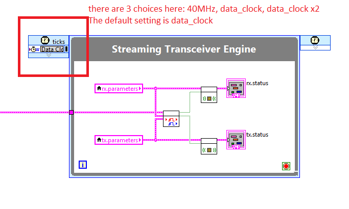
a. the sync methed isn't fair
b. OR, should I increase the clock that operates the loop 'In Streaming radio engine' in the FPGA VI. as shown in the following image.I would like to ask experts in the forum to discuss the solution of this problem.
More information about my system setting:
-
Problem of generation of Sync trigger in several synchronization USRP RIO 2943R problem
Generation problem shutter Sync in several synchronization USRP RIO 2943R problem.
Previous SR you may already know I'm stacked in USRP RIO multiple synchronization problem, especially in the mode based on the signal. Now I can cut down, the problem is mainly due to the outbreak of sync signals generation.
First of all, I read the article and the discussion in the following two links:
http://forums.NI.com/T5/USRP-software-radio/how-to-synchronize-multiple-USRP-Rio-294x-devices/TD-p/3...
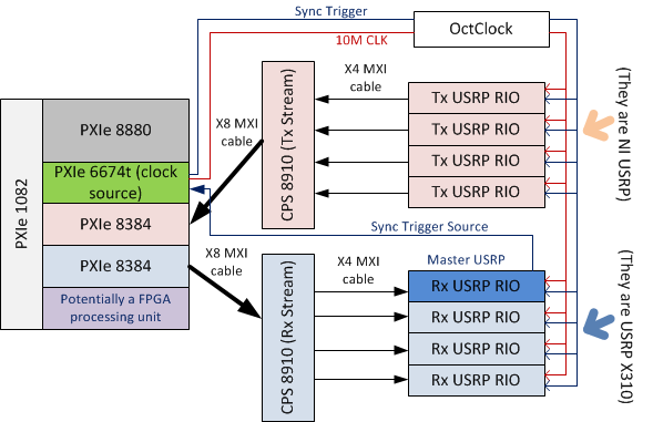
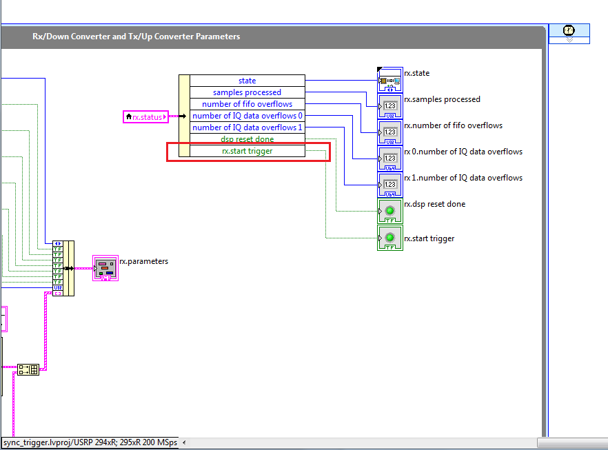
http://zone.NI.com/reference/en-XX/help/373380D-01/usrphelp/synchronization/and I did my connection of the material according to the suggestions in the second link. My system schematic is shown in the following image:
I checked OctColck and SMU 6674 T connections. They are all connected correctly and the cable are fine. I use the niUsrpRio200_XcvrSyncPps.lvbitx.
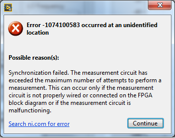
According to the description of documents and discussion forum, the USRP RIO 1st in the list of devices are considered to be the USRP Master. Then, the FPGA to master USRP RIO released "trigger of sync" signal through the 'PPS Trigger Out' SMA port in RIO USRP box.
Based on the my analysis of the system, the first impression I have is the USRP Master does not export the 'sync trigger' correctly. The host VI reports the error like this:I was trying to measure the "synchronization trigger" using oscilloscope, but I found that it is impossible, because the host VI can not yet run, so there is that no signal can be seen from port 'PPS Trigger OUT.
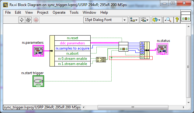
So I think that if I can watch this signal "sync trigger" in home VI by importing this signal from FPGA to host VI. I did some changes on the FPGA VI as shown in the following image to watch this signal of façade of the host VI. but not so successful. the rx.start tragger relaxation and tx.start do not appear on the host vi read/write control function.
-
I want to use NI USRP 2901 with gnuradio.
I looked and I found that I need to update the firmware and FPGA image.
I found these instructions for the NI 292 X
http://digital.NI.com/public.nsf/allkb/F622E3B3B9CC34B6862579D500705272
What are the equivalent instructions for the NI-2901 (connected via a USB ethernet port not)?
Where can I get the FPGA image and firmware?
It turned out that the UHD version I had was old, I've updated my UHD version for later. It is automatically loaded the correct image of FPGA and firmware. Now she I even works great with gnuradio.
Thank you.
-
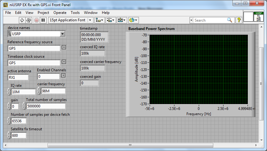
Acquisition with USRP 2953R of the GPS signal
Hi all
How can I configure a 2953R USRP receive GPS signals? I have an antenna VERT900 connected to the GPS ANT of the USRP port, but in the example VI 'niUSRP EX Rx with GPS', I can't reference this port in the field 'Active antenna'. I put only things like TX/RX or RX1 etc. Should what values I put in other areas as well? I know that the L1 band is 1575,42 MHz.
Hello
The example you posted shows you how to acquire an RF signal on the ports of the USRP with internal clock RF and sources of reference defined in the GPS.
To make it work properly, you must have a GPS antenna connected to the Terminal on the GPS device and installed in a place that receives a good level of GPS signal.
The other control of antenna on the schema defines the port on which to receive the RF signal.
If you want to capture and analyze the signal GPS (RF) itself, you can tune into the front-end RF (carrier frequency) at the right frequency of GPS band and connect your GPS antenna to the RF port.
You can use the simple niUSRP EX Rx continuous Async.vi in this case (but may not work due to the very low consumption of GPS RF signal)

Maybe you are looking for
-
installation on Android 2.2.1 Samsung Galaxy Ace 5380
Samsung Galaxy Ace 5380 Android 2.2.1 but can't install it because the store Play says your device is not compatible. Help, please!
-
Install Win 7 hangs after "install updates" starting windows
Re-installing win7 Professional 64 bit on a computer hp laptop. You had to make a record of killing to eliminate the problem. Previous installation went smooth. All files transfer and expand, all the way to the installation of updates. Then it coun
-
Black photo HP Photosmart 7520 printer refill cartridge missing color
I bought 564XL charging that color cartridge but was missing black picture? Bought at the Sams Club. Included in the package 3, cyan, photo 5 paper colors x 7, magenta, yellow and 25 and 10 envelopes. (Note: up to 2.5 X MORE than pages with XL) Pr
-
HP Photosmart C410a: printing test page but nothing else
Our printer wasn't working at all, so I uninstalled and reinstalled. He immediately printed the test page, but when I tried to print from Word, it does not print. It works through the sequence, is the impression that it appears, but the page comes ou
-
update of firmware for ofcjet 8500 power print from the ipad
I want to be able to print from my iPad 2 since my 8500 office jet all-in-one wireless