V5 output to the HDTV
I'm reading my V5 slides and videos on my HDTV via the HDMI port. The TV receives no signal. What I am doing wrong? Thank you.
The computer detects the second screen?
1. try to use different Port HDMI TV
2 different HDMI cable.
If you get the message as no signal also try to reinstall the driver of your computer display. See you soon
Tags: Acer Laptops
Similar Questions
-
How to change the audio output for the metronome
Hello
I would like to send the metronome (and speech signals) for monitors to the scene in the ear.
I understand that I can do this in MainStage using different output for the above titles vs. the rest of the 'Concert '.
I tried to follow the instructions of the Manual:
Change the audio output for the sound of the metronome
- Choose the MainStage > Preferences > General.
- In the section of metronome on the general tab, choose another audio output on the shortcut menu to exit.
PROBLEM
1. on the general tab, only the outputs 1-2 are available/selectable (likely, these are also by default for all "Concert")
2. Why is this process in the manual if it is not executable (without doing something to another additional Set up)?
3. it's probably among the requirements of setting up more critical even easier for using MainStage with a live band, so why am I having to ask for help at all!
Rant on (its been a long day)
Grateful for any help to solve cela. I guess I can send the metronome (such as a click track) and speech signals on the same outputs, which are separated from the rest of the Concert... or should I change the outputs on the other tracks and keep the outputs 1-2 for the metronome marks / voice?
Thanks in advance for all advice and my apologies for my frustration. JM
To access the output audio, you need an audio interface with several outputs.
-
Satellite Pro A100: No output on the monitor - Linux Suse 10.1
I'm trying to install SuSe 10.1 on my laptop and I get no output on the monitor. What is the provider to monitor and model?
Hello
Do you mean the monitor or the graphics card?
As far as I know the laptop was delivered with ATI MOBILITY RADEON X 1400 graphics card; ATI MOBILITY RADEON X 1600 128 MB and 256 MB of video ram.In addition, as far as I know it was delivered with screen 15.4 "(1280 x 800) color screen wide display TFT CSVI." I think that the seller is Toshiba
-
Tecra A10 with replicator - no output to the DVI port but analog works very well
Hi all. It's driving me crazy. Brand new Tecra A10 with a nine port replicator and a new external LCD. When I plug them all in all and connect to the screen using the blue/analog/d-sub cable, the image on the screen of the laptop automatically turns on the external screen when the A10 is docked. But when the external display is connected with the white/digital/DVI cable, the Tecra and/or the Replicator is auto-switch the output to the external screen.
In addition, when you press Fn + F5 to switch the LCD only to LCD + CRT or CRT output only, the Tecra is so "smart" as to "realize" there is no screen, and it switches the output to only the Tecra.
Now, we would put in place with the blue/analog/d-sub cable, but the picture is wavey and not satisfactory at all.
Just so we're clear - when the display is plugged into another computer, there is a beautiful clear picture on/through the white/digital/DVI cable, so I don't think it's screen.
Can anyone help with this please? Is the Replicator defective? Or am I missing something?
Thank you very much
As the portable Akuma (graphics card) does not have a DVI output.
If you use the VGA cable, but image quality should not be worse as with the DVI cable.
Choose the display resolution higher than the monitor supports and 60 Hz. -
Output of the front speaker left is almost a whisper
Hello
I had a Pavilion m9300t for over 3 years and I have always used a set of two simple speakers, attached to the headphone output on the front panels until recently when it is installed a system of 5.1 rear speakers using 3 ports on the Panel to find that the release of the "out front" seems to be the reason for all my troubles. I tried to go around the speakers and even checked the speakers on a machine and all seems to work well. "So I thought that all output ports provide stereo output, except the lime' out front speaker" on the rear panel. I have checked the drivers and all settings in Realtek HD Audio Manager and ran the tests of speaker and even used disseminators of media, but the front speaker will provide only a weak sound. Does this mean that his is a hardware problem and if she makes a bad port what are my options?
Thank you
MODI
Hi Modi,
Is the speaker that branch to the green port 'active '? I mean,'s done it this speaker has its own power supply plug or is connected to other stakeholders who have their own energy source? The green port on the PC is not "powered" so it only will provide a weak signal and expect the speakers to control the overall volume.
Something else to try, if you unplug all the other actors and simply plug the speakers into the green port, is the change in sound level? Alternatively, if you connect the headphones to the green port, you get audio normal?
This will help you determine whether or not the hardware works.
Another thing to try if you don't have it already: when you updated the audio driver, do you have the driver directly from Realtek, or did you use the HP driver? If you haven't tried the latest driver from Realtek, you can do it. Here is a link to download Realtek: http://www.realtek.com.tw/downloads/
Just select "High Definition Audio Codecs", accept the agreement and then download and install the driver for your operating system.
I hope this helps. Let us know how it goes.
-
No output on the e/S of NI5761
Trying to get an output on the connector of the PFI (to the e/s) of a 5761, but it does not work.
The NI5761 is connected to a high-7975R.
The four bits higher IO to the are defined to the outputs by sending 0xF0 'IO Module\PFI write enable' and 'IO Module\PFI connector activate' is set to true.
When I send 0xF0 'Output IO Module\PFI' the four upper bits should go up, I guess.
Nothing happens (I don't see any change on my oscilloscope).
I can read data from the four lower bits.
What I am doing wrong?
Hi Kees_D
Take a look through this post on the forum - it may be useful:
Please try to set all 8 lines DIO as outputs and see if you can write them that way.
If this does not help, please include screenshots or your code.
Thank you
Amy
-
Synchronization of analog and digital output with the external sample clock
Hello
First of all sorry for my English, I will try to explain what I want to do.
I want my PCIe-6321 to send two custom signals (modification sawtooths) on a mirror controller. I would also like to generate output with my card at the beginning of each tooth of saw. Everything must be synchronized with an external k-clock signal of 100 kHz. The idea is that whenever the PCI receives a trigger to external clock, it sends two analog output voltages and when he received 1024 clock ticks it will also send a pic of triggering TTL. What I do is first prepare the map and after that in a loop sending and modifing the output values of the two signals and at the same time send a digital signal Boolean in each arch, so when's done it 1024 iterations of the loop I send an event to the digital port. Attached you can see.
The problem is that I don't know how to synchronize both. Can I use the sample clock just to the analog output? I can use sample for the two outputs clock, or do I need to use the output of the meter? If don't know how to use it here.
If I do nothing else bad/wrong, I would be grateful for feedback.
Thanks in advance,
PabloI don't know how but I find the solution. I'm generating more than a positive value (as I was triggered maybe very fast the oscilloscope has been absent there). If I put the sample clock of digital output to use the sampling/ao/Dev1 clock that it doesn't, but if I put to use the same source as the OD (terminal where my external clock is connected), but the trigger to start the DO to be Dev1/ao/StartTrigger this works. I don't really know why, but it does.
Thank you for your patience and your help. I put here the final code.
-
How to make connections on the outputs of the letter of wsn 3202?
GOOG morning engineers,
How to make connections on the outputs of the letter of wsn 3202?
Sorry, I'm very confused by your response.
You must not something on the power set by program, just connect a power supply to DIO power and mass of DIO. Then your DIO lines should be able to output values.
In addition, I think that you may need to configure the output line. This would be by the project. I don't remember what it is, but it should be in some menu properties (probably for the specific line of DIO).
-
Output of the model to the user of controlled output
I have a simple model acting on AO1 of my system that generates an analog output of material on channel 1.
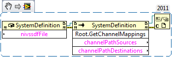
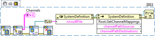
Sometimes I want to stop the model (no break, but stop) and a user interface acting directly on the AO1 via a control. For this, I use the Value.vi of single channel defined in the API Veristand. The channel is defined as targets/HILRT2/material/chassis/DAQ/Dev2/Analog Output / AO1 (1), as it should, in my view, but for some reason, the
It is not generated output...
Outputs from the model are also connected to target/HILRT2/material/chassis/DAQ/Dev2/Analog Output / AO1 and I wonder if (1) and (2) are not not incompatible...
Somehow I would like a way to easily change the control to a particular production of a GUI control of model output, or get the model of the road if necessary.
L.
PS: VS2011, LV 2011
I see.
You can use the definition of system API call 'get the mappings' for a list of mappings.
If you don't know what sysdef is running, you can use the API to run, call to get the State of the system and even to get the available channels.
-
DAQmx: Analog input directly to the analog output at the hardware level
Hi all
I searched for a while, but I couldn't find any suitable implementation for what I'm trying to do. A person where I work introduced me to an interesting challenge. Is there a way to set up a DAQmx task (or set up otherwise an MIO Board) to route an entry directly to an output to the analog analog hardware level? You may be thinking, "why the hell would you do? To reduce the electrical complexity, a colleague would like to concurrently read an entry while 'reproduction' of its signal on analog analog output. I know that I can easily accomplish this while the buffering by the PC, but they are interested in ensuring that the output signal is also similar to the input at the level of KHz signal, by introducing a minimal difference in phase (shift buffering of the PC).
For the record, we have for most old maps of the E series here like the PCI-6070E (PCI-MIO-16-1). I was first asked if it could be done through SCXI, but I figured I would start by asking about the MIO tips.
This looks like a long shot, and I've never heard of someone at - he never did this, but I thought I'd ask to be sure!
Thank you
Jim
Hi Jim,.
With the help of our driver is not a means of generating data directly from the FIFO of AI, it must first pass through the software. You can try the following code to the output of one of THE duplicate on the AO line to see what kind of delay you can imagine. It is similar to your original with a few adjustments code:
Use delayed output Version of avian influenza in DAQmx AO
It seems you need to do, you might consider instead the search by using a voltage follower to isolate the Vout wine.
Best regards
John
-
Configuration of the analog output of the controller PCI-7358
Hello world
I work with the PCI-7358 during a period of time and now I need to configure the output of the controller for a specific purpose. All I have to do is turn on and turn off the output to an analog 5V DC voltage level. I use a UMI-7774 as a breakthrough. I plugged the IO of 5-8 to the UMI axis MOVEMENT and I hope to get the tension off-axis 1 of the UMI CONTROL block. I use DAC.vi to load to turn on and off this PIN on UMI. When I tried the voltage level was 1.5VDC and it fluctuates so I tried to read the voltage on the PIN and she was 3.2Vac. It was said in this DAC.vi of charge help offset values or front torque limits does not affect the level of tension. I can't understand what is to limit the output voltage level. (I tried the 32000 and-32000 for entry this .vi)
If anyone can help urgently, I will be grateful...
Gencer Genç
Hi Roman,
in MAX, you must configure the axis as the stepper motors. You don't have to worry about the type of comment. You can leave this set to "encode". You can configure the engines loop Mode step by step in the tab settings of the Stepper to open loop. But in fact your needs, no matter, if you configure open-loop or closed-loop axis. Any mode stepper will be unmap the CAD of the axis.
In LabVIEW, just use ' configure axis resources "and map of the main output of your axis of stepper output or 'None '. This will also unmap the CAD of the axis. The secondary output must also be mapped to 'None '.
I hope this helps,
Jochen
-
power output of the spectrum in table
Hello
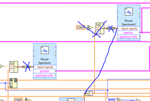
I have a signal and I need to make the power spectrum. How can we separate the information contained in the output of the power spectrum cluster? I tried to use the unbundle, but it gives me an error: "the type of the source is table 1 d of the cluster of 3 elements. The sink type is cluster of items 0 "if I click on the unbundle it won't let me select anything, it says empty..." Does anyone have an idea how to solve this, please?
Array of generation is not your friend here actually I replace the generation arrary and the screw Express Power Spectum with 'FFT Power Spectrum and PSD.vi' search the palette or use quick drop to locate him.
Why shoot there since just filtered signal to rebuild the same waveform? Wire the waveform to the second power of DSP and FFT spectrum .vi directly

-
How can I configure analog several outputs at the same voltage
I need the same voltage to 14 different outputs analog output. The only way I can think of that is shown in the attached image - IE. build a table. With 14 this looks messy - can you imagine how it would look with more! Is there a more orderly way to do this?
Dave
Hello
you want the same voltage setpoint for all channels so u 'initialize the array"give the dimension size you want, I think this will help u
-
Output analog, the USB-6009 case - can I use DAQmxWriteAnalogScalarF64?
I just got a NI USB-6009 and I try to use the outputs analog simple.
I'm running on a Mac, so I'll try to use the API OR-DAQmx Base 3.2 C (downloaded from here: http://joule.ni.com/nidu/cds/view/p/id/1078/lang/en). This is the most recent version of NOR-DAQmxBase, I could find.
I try to do continuous analog output on the 6009, which does not have a built-in clock. I was hoping to do the sync software and just new output values when I want to.
I can't get an output of database to work. Other messages and the example of Windows files, (e.g., National Instruments/NOR-DAQmx Base/examples/ao/MultVoltUpates-SWTimed.c) it seems that the best thing to do would be to use the DAQmxWriteAnalogScalarF64 function.
However, this is not in the Mac version of the C API of NIDAQmxBase. There is actually an entry for this in the NIDAQmxBase.h file, but it is commented out. Anyone know why? Is it possible to use this function for the analog output on request on Mac?
Thank you.
Clement
I have NEITHER-DAQmx Base installed 3.2 on a 10.4.11 system. One of the examples files 'genVoltage.c' calls DAQmxBaseWriteAnalogF64. I was able to compile and run this example with a USB-6009.
The DAQmxBaseWriteAnalogF64 function would work for you?
My guess is that, since you can write a scalar value with DAQmxBaseWriteAnalogF64, DAQmxBaseWriteAnalogScalarF64 becomes superfluous. The example provided with the installation shows how to write a unique value (i.e. scalar.). I pasted the code of OR below.
int main (int argc, char * argv [])
{
Task settings
Int32 error = 0;
TaskHandle taskHandle = 0;
char errBuff [2048] = {'\0'};
Channel settings
Char [] = "Dev1/ao0" chan
float64 min = 0.0;
float64 max = 5.0;
Sync settings
uInt64 samplesPerChan = 1;
Writing data parameters
float64 data = 3.25;
pointsWritten of Int32;
float64 timeout = 10.0;
DAQmxErrChk (DAQmxBaseCreateTask("",&taskHandle));
DAQmxErrChk (DAQmxBaseCreateAOVoltageChan(taskHandle,chan,"",min,max,DAQmx_Val_Volts,));
DAQmxErrChk (DAQmxBaseStartTask (taskHandle));
DAQmxErrChk (DAQmxBaseWriteAnalogF64(taskHandle,samplesPerChan,0,timeout,DAQmx_Val_GroupByChannel,&data,&pointsWritten,));
Error:
If (DAQmxFailed (error))
DAQmxBaseGetExtendedErrorInfo (errBuff, 2048);
If (taskHandle! = 0) {}
DAQmxBaseStopTask (taskHandle);
DAQmxBaseClearTask (taskHandle);
}
If (DAQmxFailed (error))
printf ("error in DAQmxBase: %s\n",errBuff); ")
return 0;
}
Hope this helps!
-
Get Queue Status output / empty the queue
Hey everybody,
I am trying to create the program that will record all the data in a queue after a number / deadline is met.
However, when you try to save the output of the Flush queue / status of the queue, I'm not sure how to proceed. My original entry is a group of 4 elements.
The output shows that it is "an array of clusters of 4 elements..."
My initial approach was to: change of the table to a group (of 8 items)-> separate each element in another group 4 elements-> merge each specific item to get a unique flow of each of the 4 original elements.
Result: 1 table-> 1 cluster-> 8 clusters-> 4 data streams, each stream of data representing one of my pieces of original entry (my goal).
However, this seems to be a long process and I can't help but feel that I'm on in a much simpler way to do.
I would now like to know if it's the only way I can save each of the indivudual 4 elements in the original 'picture of clusters of 4 elements' produced from the Flush queue / status of the queue?
Also, is there a way to save/log ALL the data directly from the Flush queue / get an output of status of the queue (jump cutting/splitting of process data)?
Thank you!
What you really want to do, is use Dequeue item inside a FOR loop. Inside the loop, ungroup you your cluster and the output values of the wire. Let the loop FOR the autoindexing and you will have a different picture for each item in your cluster.
See the example I did here: http://forums.ni.com/t5/LabVIEW/TDMS-File-starts-recording-data-at-20Hz-but-after-a-short-time/m-p/3...
Maybe you are looking for
-
I left all the Google services currently, I used Gmail, Chrome, etc... due to the recent sale of information to the Gov't and what not and even though she may or may not be true I'm sure and switched to Firefox and a different email provider. In any
-
Can satellite P200 - 17 c - I put the CPU?
I want to upgrade the CPU 1,66 at least 2 maybe 2.2, is it possible? And who advise you to upgrade to? Thank you
-
Failure of the system hibernation, "Terminal Server keyboard driver"
In Vista, SP2, coming from hibernation, I get an error message: "the device driver for"Terminal Server keyboard driver"prevents the machine entering hibernation...» If the problem persists, you may need to update this driver. » In Control Panel in De
-
I got this update of Windows with the strange name of nonsense, what is it. I have problems now.
Having problems with streaming video download. Edit community moderator: Original title was: «I had this update of Windows, what is of gYxseNjwafVPfgsoHnzLblmmAxZUiOnGcchqEAEwjyxwjUIfpXfJQcdLapTmFaqHGCFsdvpLarmPJLOZYMEILGNIPwNOgEazuBVJcyVjBRL.» I hav
-
synchronization with microsoft outlook calendar
How do you synchronize calendar and contacts on the surface with Microsoft Outlook