Want CMOS output pulse
Hello
I would like to know if there is any couters who can count CMOS output pulse.
The coast of CMOS pulse are:
Pulse output: 5 v CMOS
Output pulse width: 10 ns
(It is actually the output of the unit of counting photons Hamamatsu C9744)
I have some cards PCI (6014 and 6110), but their logic of meter is not TTL, CMOS.
When the CMOS output is connected to a meter of these cards, the number of meter
has increased, but it may not be a correct counting.
If you have a good idea to count with the products OR, please let me know.
Thank you for your time and your help.
Hiro
Hey, Hiro,.
The essential is that a TTL meter will be able to read the introduction of CMOS, but not the reverse. Therefore, you are OK. This is mentioned in the last line of this link: http://digital.ni.com/public.nsf/allkb/5AB6172CAE2BEF3E8625629800597B3F?OpenDocument
An explanation of the thresholds of tension associated with each level in the chart in this link:http://www.interfacebus.com/voltage_threshold.html
The counters on your devices covered by standards TTL/CMOS, who can count a pulse input CMOS. Some general information on each standard can be found at this link: http://digital.ni.com/public.nsf/allkb/2D038D3AE1C35011862565A8005C5C63?OpenDocument
Kind regards
Jeff L.
Tags: NI Hardware
Similar Questions
-
I have a request in the form
Select Group, bill, table Qty.
and output as below
Advantage Bill Qty
=== ===== =======
x 1 XXX 50
x 1 XXX 50
x 1 XXX 60
Y1 YYY 23
Y1 YYY 50
but I want to output as below
Advantage Bill Qty
=== ===== =======
x 1 XXX 50
50
60
Y1 YYY 23
50
How can I get this help please
Hello
If you use SQL * more then you simply need to use 'BREAK' (and an ORDER BY.)
WE BREAK bill WE left
SELECT Bill, part Qty.
FROM MyTable
ORDER BY 1, 2, 3
;
Best regards
Bruno Vroman.
-
9174 triggered output pulses and analog input synchronization
Hello
I have a cDAQ 9174 with a 9215 analog and a 9401 module. I wonder if this configuration is suitable for my use: a trigger digital extern is sent to the system to trigger a task of analog input, trigger a generation of pulses, with another counter, count of trigger events. Using two counters on 9401, it seems I have no left Terminal at the entrance of my trigger signal. The trigger DAQmx vi does not show counters entries in the list of signals; and if I select a PFI line, an error that says that the line is already in use..., I missed a few obvious solution? I have change my 9401 to a 9402 did?
Thanks for any help,
Vincent
Hi Vincent,.
So, looks like you need a single line to use as input to trigger events and another line to use for a generation of pulse output. This should indeed be possible, since the 9401 has 8 lines that are configurable nibble (i.e. lines 0:3 could be configured as inputs, while the 4:7 lines could be taken out, or vice versa).
However, a big caveat with the 9401 is that the lines must be reserved before each task is started. This is a limitation of the direction of the line is implemented in hardware and is common as customers when something they using the 9401. Explicitly reserving your tasks before starting must correct the behavior if that is indeed what you see.
Best regards
-
Want 5540: Output tray HP Envy 5540
I've accidentally dislodged the output tray and now I can't get it in. It seems not to fit and I don't want to force it.
Hello @megathygirl,
It is a great place to get help! I read your post and see that this output tray should be reinserted into the printer again. I want to help you solve this problem.
I put the steps manual to remove and reinsert the on page 10 output tray: want 5540
You can click on the "accept as a Solution" If the problem is resolved and the 'Thumbs Up' for my effort. Please hold me. Good luck!
-
want to output changed to query
SELECT acct.account_name AS $vendor_name,
Sum (c.total_amt_decry * NVL(c.qty_offered_decry,0)) AS total_amt_offered,
Sum(d.TOTAL_AMT * d.QTY_OFFERED) AS total_amt,
b.OID AS oid,
ACCT.account_ID AS argument account_id
ACCOUNT acct.
b payment,
detail d,
Description c,
master has
value tnc
WHERE acct.account_id = b.supplier_user_id
AND a.oid = b.number
AND tnc.oid = b.oid
AND b.oid = c.oid
GROUP BY account_name, b.oid, acct.account_id
in the above query, I want to choose total_amt_offered as a single column as total
that contain the output as total_amt_offered if total_amt_offered not null and if the null value, then it should contail value of total_amt.
I changed the query as below
SELECT acct.account_name AS $vendor_name,
(DECODE (f.total_amt_offered, NULL, f.total_amt, f.total_amt_offered, f.total_amt_offered)) AS a total,.
-Sum (c.total_amt_decry * NVL(c.qty_offered_decry,0)) AS total_amt_offered,
-SUM(d.TOTAL_AMT * d.QTY_OFFERED) AS total_amt_offered,
b.OID AS oid,
ACCT.account_ID AS argument account_id
ACCOUNT acct.
b payment,
detail d,
Description c,
master has
value tnc, (SELECT SUM (c.total_amt_decry * NVL(c.qty_offered_decry,0)) AS total_amt_offered,)
Sum(d.TOTAL_AMT * d.QTY_OFFERED) AS total_amt OF c and d description details) f
WHERE acct.account_id = b.supplier_user_id
AND a.oid = b.number
AND tnc.oid = b.oid
AND b.oid = c.oid
GROUP BY acct.account_name
But how do you decode the column in the group by its giving errorhas tried?
SELECT acct.account_name AS vendor_name, (DECODE (f.total_amt_offered,NULL,f.total_amt,f.total_amt_offered,f.total_amt_offered)) AS total, ... GROUP BY acct.account_name , DECODE (f.total_amt_offered,NULL,f.total_amt,f.total_amt_offered,f.total_amt_offered) -
No count output / pulse pulse does in a meter of pcie-6320
Hi all
IM using pcie-6320 in my application to generate impulses using the counter i/o.Even when I try to generate/counting pulses using MAX, I coundnt find no exit, im watching the e/s using a CRO. My camera works very well and tested hardware DAQ Diagnostic Utility tool in this tool also spent the meter test. IM completely stuck here, if anyone has come across such a problem please help me.
Hello.. I solved the problem. In fact, it was found that the cable between junction box and data acquisition is not properly inserted. In any case thanks for your contributions
-
elapsed time after two output pulses
I have a gas with an output signal meter (or perhaps more accurately, a closing contact) for each cubic foot, put in the meter. The tricky part is that the closing time varies over time as the gas flow increases.
I am sucessfully measure the total volume of gas used in a 'run' by using a shift register to compare a change (closed or open) and divide the total by two changes. However, I would like to note the elapsed time for each foot cube through the meter and the putput that on-screen. This number should only be updated when each cubic foot passes through the meter. It's simple if it was just an impulse, or even two an amout set apart, but I have a problem with the irregularity.
No matter if the timer has elapsed begins on the forehead or the edge down so it starts and ends at the same place and the inverse of this number is then displayed on the screen.
My current control loop is a timed loop iterations to 250ms on a cRIO 9072.
Any advice on how to implement or the display would be great!
Hi, NXT,.
detect the rising edges of your meter. Store the current time in a shift on rising register and get the difference to the previous hour:
-
HI I WANT TO USE THREE TABLES AND I WANT THIS OUTPUT THE MESSAGE BELOW... PLEASE HELP ME OUT
USER_CONSTRAINT-> > CONSTRAINT_TYPE TABLE_NAME, CONSTRAINT_NAME, WANT
USER_TAB_COLUMNS-> > WANT DATA_TYPE
USER_CONS_COLUMNS-> > want TO COLUMN_NAME, POSITION
AND OUT WILL BE LIKE THIS
EXIT;
TABLE_NAME COLUMN_NAME, CONSTRAINT_NAME, CONSTRAINT_TYPE POSITION DATA_TYPE
EMP EMPNO PK_EMP P 1 NUMBER
EMP ENAME VARCHAR2
UP TO MIN...
Just to warm up
Select uc.table_name, cc.column_name, uc.constraint_name, uc.constraint_type, cc.position, tc.data_type
from user_constraints uc
inner join
user_cons_columns cc
On cc.owner = uc.owner
and cc.table_name = uc.table_name
and cc.constraint_name = uc.constraint_name
inner join
USER_TAB_COLUMNS tc
On uc.table_name = tc.table_name
and cc.column_name = tc.column_name
where uc.table_name = 'EMP '.
TABLE_NAME COLUMN_NAME Constraint_name Constraint_type POSITION DATA_TYPE EMP EMPNO SYS_C0019683833 C - NUMBER EMP EMPNO SYS_C0019683834 P 1 NUMBER EMP MGR SYS_C0019683835 R 1 NUMBER EMP DEPTNO SYS_C0019683836 R 1 NUMBER Concerning
Etbin
-
PXI-6133 Pulse frequency output and input with DAQmx
I am trying to set a pulse meter output frequency task and read this signal with a frequency counter input task input pulses. I use a 2 PXI-6133, each connected to a BNC-2090 case has. I want to output a square of a certain frequency with the task frequency meter pulse output and then read the frequency of this signal using a task of cost input frequency. I don't know how to property set up these tasks, or how to define which device to use for each heap. I don't know what terminals on the BNC-2090 is the counter of entry/sortient channels correspond to them because that is not displayed in the documentation of the PXI-6133 or documentation of BNC-2090.
Please see the attached VI for my attempt to put this in place. Currently, I get two errors:
(1) error-200452 took place at the property Node DAQmx channel meter Test - referred to as property is not supported by the device or is not applicable to the task.
2. the error-89136 at DAQmx Start Task - specified route cannot be met because the hardware does not support.
If I remove two channels of property DAQmx where I try to put the terminals for the counters, while the program is running, but then I know not what terminals on the BNC-2090 meters are connected to! This causes the DAQmx read for the cost in the tasks of frequency to timeout because it does not detect a signal.
I would really appreciate the help to properly configure these tasks and determine what terminals on the BNC-2090 case has the task of counter will work on.
I see a few problems in the code originally:
- For your CI task, you type is defined as a counter entry > frequency. But on the node property of DAQmx channel for this task, you modify the CI. Property of PulseWidth.Term. It should be CI. Freq.Term. set the entry regardless of the PFI line you do not want the input signal on. Tip: you don't have to type the name of the device in at all. Enter "PFI0", it's the same as "DevN/PFI0" since the unit has already been specified in the DAQmx Virtual Channel Create function. The name of the device, leaving aside will make your code more flexible where you decide later to change the name of the device.
- Maps of the S series, such as the 6133, do not have the same flexibility to change the output terminals of tasks of meter you might find with M or X series device. Page 83 of the S series manual watch what signals can be extracted to PFI lines - Ctr0Out is not one of these. Instead, Ctr0 out is, by default, pin 2. Cabling to a BNC-2090 6133 is certainly difficult to understand out (probably because the 2090 was designed to work with the materials of the E and M series), but if you compare the pinout of a PXI-6255 0 with the 6133 pinout connector, you will notice that they are essentially a match 1-1. Pin 2 is PFI12 on the 6255, so I assume the same for the 6133. All this to say, Ctr0Out always appears on the pin 2/PFI12 for the 6133 and you therefore cannot change the output terminal that your code is trying to do, having for result error-89136. Remove this node from the property altogether and the error should disappear.
-
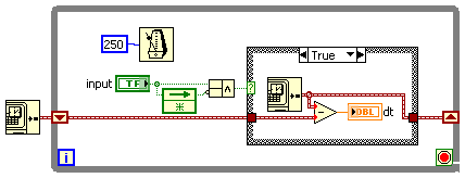
create 4 pulse digital output at the base of the ttl input signal
Hello
I am a beginner in Labview and would welcome advice on how to solve the following problem.
I'm setting up a train of pulses TTL and would like to send in Labview as input. Each falling edge detected on the input signal, I would like to as Labview to generate 4 pulse digital output. For each output pulse, I would like to be able to specify the period and duration. The image should illustrate more clearly, with the figures showing the expected scale.

System: NI PCI-6733 data acquisition card, Labview 8.5
My daq card has 2 timers 24-bit and 8 e / s digital, but I don't know what the best approach is to create between the pulse output of 4 to 8 of this precision... should it be handled at the hardware or software level? And how would I go about it
Thank you
-Sidney
Hi noli.
I found the problem, in fact PCI-6733 support only avoiding the digital output. The timing of software is limited to 1 kHz in case better.
I'm sorry, but this function is not possible with a PCI-6733.
Concerning
-
Question: CP9: can I turn off the message "do you want to display output?
Hello
The information dialog box that appears after the publication always asks "do you want displayed output.
I never want to look at the content and so click on the No button.
Is there a way to disable this message?
I looked in the General settings / Messages of Confirmation , but can not see an option to turn it off.
Thank you
Peter.
I don't know any way to remove this option. Do not hesitate to register a request for improvement with Adobe if you want, but I think that most people who publish would BE eager to see the results, so I doubt there will be many other similar applications.
-
generate the output waveform on 6259
Hello
I would like to generate signals of "simple" digital square output 3 6259 NI Board of Directors of 80 Hz.
Because of the wiring of my test tool driven 6259 Board, I can't use the output of the meter, but I need to plug into 3 output lines.
I re-used an existing vi and made by a subcontractor, but the generated waveform on my DUT does not have the expected frequencies (although it seems OK on the generated graph). Indeed, there are some forms of square waves, but not continuously. A sort of "pomade" and "elected" frequency does not match the measured frequency. If someone has an idea to help me, I have not experience on labview yet!
Thank you!
You have 4 unique digital States aimed at bike. Each cycle produces 1 full period of each of your square waves. If you want the output to 80 Hz, you must set the sample to run 4 * 80 = 320 Hz clock.
The other thing you see on the scope is that there are short bursts of pulses with parent long time between bursts. The calendar during the bursts are what control tasks. The time between bursts is caused by using the button "run continuously. Also that according to them, you complete vi almost immediately rather than waiting until they run awhile. Put an end to the execution of vi initiates self-cleaning of LabVIEW. These things represent the time brief burst and the ISH between bursts.
-Kevin P
-
Generate a pulse train, NI 9402 modules in cDAQ-9174 chassis
I have two modules NI 9402 in a cDAQ-9174 chassis.
When I output a pulse train on a specific line of the PFI to a specific module, the pulse train is out on the right line of PFI, but on BOTH modules.
I want that the pulse train out only one of the modules.
for example, I select cDAQ2Mod1/ctr1 to output a pulse train on PFI3 of module one. I hear the pulse module one PFI3 train, but I also get it on PFI3 of module 2.
I am also a measurement of separation of two edges with a different counter, but I don't seem to have this problem. (The measure only works when I have the signals connected to the module that I've specified.)
-Paul
This is the Vi I work with.

Hmmm... Looks like it's actually only after I exit a signal on that line. Maybe I should try to clear the line.
-Paul
-
I use the API C/C++ OR-DAQmx. How can I set up a counter to produce a single pulse redeclenchables? In other words, I need a pulse output, and then the pulse is generated, if a new trigger comes in, it gives the meter so that the timing of the pulse is extended.
What the DAQmxSetStartTrigRetriggerable property only? I guess the ability to do depends on the material used?
Thank you!
WM_John_Weeks wrote:
I need an output pulse, and then the pulse is generated, if a new trigger comes in, it gives the meter so that the timing of the pulse is extended.
...
The need is a replacement for the (old) OR-DAQ API GPCTR_Set_Aplication() with ND_RETRIG_PULSE_GNR with something equivalent in NOR-DAQmx.
I'm glad that you specified. ND_RETRIG_PULSE_GNR does not extend the time of the pulse if an additional trigger is received during the build. NOR-DAQ Function Reference Manual:
ND_RETRIG_PULSE_GNR:... Any door transition received during the generation of pulses is ignored.
With this in mind, the DAQmxSetStartTrigRetriggerable is actually what you want to use to get the same behavior in DAQmx.
Best regards
-
I would like to have a counter to a single output pulse whenever an incident occurs in a loop. My current solution (in pseudocode; I'm using LabWindows CVI on an RT target) looks like this:
DAQmxCreateTask (...);

DAQmxCreateCOPulseChanTime (...);

While (true)

{

  If (condition)

  {

    T1 = Timer();

    DAQmxStartTask (...);

    T2 = Timer();

    DAQmxErrChk (DAQmxWaitUntilTaskDone(*th,2));

    DAQmxErrChk (DAQmxStopTask(*th));

  }

}

DAQmxClearTask (...);
Unfortunately, the time between t1 and t2 is at least 0.142ms and sometimes 2ms is there an elegant way to reduce this and do not have to call the StartTask again and again?
Thank you
Jonas
You should get an improvement by committing to the task before your loop:
...

DAQmxCreateCOPulseChanTime (...);

DAQmxTaskControl (taskHandle, DAQmx_Val_Task_Commit);

While (true)

...
If this isn't good enough, you could try instead using a task of digital output (start the task before the loop, write twice inside the loop - high then low - whenever you need a pulse output). If the pulse width needs any kind of accuracy at all you want to use the digital output task to trigger an output meter (start the meter before the loop task and configure it to be "redeclenchables" so you don't have to restart several times in the software). I don't know whether or not it will actually run faster without benchmarking it.
Best regards
Maybe you are looking for
-
32L4363DG 32 "- subtitles are not visible in media player
Hi all I just bought this 32 "led TV 32L4363DG... .in using media player I can't do to display subtitles.I try to watch a mp4 file (i.e. yifi torrent) usb, but no subs don't make their appearance...I did it properly... the srt bears the same name as
-
Can DHCP server with two scopes - I have reservations in doubles in the two staves?
Hi all Not really a guru of DHCP, so be nice :) Currently, we run a DHCP service from one of our domain controllers (win 2008R2). The domain controller is the segment of a network (10.10.120.0/24), the computers making DHCP requests are on a separate
-
at the opening of windows live mail this notice appears every time
-
screen goes black after a few minutes inactivity
When I'm reading or watching something, the screen becomes black. If I'm streaming videos, audio is still on. If I hit the touch pad, the screen turns back on.
-
Typing Chinese on my emails using Windows 8
My IME pad doesn't seem to work on my email... accounts any recommendation to ratify it?