Wiring of the PXI-4132
Hi all
I would like to know how to wire the PXI-4132. You can check the links below specification.
http://sine.NI.com/NIPs/CDs/view/p/lang/fr/NID/207349
http://www.NI.com/PDF/manuals/375128a.PDF
-My problem here is that I do not understand is that a terminal guard. (check the p5 on pdf)
The output HI and LO match ups and downs (current or voltage) source, you need to source.
The sense HI and LO correspond to the upper and lower (current or voltage) measurement, you need to measure.
-How to the voltage source and to measure current?
Seems to occur at the same time. That means output HI sense HI are connected to the same point and feel Lo and LO as well.
-Is this someone obtain a wiring schematic of the PXI-4132?
Thank you for reading and discussion
Vincent
Hello
You can call screws of TestStand or use the DAQmx driver so I think that it should be possible to make this kind of measure using TestStand.
Kind regards
Tags: NI Hardware
Similar Questions
-
Extract and save all the channels of the PXI-5105 with 4 M of edge detection... Help!
Dear collegaues!
Please help me to improve my request, exhibit attached and sorry for my English.
So my task is to extract and save all the channels (eight) of the PXI-5105 with 4 M of detection of peaks and sample rate 4 M with loop 1 sec...
Entered all my channels are wiring detectors NaI with 0, 5... 1 microsec pulse (really) width and 0 kHz at not more than 40 kHz freq.
Why I chose the registration of 4 M and the sampling frequency of 4 M namely? Answer is that I tested previously PXI-5105 40 kHz generator and pulse width 0.5 microsec. It works great and detection of peaks indicate 40000 pulses/s for me. If I set lower than 4M record and sample rate of 4 M, it is without work. In my honest opinion record 4 M and the frequency of sampling of 4 M are parameters very min.
In the detection of peaks time present only 6 working channels... When I connected to diagram more 6 "detector.vi peak" - I see the error "...". out of memory... ».
Advise me please, what needs to be done to it, it's all working well.
-
Is it possible to route signals of relaxation between two chassis PXI-1002 with the PXI-8335?
Hello
as the subject says, I am interested in the delivery of a signal to trigger between two chassis PXI-1002. At present, these two chassis are connected by a MXI - 3 system using maps PXI-8335. The software is Labview 2010 sp1 and 380 NIScope drivers.
We want to keep (a PXI-5122 by chassis) scanners supply separated due to the requirements of our measure! The chassis are connected via cable to fiber optic. This explains why I can not just use the shutter release in Star, or connect via 'Trigger' or 'clk' cards (the inputs / outputs to the front of the cards).
I found a few examples, but they seem to all be designed for use with a chassis only, I'll call later to the examples that inspired me to this point. Each guide explaining the synchronization of several chassis systems seems to use another material or VI is not accesible to me. This makes me wonder if my hardware has the capacibilities I need.
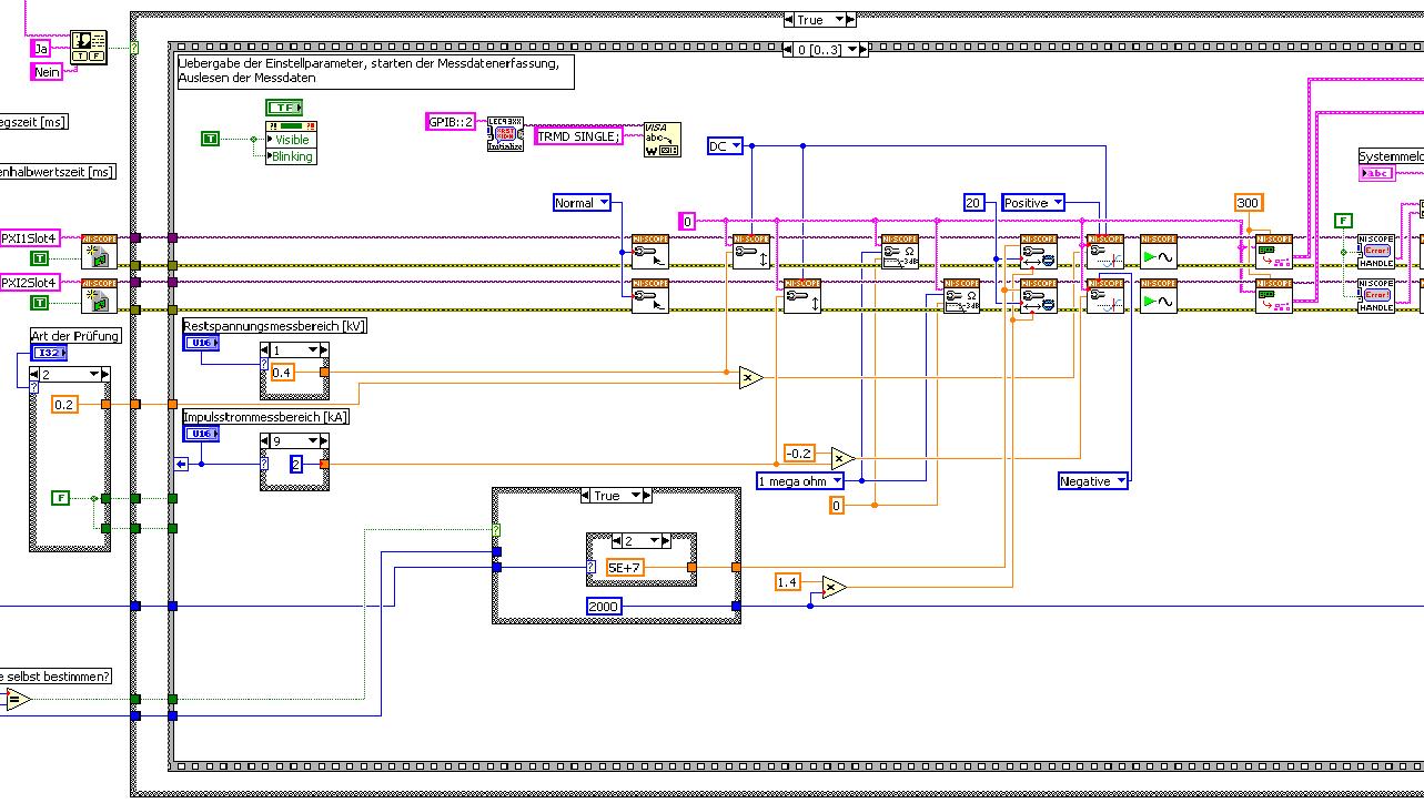
The first picture shows approximately where I started from (sorry I can't post VI, confidential...):
Only the middle part is interesting. Two sessions are initialized and manipulated parallel, trigger too. This has led to delays in the signals and should now be fixed. This apart from the VI works fine.
Goal is to trigger only on one channel but both devices! If possible, the device will trigger must be chooseable.
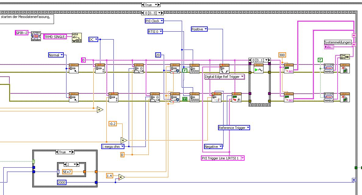
I started to rebuild the VI using the "EX Synchronization.vi 5xxx niScope' seeming spontaneity. The result is shown in the following image:
I tried different RTSI lines, but had no positive results. only the main channel has triggered.
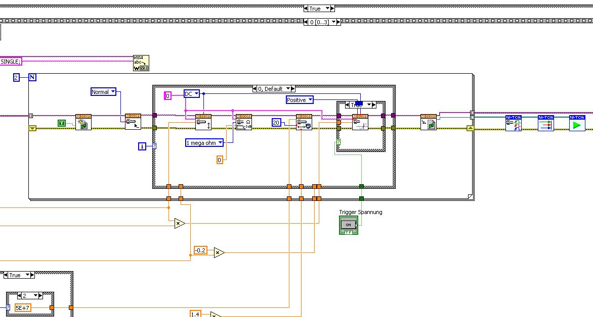
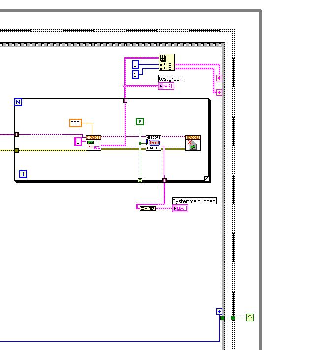
After this first approach, I looked in the "niScope EX .vi multi-Device configured Acquisition (TClk)" and other examples of TClk which seem to work for similar problems. The VI of reconstruction can be seen in the following images:
(Sorry, I had to use two photos..)
In this case, I didn't have no choice for trigger lines, it would automatically set the VI TClk. I tried to trigger on both devices, though. This second approach seemed promising to me, but it was an error:
"niTClk Synchronize.vi:1".
Index (starting at zero) of the session: 1
The error reported by the pilot of the instrument:
No registered trigger could be found between the
devices on the route.If you have a PXI chassis, the chassis correctly identify in
MAX and make sure that it has been configured correctly. If you use PCI
devices, make sure they are connected with a RTSI cable and that the cable RTSI
is saved to the MAX. Otherwise, make sure that there is an available trigger line
the trigger bus shared between devices.Source device: PXI1Slot4
Target unit: PXI2Slot4
Status code:-89125niTClk Synchronize.vi:1
Index (starting at zero) of the session: 1
The error reported by the pilot of the instrument:
No registered trigger could be found between the
devices on the route.If you have a PXI chassis, the chassis correctly identify in
MAX and make sure that it has been configured correctly. If you use PCI
devices, make sure they are connected with a RTSI cable and that the cable RTSI
is saved to the MAX. Otherwise, make sure that there is an available trigger line
the trigger bus shared between devices.Source device: PXI1Slot4
Target unit: PXI2Slot4
"Status code:-89125"
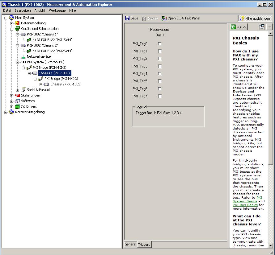
This error came back even after I've identified this drug as possible to the MAX, as shown in the screenshot:
In some of the textbooks, they showed how to get the MAX trigger lines, but as you can see, there is only booking options in my MAX. Whatever I do, I can't find options to define how to get my trigger signals...
In principle, it is possible to trigger instruments in different chassis, which is indicated in this Guide and others... the question that remains is can it be done with my set of components?
I understand that the use of multichassis compromised the integrity of the lines very adjusted as trigger in Star etc., so the configuration should be taken into account in some way, that my approach does not, I knew... But there must be a way to do this? And to start: to get just any signal from one device to the other trigger!
For any advice on this issue, I would be very thanfull!
Concerning
Max1744
Hi Max,.
Thanks for the detailed post and explanations of your application and requirements. You're right using TClk, because this is the optimal method to synchronize the 5122 digitizers. The original VI you worked with is unique for some of the legacy scanners and does not directly work with scanners based on the most recent CMS (for example the 5122). The good news is that you can synchronize these cards to separate chassis, but it will use the calendar 66xx and synchronization (T & S) cards in the chassis of the master and the slave, as indicated in the guide that you have accessed. These are needed because a common reference clock must be shared between them as well as a couple of tripping. MXI itself can not handle export triggers and clocks, so there is no way to do this without physically wiring between the chassis with cards T & S. Unfortunately, regardless of what specific method, you use for synchronization, it will take a material extra beyond what you currently have.
As one of your needs looks like it is necessary to retain wiring between the chassis directly, you may need to consider to synchronize using 1588 or GPS protocols. 1588 Protocol is a system for synchronization on the network while GPS course use antennas and locks for a common wireless signal. Although these synchronization methods may allow you to keep your chassis isolated, they will also require some manual configuration because you would be able to use the TClk synchronization and so the level of synchronization you can get between the cards may not be as good that can physically wire signals between the chassis using T & S cards.
Hope this helps,
-
Programming on Board on the PXI-6132
Hello
This is my first post, so please be abstain.
Asked me to develop a Labview Vi for the acquisition of data. I must acquire and a number of disintegrations exponential (as happens during the discharge of a capacitor through a resistor) averaged for calculating the decay constant. My boss has already bought a chassis PXI-1073 with a PXI-6132 to acquire the data. My question is this: since the sampling rate must use is very high, I want to minimize the amount of data transferred from the PXi system to the computer, with my system (windows 7, LV 2011, nor-DAQmx?), so it is possible to "say" the PXI-6132 to isolate the data belonging to the decomposition of exponantial on average several decays, then send the data to the host?
Thanks in advance for your help
Channel counter in the example I did you, is the meter, you use to generate the clock signal. Therefore a finished with 30 pulse pulse train if you want to acquire 30 samples.
This channel can be configured as redeclenchables and control 'Source', you must select the PFI where the trigger signal is wired. It depends on how you did.
The clock signal is routed internally, which means that you don't need all cabeling, simply select the right source for your route of entry of the AI (for example. Ctr0InternalOutput if you selected against 0).
So external signals will only be ounces you want to measure with Amnesty International and the trigger for the clockgeneration (counter) signal.
In MAX, you can do a right click on the device and see the layout of the pins on your device.
-
After the initial setup time machine should be hard wired to the modem
Should time machine be hard wired to the modem after initial installation
Yes, if it must be used in its default configuration as a router DHCP network and all clients need to connect to the World Wide Web.
-
OR DC Soft Front Panel, minorbug, small bug with the PXI-4110
Hello
The NI DC Soft Front Panel V14.0, with the PXI-4110, scrolling to negative tension, works as expected to-10V, but then returns to 0. If we change from - 1V procedure, it goes...-8-9,-10, -1, -2... instead of-8-9,-10, -11, -12...
Everything about her, a simple thing that I miss is a switch for all three voltages.
(Also, IMO, it would be logical for negative tensions with the arrow pointing down, not more).
My 2 c
Hello Janaf,
I completely agree with two of your statements, I tabled a report of corrective measures that you can monitor in the next versions of DCPower to see if this is fixed with the FPS. CAR number: 512257
I've added notes that only manual insertion of numbers - less than 10 works and that it was not logical to use arrow increment or upward arrow to reduce the output voltage.
-
What pins to use to receive the data from the PDS ELITE RS485 with the PXI-8431/2?
Hello!
I use the PXI-8431/2 to read data from the flow meter PDS ELITE (Modbus RTU). Receiving data, the RS485 protocol request to terminals 4 and 5, but this configuration does not seem to work. When I connect the RS-485 converter USB of Microflex I get the data correctly, so somehow between the PIN lay and PXI this problem there.
Can someone help me?
See you soon,.
Steven
Hello Steven,
I think that what was Hossein trying to send you is the following:
How to connect and configure a device with RS-485 2-wire
Can you also tell me a little more what you use to read the data? What environment. You have 2-wire or 4-wire Modbus RTU?
Kind regards
-
Variation of thermal EMF of the PXI-2530 modules
This message/question is a companion of my the most recent message in another thread.
In addition to watching some resistance higher than expected that affected current measurements using modules PXI-2530 multiplexer 4W topology, I saw systematic variation in track-to-track blood pressure measurements. Tensions would increase gradually through the 16 channels in a configuration by measuring the voltage at the terminals a resistor 1.5 kOhm with 0.5 au crossing (75 uV). I've identified that the thermal EMF of the reed in the PXI2530 module switches is on the same order of magnitude of these measures and set out to quantify the differences EMF thermal track-to-track between my three modules.
Test method: I have a TB-50 which is configured to mux the signals of tension for a DMM. I connected each of the four DB-50 one cable of 176 pins to this block and collected with a PXI-4071 pressure readings set to 7.5 digits precision in the range of 100 mV and > 10 GOhm impedance. For most channels, it took several minutes for the voltage stabilize - or at least appear that it was to stabilize.
I enclose three graphs. Note that the vertical scale is the same on each.
Data that triggered this survey was collected with MUX1, via connector P2 to voltage. The magnitude was not quite the same-probably related to the phenomenon of stabilization time, but obviously the worst group of channels three multiplexer modules.
The three modules were all bought at the same time (about 2 years ago), but had only limited its use in the first year or more. The three now have various 'mileage' based on my use. But MUX1 clearly behaves differently two other modules. The
I changed my test conditions to spend 0.5 au via a higher resistance to thermal EMF less important. The PXI-2530 sheets indicate that thermal EMF must be less than 50 uV. In most of my measurements, it is. But not for MUX1!
Any thoughts?
Thank you
Jeff
Hi Jeff,
You can check that all the three modules are PXI-2530, not PXI-2530 b (while, as the PXI-2530 b parts slightly higher thermal emf)?
Specification of emf thermal 50uV of the PXI-2530 is a typical value, is not a guarantee of spec. See a few channels higher than the spec is not a cause for alarm, but it shows that we must take account of this in our measurement error. Note that the industry standard for the technical measure thermal emf is to close the relay, wait a few minutes and then take a measure of tension. For example, if you scan through a switch faster than a relay per minute or so, the thermal emf will be less predictable and stable. A single module performs worse at these low voltages is not indicative that this module is a failure, etc. the module is fine. Unfortunately, the reed relays have more emf thermal relay of the armature, mainly because of the many layers of metal in a Reed compared to a frame (each metal junction is a source of emf if these metals are not the same).
Thermal EMF is proportional to the temperature, it may be interesting to note the position of the chassis of the less powerful module. Placing hottest modules (scanners, Ara, RF, etc.) will reduce the thermal emf.
-
Use the PXI-2630 terminal block in a matrix configuration?
My apologies in advance for the length of this post!

I use the PXI system with PXI-2530 switch modules, related to a series of USE with PXI-2632 (1W matrix 8 X 16) connector blocks and a PXI-4071 DMM for each switch module. My request, uses the PXI system for measurement of current and voltage external to verify and/or benefit from restraints of reliability. A requirement of the application, therefore, is that there must be a ride from DC through each USE with change of the minimum impedance as the application between its "bypass" mode switches and its mode 'measure '.
I used this Setup with connector blocks of matrix in conjunction with one of our test systems, and I am satisfied with the results. I started working with the Test System, has no easy connection to catch HAD, I needed to build a kind of interface the PXI system and a resistive faced load HAD, it was not difficult to build in the wires that attach to the Terminal screw of the 2632. He did turn into a nest of a coded son rat I did my best to keep clean and tidy in different bundles, however. Fortunately for the cable fasteners!
My next task is to use this application with system B Test, which has an interface of pines buck header with which each signal that goes to or from the DUT can be obtained. No welding or pass the wires through the openings where the designers have no intention of son to be stuffed. I intend to build a break-out Board that allows simple connections between the modules PXI and the number of Test B system which we have or will have in our laboratory. In order to simplify the configuration/installation, I want to reduce the number of connections to terminal block screw. Preferably, I would like to completely remove the screw terminals and use lever-based connections where I can't have mating of the headers. The PXI-2632 terminal blocks unfortunately use Terminal screw.
In matrix mode 8 X 16, the closing of the PXI-2530 switch kcom1, 3, 5, 7, no matter what points in the array are connected. A link between the row of right and column C is done by closing the switch corresponding to k (16R-C). I checked using the Soft Front Panel.
I also have a number of connector PXI-2630 blocks. These are intended to be used with the switch module in one of its MUX modes and include 8 banks of connections of the header 2 X 9 pins. In the the 2530 documentation and 2630, I identified that switch k-x is associated to chX output pin, ch0-15 related to the pins 1-16 from Bank 0, C16 - 31-associated pins 1-16 of Bank 1, etc.. X = 16 B + P-1. PIN 18 of each bank is used for independent MUX topology comX. Pines multiplexes sixteen seem to correspond to the sixteen columns of the matrix, with eight common lines corresponding to eight lines.
Here's what I would do, but I would like to ping the forum to see if anyone tried something similar and wisdon to share the thought:
- Make custom cables which connect the pins 1-16 of all eight banks 2630's header with a single Ribbon connections 16 son carrying the signals emitted by the interconnected banks (poles!).
- The custom cable bundle will also include a wire connected to the pin18 of each of the eight banks (line connections!)
- 24 total wires in the harness will end in the header connections who will probably partner by the lines that I currently connect to each object to be measured.
- Make additional harnesses that interface with the Test System B header pins.
- Make a map of derivation using band Council or a similar material to provide header pins to connect the two above custom cables and allow the connection of other elements such as resistors using Terminal level.
I checked this concept using the Assembly of 176 pins four terminals, like a bunch of little pieces of wire and cable. Are there other issues that I have to configure, such as the elements of a terminal that establish physical components of the switching topologies? The bowels of the PXI-2632 provide more features than the interconnection of the sets of eight sixteen pins? The bowels of the PXI-2630 connect elements that do not allow my proposed scheme?
I appreciate the suggestions and all entries!
Thank you
Jeff Zola
Hi Jeff,
First a correction to my previous post: 2632 Terminal has no reed relay protection resistors as I said earlier. The resistance that you were referring to the 2632 and those that I confused, is there to connect the columns of the switch. Resistances have a resistance value zero and act as the electrical connections. The 2632 connects columns c0 to c16, c17 c1, c2 to c18 and so on. Switch cards 2531 and 2532 have the protection relay reed on board resistors.
As for resistance in the map that protect the reed relays, they are generally very low and do not significatly affect even small tensions that pass through the switch. The resistance won't affect all currents in the map. Any effect that the resistors have on tensions will be with the precision of the switch card specifications.
Thus, to address the other issue in your post, there is no resistance in the connectors because they are not necessary.
-
Control of low level of the PXI-2596
How to control a PXI-2506 Mux 26.5 GHz Dual 6 x 1 chassis PXI-1042 a code 'C' with a minimum of drivers? We want to use our own code, not of LabView, just plain 'C '. Also, we prefer to use our own controller (Linix based) shipped without a slot for a PXI card (if possible). Is there like a simple series or ethernet interface to control the boards housed in the PXI-1042 chassis? The switching speed is very low, it is part of a manufacturing test system, we want to use the PXI-1042 with several 6 x 1 Mux inside for instruments RF switching in of the DUT.
Hi eirlund,
In response to your questions:
Is there a simple series or ethernet interface to control the boards housed in the PXI-1042 chassis?
- Chassis PXI itself contains only the connections for the PXI bus and some timing and triggering and power for the cards. This white paper explains the PXI architecture in many more details: http://www.ni.com/white-paper/52018/en/
- In order to be interfaced with the cards that you need to use a controller Embedded PXI or a remote control which allows you to use another computer in place and place an on-board controller. A remote control can be easier to apply to what you're after however there are some limitations regarding the use under Linux. More information on what the remote controllers can be found here: http://sine.ni.com/nips/cds/view/p/lang/en/nid/10359
We want to use our own code, not of LabView, just plain 'C '.
- You should always use the relevant drivers for the hardware you are using, in this case NOR-Switch and NI PXI Platform Services if you are using a remote control.
- These drivers work with LabWindows/CVI which adds additional tools to facilitate the programming intended for the material OR in C, this means that it should be possible to use these drivers of C, but there is less evidence for this
Also, we prefer to use our own controller shipped (Linux-based) without a slot for a PXI card (if possible)
- If this is possible will depend in part on the question of whether the version of Linux you are using is supported. You can look into this further here: http://www.ni.com/product-documentation/52786/en/
- In addition, you will need a PCI slot or a slot ExpressCard to connect to a remote installation program with
I hope that this information gives you somewhere to start to consider whether what you want to do is doable?
Best regards
Joe
-
The specifications for the PXI-4071 DMM indicate the input resistance can be chosen as 10 MOhm, 10 GOhm of the 100 mV 1 V and 10 V ranges. I see where it can be entered on the soft dashboard, but I could not find how to set up the input resistance when you use the DMM in a VI. Suggestions?
Thank you!
The f
You must use a property node.

-
Acquire more than 2047 samples with the PXI-4461 instaled in SMU-1073
Hi all, I would ask you for help with the buffer limit.
I intend to buy digitizer PXI-4461 and he instal in SMU-1073 chassis, namely control via MXI Express of Labview installed on a separate computer.
What I need:
-to acquire data of a single channel of AI, but at least a sequence of 20 kS by a acquire task, in some situations until 200kS by a task to acquire.
The question:
- I can gain more than 2047 samples in a single sequence, like 200kS, with the PXI-4461 installed in SMU-1073?
Internal buffer of the PXI-4461 is reserved to 2047 samples. So I'm not sure if Labview can download remotely via MXI Express the data in the buffer of the PXI-4461 via MXI Express fast enough without any affection of the sampling program.
-in the case, this PXI-4461 with SMU-1073 isn't the right combination, what chassis and a controller can do?
Thanks much for the reply
Jan
It will work for you.
The on-board buffer 2047-sample is used only as a backup if the flow of data to the PC host (via MXI Express in this case) is not fast enough... that it will be (explained below). DAQmx transfers data from the buffer of the device to the host PC as fast as he can and, in ideal conditions, should not save the buffer 2047 much at all.
Let's just say you get 110 MB/s (randomly from a MXI data sheet) flow on your MXI connection. The 4461 has 2 analog inputs, which will be at 24 bits, we just round 32-bit in case it transfers the data in this way.
4 bytes/sample (32 bit) x 200,000 s/s x 2 (channels) = 1.6 MB/s, which is well below the 110 MB/s, which will make the MXI link.
clear as mud?
Germano-
-
Usability is NOR-SCOPE Soft Front Panel for the PXI-5154?
I am plans to use the PXI-5154 with his NO-SCOPE Soft Front Panel in a product to test instrumentation. Our past experience, our users need an on-board scope that is easy to use which does not load the CPU. In most cases the scope will be used to check a transitional type of pulses. So, the amplitudes and rise times are essential to ensure compliance with ISO standards. The ability to capture, store and recall traces of reports is important, as well as the ability to perform simple and reproducible follow-up measures. We don't expect our users to have to program the scope; "give me the waveform.
Does anyone have any comments on the usability of the NOR-SCOPE Soft Front Panel? How to compare with other soft scopes?
Hello!
The scope Soft Front Panel is very user friendly and able to load/save waveforms, Load/Save settings and make the scalar measures. I've attached a screenshot of what the front soft worn looks as well as a link to a help document on the high speed digitizer HELP. Information on the scope Soft Front Panel lies in this document and can be found under the tab content in the configuration tree (NI - Scope Soft Front Panel help).
Help of digitizer OR high speed
http://digital.NI.com/manuals.nsf/WebSearch/2123F564C6DE7B27862574DE006915DE
-
Remote control of the instsrument of the PXI controller
Can you suggest the best method to control PXI instruments with an external controller? I have two machines. A standard desktop system and a PXI chassis with controller and installed instruments. I can the remote desktop for the PXI chassis. I expecting MAX to recognize instruments in my desktop computer PXI chassis and use VISA address as if it were local. If possible give examples for a starting point.
Thank you!
The Keysight support team helped me to solve this problem. They showed me MAX remote system control and walked me through the Setup program. The link they sent me from the site NEITHER.
http://digital.NI.com/public.nsf/allkb/F3AB0B5D7DBA367C86257982005BBF2C
Thanks Keysight!
-
Pulse modulated CW with the PXI-5650 and PXI-6653
Hello
I'm trying to generate a signal CW of pulse modulated with the PXI-5650 as source RF and the PXI-6653 as the modulation signal. Basically, I'm trying to generate a simple radar waveform. It seems that it would be possible to use the synchronization Module (6653) to transform the RF output on / off on the signal generator (5650), but I do not know how to route the signals from one to another using LabView.
Has anyone tried this or something like this before? Can anyone please offer some advice?
Thank you!
-John
Hi John,.
Reading your post, it seems you want to use your calendar and map of synchronization to the RF output power, in other words, on Off Keying. OOK modulation is a feature built into the 5650. For more information, you can navigate through the NI RF Signal generators Help for devices-RF signal generators > NOR -> NOR 5650/5651/5652 overview-> Modes of Modulation and simply click on the Modulation Modes.
An example of this is found in the example Finder OR by navigating to the help-> find the examples in LabVIEW and then navigate in the Finder to example NOR material input and output-> Modular Instruments-> NI - RFSG-> signals-> RFSG 565 x Digital Modulation.vi.
Kind regards
Jason L.
Maybe you are looking for
-
Some messages in unwanted file in iCloud.
Some of our spam goes in iCloud, how do fix us this?
-
Not able to install KB2345886 gets error failure to configure updates.
Original title: failure to update given. When I start my computer, I have a problem in windows. failure to update windows 7 x 64 kb2345886
-
psc2510 work before the power failure, crashes attempt to restart only show a static hourglass
failure fine t. prior printer doesn't work. Once the power is re-established, printer will not end the initialization process, everything crashes and a static hourglass appears, running windows XP Professional, HP printer to wireless photosmart psc25
-
Trying to fix a 530 s that does not start
There was a power failure in the in the neighborhood. The green power light is on and there is an orange light on the motherboard. the button "power on" does nothing and does not illuminate. I disconnected the cable 24-pin motherboard and jumped with
-
RequestBackground startup failed
Hi, I have the following project with "Auto run at startup" checked, tested in OS 4.5 Simulator. This project starts automatically with GUI screen. Even if I ask him to go back just after pushScreen, but the GUI screen always shown without going insi